

With the Mazda platform, the most common scan equipment on the market would be the IDS, Snap-On, MAC, Autel, Launch, etc.
Most, if not all, can read the entire network(s) of the installed controllers and also include bi-directional control(s).
What about ELM327 devices – DIY
Years ago, these devices (or versions of them) came into the market as simplistic OBD II code readers that connected to a PC three different ways:
- USB
- Bluetooth
- Wi-Fi
All three personal versions are in use and we have been working with them over many years but prefer the Bluetooth version. Bluetooth is far simpler.
Most Android and Apple devices connect in the same fashion—USB needing adapters and software if required.
| Tools Used |
|---|
| FORScan |
| CarDAQ Plus attached to Wi-Fi |
| OBD extension cable |
| OBD extension cable |
| 90 amp floating power supply |
| Manometer with test cap |
| Camera, pen, paper and screen-capturing software |
OBD II has been talked about to death but there are some new, interesting applications that are eye opening. Keeping it simple but understanding the modes OBD II offers, is a reliable and simplistic diagnostic approach.
Let’s change the rules and dive into FORScan
This application comes in two flavors. One for the PC (this one is on steroids) and another for the smart phone or tablet version.
The PC version has the most options with bi-directional control.
There are multiple flavors of ELM327 devices that “just about everyone under the sun sells.†Many are not very effective. There are however, very good OBD II applications working with Android or a PC.
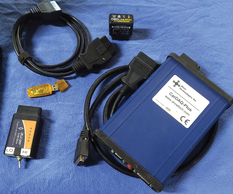
Personal preferences that work
- ELM327 v1.4b (BAFX versions are flawless)
- OBDLink MX+ (STN1100 family with firmware updates)
- J2534-2 CarDAQ Plus (WiFi) and Plus2 (USB)
Added is a 1 meter OBD extension cable (never lose that OBD tool again).
This application (FORScan) works on Ford and Mazda models. Honorably mentioned are the Jag models that wanted to be a Ford. If the Jag model used a Ford network, you may have a scan tool with the ELM327.
Depending on the preference and what type of interface is being used, all have distinct benefits:
- (A) The ELM327 v1.4 or v1.5 is the most stable. The “purchase†will need an internal update. It’s small and portable. Those details will be in this article.
- (B) The OBDLink MX+ needs occasional updates and is just as portable.
- (C) The J2534-2 devices work as well and are very fast compared to the ELM devices. They are not the “pocket size†but work well inside and outside the service bay.
What is the update?
The general purpose, well designed ELM327 device has communication lines that meet anything that is OBD II model compliant.
Ford and Mazda models use two networks: High Speed CAN and Medium Speed CAN.
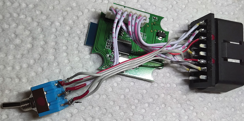
The simple update is a switch (Double Pole, Double Throw [DPDT]) that is easily installed into the ELM327. FORScan requests a connection if the switch is installed that will access the networks and the attached controllers.
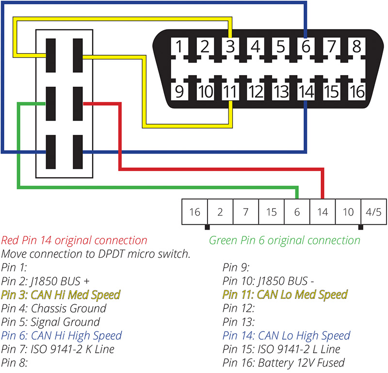
A non switching ELM device would have the illustrated green and red wires connected to the High Speed CAN High and CAN Low connections at Pins 6 and 14 on the DLC. This will be the standard connection for the ELM328 device.
Using the diagram, Pins 6 and 14 are removed from the DLC and connected to the DPDT center terminals.
The updated ELM and DPDT switch will connect Pins 3 and 11 (Medium Speed CAN) or Pins 6 and 14 (High Speed CAN).
| NOTE |
| Not all ELM 327 pin layouts on the circuit board are identical; use the hand made Photoshop illustration and notes. |
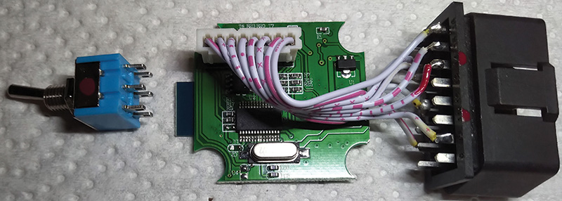
With care, razor off the label and place it aside, remove the four screws and open the shell.
With the device opened and laying the DPDT switch in line with the ELM, some paint marks in red identified pin 14 and the blank pin 11 of the DLC. The switch was also identified with a red dot.
An old computer ribbon was used to make up a harness and attach the extra CAN wires from the DPDT switch to the DLC.
The paint mark on the pin 14 original wire of the DLC is to be de-soldered and will be soldered to the red side of the switch (center contact leg).
The opposite pin 6 of the DLC will also be de-soldered and soldered to the opposite side of the center contact leg of the DPDT switch.
| Note 1 |
| Toggle the switch and the layout of the pins is evident with the shop multimeter. |
| Note 2 |
| The added 1 meter DLC extension cable brings the ELM or OBDLink to the operator for control or left on the dash. Reaching under the dash and fumbling with a switch becomes a… distraction. |
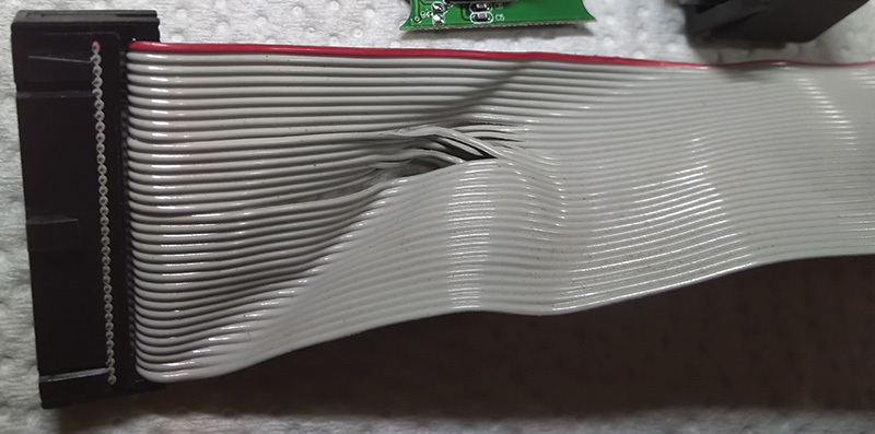
Four wires of the ribbon cable must be manipulated. At the red side, mark the CAN High pin 14 and solder it next to one leg at the end of the switch. With that wire, solder it to DLC pin 14. On the opposite side of the switch, solder one wire to the switch for pin 6 and that opposite end to pin 6 of the DLC.
Circuit board Pins 6 and 14 are now reconnected to the middle portion of the DPDT switch with Pins 6 and 14 of the DLC.
Pin 11 of the DLC has a sacrificed wire soldered to it. Paint it red. The opposite end is soldered to the opposite end of the switch on the red side.
Pin 3 has the last wire soldered to the DLC and its opposite end is soldered to the remaining pin of the DPDT switch.
A switched network is now created.
Simply, the painted marks are a reference and directly fit the diagram.
A few have been made for close associates, friends and acquaintances. With a high degree of care, all have survived to this day.
Some, but not all ELM devices, will fit the switch on the end and, in some cases; the switch is mounted on the side. In either case, the cover of the ELM should be identified as HI and LO relative to the switch position.
The HI position is the standard position when diagnosing in OBD II mode.
The FORScan software can be downloaded here: forscan.org/download.html
It’s free to use all day long.
Pick the flavor and again, the PC version has much more to it.
Read about the license and choose the immediate needs.
Sign up at the FORScan web site to access a license.
Without a license, no adaptations or bi-directional controls are available.
What about the 2011 Mazda 3?
It just so happened, the facility had a slight struggle with this model and got dragged into the “mystery.†Their first order of business was to solve a MAF and misfire set of faults. The MAF fault constantly returned and the engine tended to struggle up to idle speed and seemed like a long crank condition. Unfortunately, the primary faults were never saved.
The setup: In this case, the J2534-2 was used.
Since this version is licensed, the setup is by no means difficult for the ELM327 or OBDLink MX+. Use the pairing code that came with the device.
Codes can be: 1234 or 6789. Read the documentation with the device(s).
The J2534-2 can be a direct USB connection or in this case, a WiFi (ad hoc) connection to the laptop. If any or all devices have been paired or set up previously, they will automatically connect.
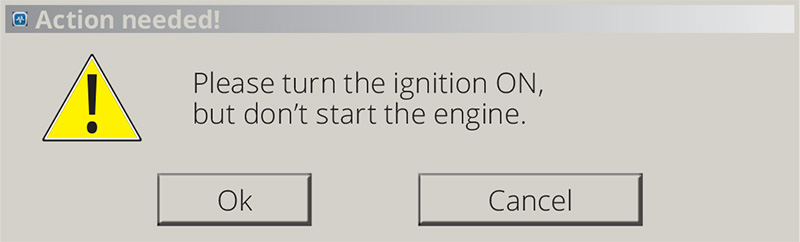
Remember to set the DPDT switch to HI first.
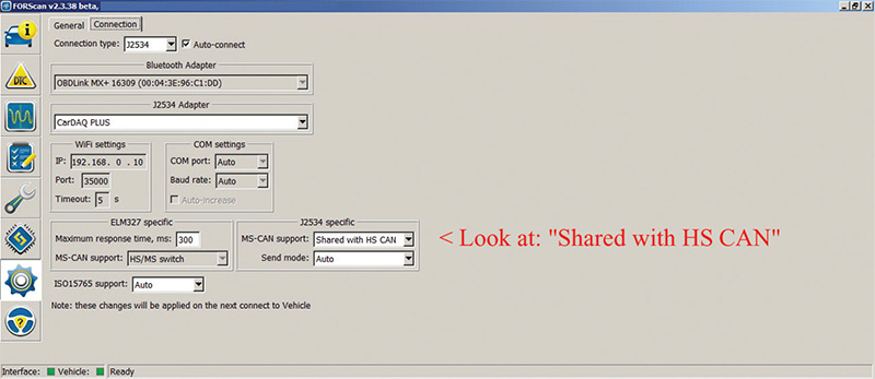
If using a J2534-2 device, there is one task to complete.
That one option has to be set the first time. J2534-2 devices will communicate with High Speed and Medium Speed CAN networks because MS CAN support is shared with HS CAN.
A J2534-1 device can not access the Medium Speed Network.
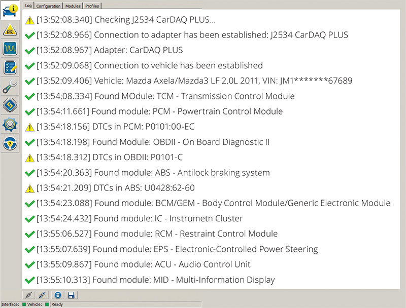
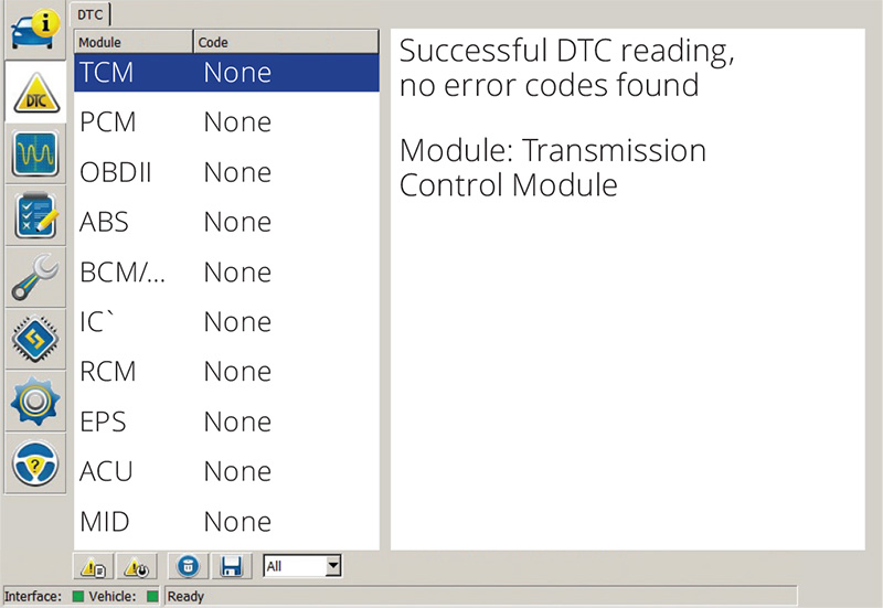
FORScan will connect to both networks and access the name of the controller(s) with the faults associated to that controller.
The switched ELM device and the software will request the required switch position warnings on the screen.
The top line (Figure 7) indicates the device that accessed the Mazda with the recognized VIN and software version.
The top tabs access: Log – Configuration – Modules – Profiles
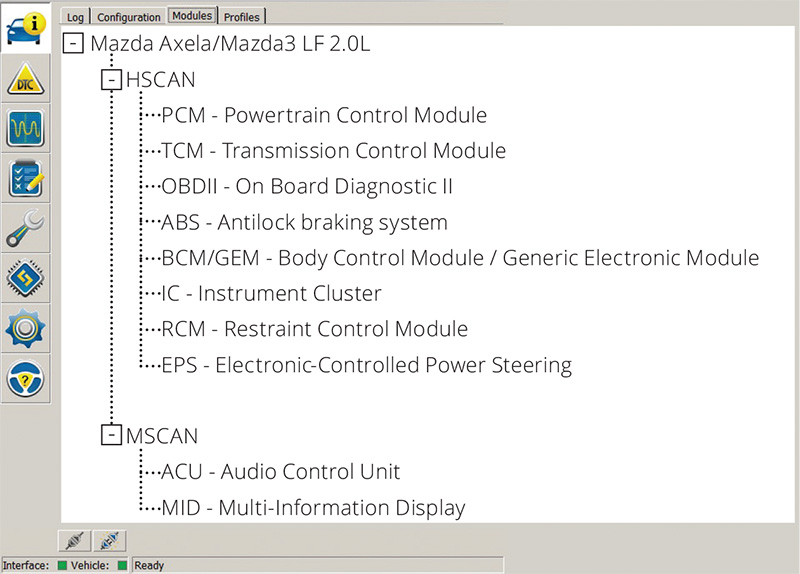
The Module’s tab indicates both networks the J2534-2 device has access to. The ELM327 device will “ask and confirm†the network switch; follow the guide on the screen and activate the switch in the correct position.
FORScan logs can be saved and found in “My Documents\FORScan.â€
The software displays a well organized view of all faults by clicking them individually. Saving the logs and numbering them will help towards a path and final solution when those faults are corrected.
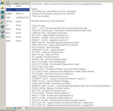
Clicking the OBD II at the left gives up the generic fault:
- Code: P0101 – Mass or Volume Air Flow Sensor A Circuit Range/Performance
- Status – Confirmed – malfunction is confirmed
- Module: On Board Diagnostic II
One more attention to add.
The vehicle owner or someone decided to also replace the battery. Unfortunately it was the incorrect size (dimensions) and the posts were at the opposite side. It did fit but we made sure the customer was aware of that purchase and possible update.
The battery became the reason for the next fault.
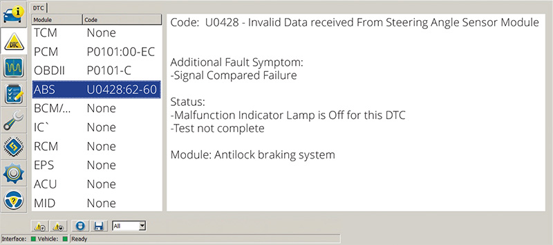
U0428 – Invalid Data Received From Steering Angle Sensor Module
Most notably – Test not complete
The suspicion was either a dead battery or jump starting it. Disconnecting the battery may have also lost the ABS Steering Angle Sensor calibration.
The day before, the facility replaced spark plugs and ordered a MAF sensor for the following day. The repeating fault may have been the reasoning for the shop to order a MAF sensor. Let’s see what live data
the PCM displays.
Access the PCM
To access live data for any controller, use the icon that resembles a sine wave. The next window will open the next choice to click the PCM.
Another window follows with all the PIDs the scan tool has access to.
The best and quickest method is to scroll the page, use the Ctrl and Enter key combinations to choose (highlight) the set of PIDs. Once the selections are made, click or touch the right arrow to send the selection to the right screen.
Using the up or down arrows can arrange the data in any order.
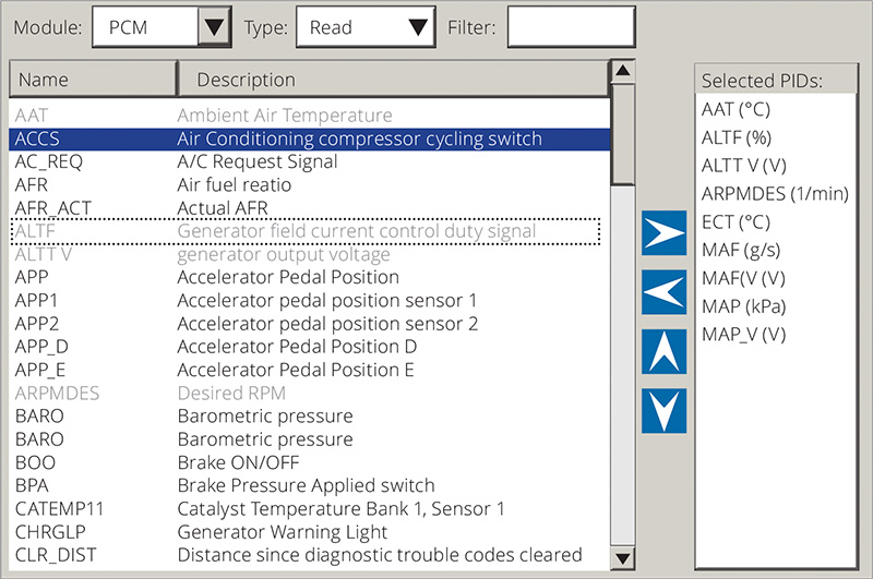
If the choices are correct and needed PIDs set is a live test, click the check mark at the bottom of the window.
The image “Data Screen†(next page) has a Play icon. Click it and the screen will populate with the PID choices.
Be aware with any scan tool. All selected PIDs are subjected to:
- (a) Request
- (b) Read
- (c) Write
- (d) Display
All this takes place one PID at a time, dependent on PC and scan tool processing speed.
And the process begins again at the first PID.
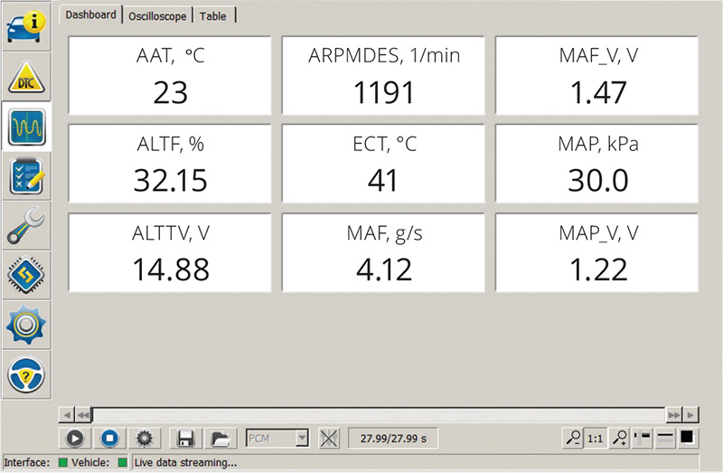
The top of the screen has three tabs. The image named “Data Screen†(next page) is associated with the Dashboard Tab. This screen indicates a cold start.
The image “Oscilloscope†(next page) begins to look more like other related software.
The next tab is Table. This is likely going to appear quicker in refresh rate and similar to the primary Dashboard. The MAF values appeared normal.
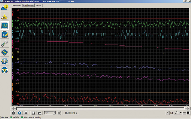
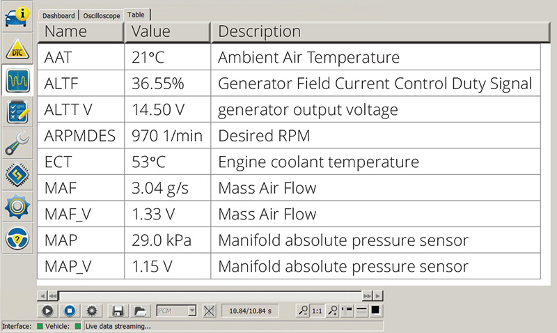
The Dashboard, Oscilloscope and Table tabs do work quickly together but great to monitor, especially with Screen Recording software for playback.
Starting the engine was interesting – Long crank – Repeating MAF Fault.
With the Dashboard or Table view, the data for the MAF looked reasonable but two more tests were attempted, just to make sure.
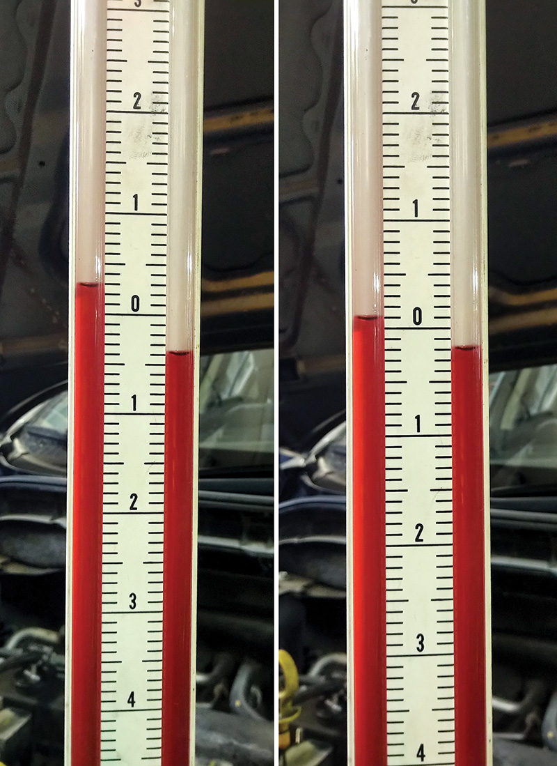
Test 1
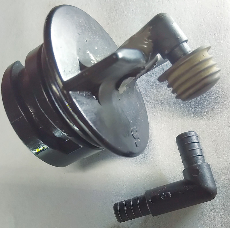
Two images side by side: The left image has the dipstick inserted in place and the right image has the dipstick removed. This is a valid test with no apparent PCV leaks. This test cap is a DIY from an aftermarket store and a battery vent tube glued into place. Consider this test as normal.
Instructions: Attach one end only from the test cap to the manometer. The other end of the manometer is open to atmosphere. Cap the tool when finished with the test.
Test 2
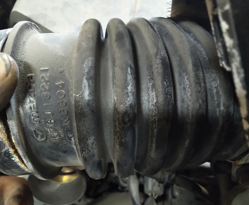
Disconnecting and stretching the air tube connecting to the throttle body reveals no tears and contains a new air filter. (See Figure 17, next page.)
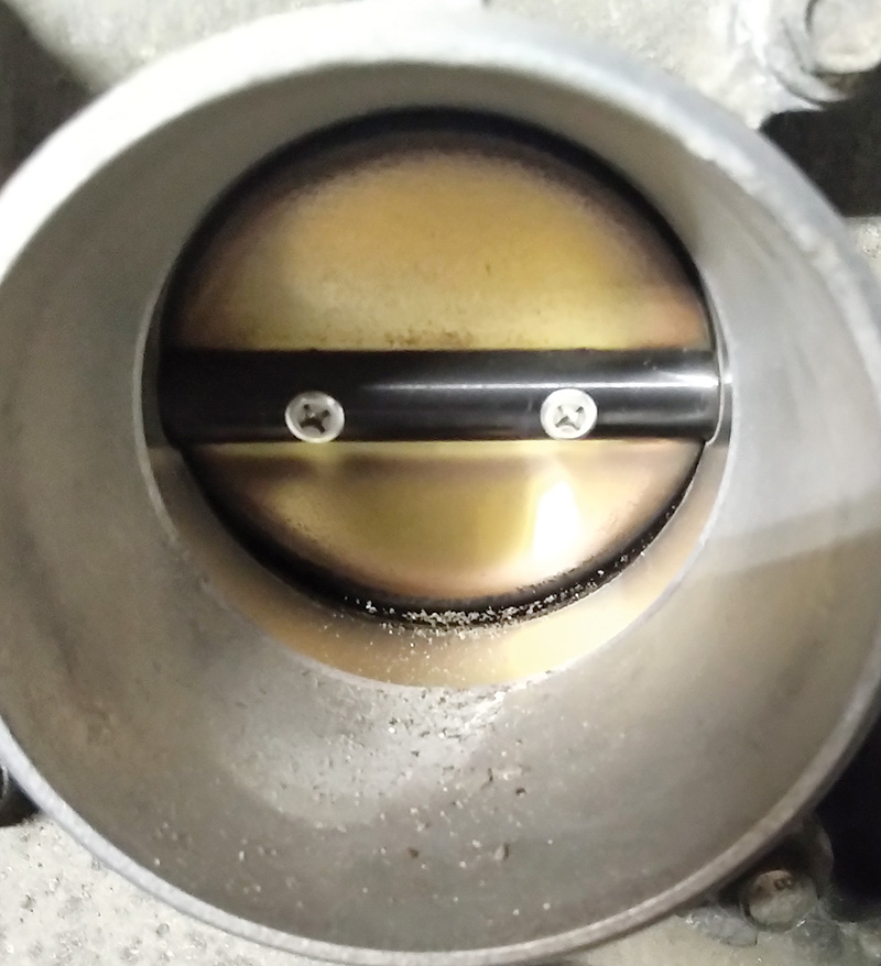
A deeper inspection revealed the reason for the long crank and MAF repeating faults. The throttle body was sticking from all the oil and debris stuck to the back side of the throttle blade. With a light, there appears to be more oil than normal puddling within the bottom floor of the intake manifold. This Mazda was due for an oil change within a month.
Did the shop installing the MAF sensor address the starting problem? NO!
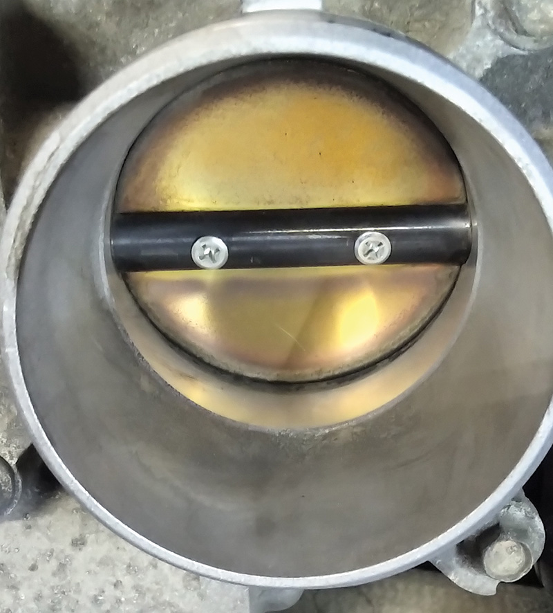
What the cleaning did accomplish was the immediate starting rpm increase and much faster startup. The starting rpm increase and drop to normal rpm was noticeable with the MAF fault not returning.
If the fault was evident, the MAF fault would have been recorded immediately without cleaning the throttle body.
The PCM had an expectation of a MAF value during cranking and startup. A contaminated throttle body decreased airflow during the cranking and eventual startup. A thorough brush and chemical cleaning was the solution.
What about the ABS fault with the Steering Angle Sensor?
The Steering Angle Sensor fault returned with every key cycle.
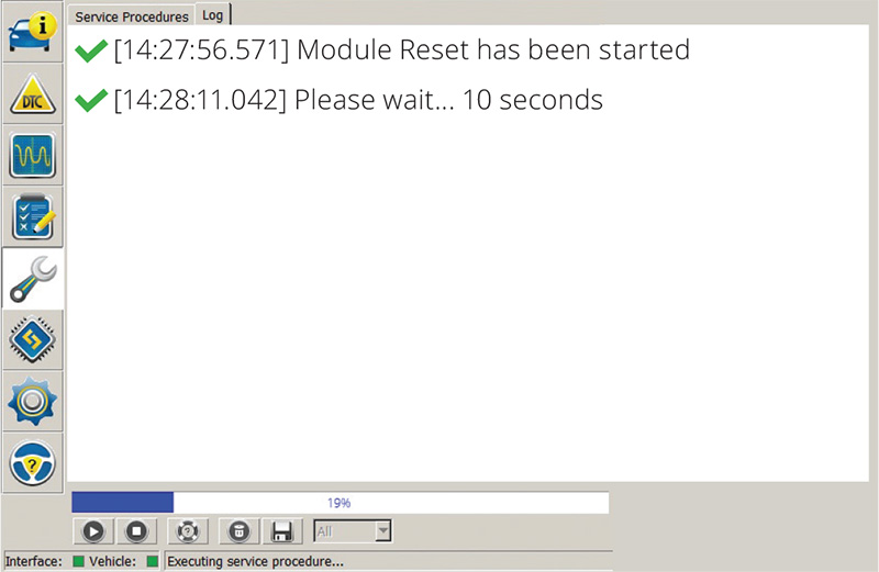
This is where FORScan accomplished and immediately reset the fault.
With a power supply attached, click the Wrench icon and choose the ABS control module. Click on the module reset option and wait until the time has expired. Heed all of the software warnings with any reset.
When looking at the layout and functions of this software, it is a reminder of other scan tool functions available on the market.
With this model, the inclination was to leave the driver’s window open and reach into the passenger compartment to cycle the ignition key. During this test, there was no intervention, no one sat in the vehicle, the steering was not moved (dead ahead position), doors not opened and no brakes were applied.
After the completion of the reset, no faults returned. A quick road test also confirmed that no faults were recorded and the ABS functioned properly.
Side note: Another quick test is to perform figure 8’s safely in a large parking area at slow speeds with one straight ahead stop without applying the ABS. This is dependent on the model.
Another test with models that have stability control is to be a little rough on the vehicle and to have the ABS monitor the “G†yaw-rate force, longitudinal and acceleration sensors, including the Steering Angle Sensor.
FORScan can monitor the installed sensors, and the graphing feature is an advantage with a second technician or by capturing a screen recording.
This how the Mazda 3 was repaired and keeping it simple.


0 Comments