
Not all Toyota hybrid brake systems are the same. In this article, we’ll be exploring the braking system on the 2004–2009 Toyota Prius.
I remember when the first 2001 Prius rolled into our shop for a 5K service. I couldn’t wait to remove the wheels and look at the regenerative braking setup. But you probably know what I found—a regular set of brakes just like any other car. Back then I had no idea how the system worked, and I set out on a journey to find out.
Now Toyota hybrids are commonplace, and half the models are hybrids or have a hybrid option. Many readers will know that the HV ECU (hybrid vehicles electric control unit) splits the requested braking between the large MG2 (motor/generator 2) and the friction brakes, but not many people know exactly how it’s done. The answer depends on which Toyota hybrid we’re talking about. Not all Toyota hybrid brake systems are the same. In this article, we’ll be exploring the braking system on the 2004-2009 Toyota Prius, and we’ll explore other systems in future articles.
Driver Experience
The Prius applies the friction brakes on its own. It has its own supply of pressurized fluid and valving to create as much, or as little brake line pressure as needed. All the Prius needs to know is how much braking force the driver wants, then will use the MG2 to both slow the car and charge the battery. If more braking force than the MG2 can supply is needed, it will apply the friction brakes via the ABS ECU.
A standard-feeling brake pedal isn’t really needed. Toyota could have made the driver’s brake input anything: an unmoving pressure sensor on the floorboard, a joystick, a steering wheel paddle, or anything at all that could create an electrical input to let the HV ECU know how much braking the driver wanted. However, people want a car to feel like a car, and Toyota knows this.
Toyota created a system to mimic the way a standard braking system feels to the driver. Since a regular brake system uses a master cylinder, the Prius does as well. To simulate the feel of caliper flex, pad and shoe take-up, and hose flex, Toyota added a “stroke simulator.†The stroke simulator is a device with a piston and two different rate springs that creates the same brake pedal feel as any other car.
Failsafe
What if the brakes broke? What if something caused the car to lose electric power? What if the ABS pump motor failed? There’s no need to worry. There’s a mechanical/hydraulic backup system. The brake master cylinder used to help simulate a “normal†feeling brake pedal is fully functional. In the event of a serious failure or loss of power, the master cylinder cut solenoid valves open, and the lines from the master cylinder provide pressure to the calipers and wheel cylinders, just like a conventional brake system. Since the valves are normally open, when you step on the brake pedal with the car off, you’re actually controlling the brakes on your own. If you notice a difference between the pedal feel with the car off and the car Ready, suspect air in a brake line, caliper flex, out of adjustment shoes, or similar.
Driver Input
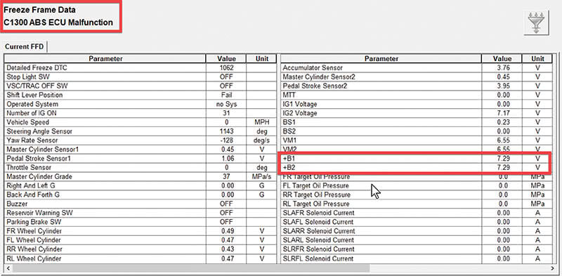
There are two types of driver brake inputs. The first are pressure sensors that measure the line pressure generated by the brake master cylinder. The brake master is a two-circuit design, as are all master cylinders made since 1967. Each circuit pumps brake fluid into a dead-end created by the master cylinder cut solenoid valves located in the ABS actuator. There are two pressure transducers in the ABS actuator that measure the pressure generated by the brake master cylinder when the driver steps on the brake pedal. Thus, the driver’s brake “feel†directly translates to the primary input for the ABS ECU, which then shares the data with the HV ECU and they negotiate the percentage of regen vs. friction via high speed CAN.
The other type of input is a brake pedal position sensor. It’s a redundant sensor with two outputs and four wires. 5V reference, sensor ground, SKS1, and SKS2. It’s the same type of sensor that’s used as a throttle position sensor on many cars. The SKS1 output goes from low to high when the pedal is pressed and SKS2 goes from high to low when the pedal is pressed. If the outputs don’t agree on the brake pedal position, a C1247 will set in the ABS ECU. This sensor is used primarily to report change in brake pedal position over time and is an important input during sudden panic braking.
Maintaining Fluid Pressure Supply
Since master cylinder pressure isn’t used to apply the friction brakes (unless there’s a system failure), the ABS system needs a constant source of pressurized fluid. This pressure is created with the ABS pump and stored in an accumulator.
The pump can be powered by either of two motor relays. The ABS MTR relay connects the pump to power through a resistor wired in series. The resistor reduces the pump motor speed for quieter operation. A second relay, ABS MTR 2, connects the pump straight to a power for higher speed operation. This system provides a way for the pump to run quietly most of the time and a way to build pressure fast if a rapid succession of braking events takes place. It also provides redundancy. If one relay or fuse fails, the other can still maintain fluid pressure.
The accumulator is a steel vessel capable of holding thousands of pounds of pressure, but it’s more than just a container.
Imagine a balloon. If you blow it up and then allow the air to escape, it will do so over a period of time, not instantaneously. This is due to the flexible nature of the balloon. A steel vessel has no flex. Once opened, all the pressure would escape within milliseconds. That’s why there’s a sealed flexible stainless steel “accordion†filled with pressurized with nitrogen inside the accumulator. When pressure is pumped into the accumulator, the accordion collapses. As pressure is released, it expands, mimicking the same effect as with our imaginary balloon.
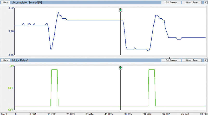
The ABS ECU needs to know how much pressure is stored in the accumulator so that it knows when to cycle the ABS pump motor on and off. An accumulator pressure sensor located in the ABS actuator provides a pressure reading to the ABS ECU.
Applying Pressure to the Calipers and Wheel Cylinders
The Prius controls pressure to the calipers and wheel cylinders using a set of eight “linear valves.†I once imagined that they were called linear valves because they were “of or related to lines,†as in brake lines, but this was wrong. Linear valves are a type of fluid or air control valve that have this characteristic: the amount of fluid that flows through the valve is directly proportional to the opening of the valve. In other words, if the valve is opened 15%, it will flow 15% of its maximum flow rate. 60% open means 60% flow rate, and so on.
There are two linear valves per line, found in the brake actuator. Both valves have one side connected to a line leading to a caliper or wheel cylinder. The other side of the valves each lead to a different place. One connects to pressure from the accumulator. The other leads back to the brake fluid reservoir. Toyota’s valve naming convention is a little hard to parse, but it’s worth knowing. Let’s say we’re talking about the left front wheel’s valves. A valve labeled “SLAFL†would be Solenoid Linear Accumulator Front Left, and a valve labeled “SLRFL†would be Solenoid Linear Reservoir Front Left.
Line pressure to each wheel is controlled individually with its two linear valves. The ABS ECU opens the accumulator (pressure) valve to increase line pressure and opens the reservoir (release) valve to decrease the pressure. Because of the proportional flow characteristics of the linear valves, the ABS ECU can precisely modulate the pressure to any wheel for as much or as little braking as needed.
Feedback Loop
We’ve discussed how the ABS actuator controls pressure to each wheel, but how does it monitor the pressure? There are pressure sensors for each brake line found inside of the brake actuator. The ABS ECU watches the pressure and adjusts the linear valves until the target pressure is reached.
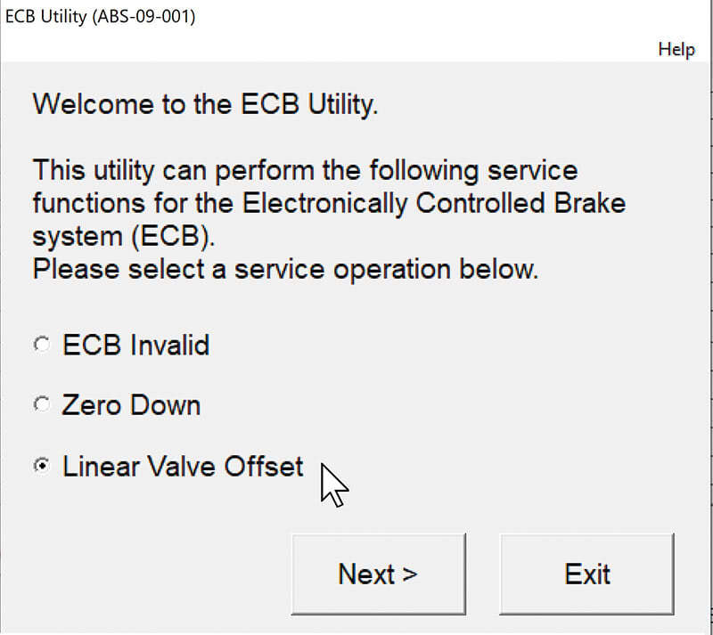
This brings up an important point. It takes a little time to learn how things respond. Have you ever watched a customer pull away from the curb after installing a new clutch? The friction point is in a different place than it was when they dropped the car off in the morning. They look like a student driver until they adjust. The ABS ECU needs to adjust to the brake actuator. Each actuator and each car are a little different. A learning procedure is required any time an ABS ECU or actuator is replaced, or the learned data is erased. If you ever run across a “Linear Solenoid Valve Offset Learning Undone,†clearing the memory and performing the learning procedure is necessary.
Occasionally you’ll find that you won’t be able to complete the learning procedure. During the learning process the ABS ECU attempts to hit and hold target pressures on each line. If the actuator is worn and the valves are sticky, the ABS ECU may not be able to hit its targets, and the calibration may fail. You can repeat the calibration process several times, and it may eventually complete, but if not, the only solution is a new actuator.
Regen Negotiation
Regenerative braking is the primary advantage of hybrid vehicles. Of course, being able to use a more-efficient less-powerful Atkinson cycle engine is also pretty major, but regen braking is the most important reason for hybrids. On a conventional vehicle, you’re wasting fuel every time you step on the brakes. A hybrid lets you keep some of the energy that would have been lost as heat.
When the driver steps on the brake pedal, the ABS ECU measures the driver’s braking request. The ABS ECU then asks the HV ECU to provide regen braking in that amount. The HV ECU then responds with the amount of braking it can provide, and the ABS ECU makes up for any deficiency by applying the friction brakes. With fast computing and networking, this all happens over and over so fast, that it’s absolutely seamless from the driver’s perspective.
There are times when the HV ECU cannot provide enough regenerative braking. One issue is the maximum braking torque of the MG2. Just as motors have a maximum power output, they also have a maximum generation capacity. How powerful the motor is affects how much reverse torque it can generate, so there are limits to how much stopping power it has.
Another issue is battery state of charge. If the battery is fully charged, there’s nowhere to put any of the power generated by the MG2, and regen braking is impossible. However, with the vehicle shifted to “B†mode, the MG2 will drive the MG1 to turn the internal combustion engine for engine braking, so even when the battery is fully charged, the load on the friction brakes can be reduced a bit to avoid overheating on long downhill drives.
Finally, the MG2 can’t provide much torque when spinning slowly, so the friction brakes are used exclusively at speeds under 5 MPH.
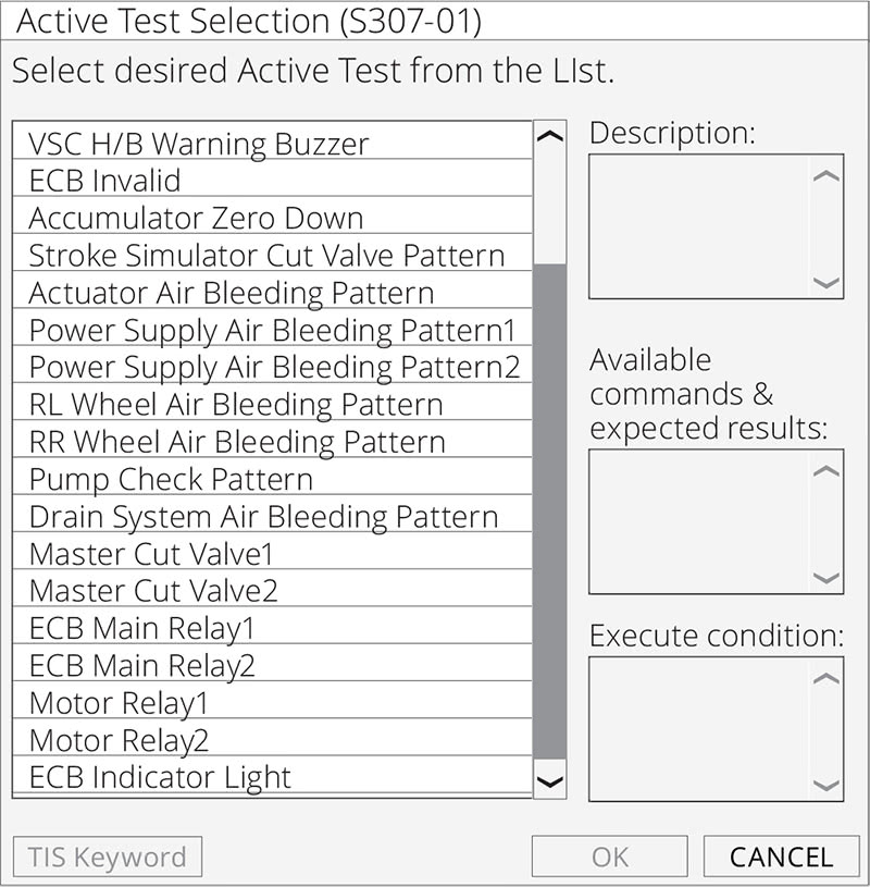
Active Tests
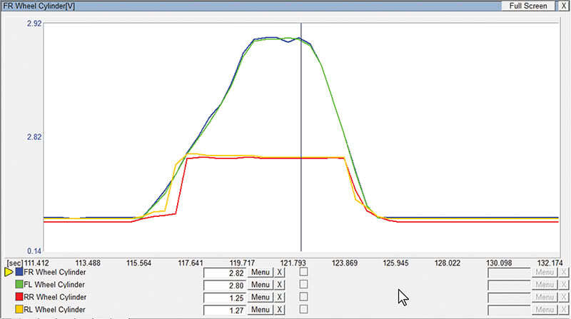
The Techstream has active tests to perform many functions. Some are more like utilities and duplicate functions found in the utilities menu. However, most are designed to aid in diagnosis. You have access to all of the wheel cylinder pressure sensors, the accumulator pressure sensor, and the two master cylinder pressure sensors in live data. The utilities allow you to operate the pump, open and close valves, and check warning outputs, all while monitoring live data, checking voltages, or just listening and looking.
The End
That’s it. Now you know how it works. The driver has a “normal†brake feel thanks to the master cylinder and stroke sensor. In the heart of the system, the brake actuator, master cylinder pressures, accumulator pressure, and individual line pressures are measured. Fluid pressure is created and stored by the pump and accumulator, and the pressure is individually delivered to each wheel. Most of the brake logic is in the ABS ECU, but it negotiates with the HV ECU to split the braking load between regen and friction seamlessly.
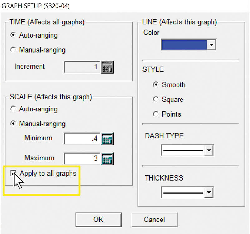
Using a Techstream, you can monitor and graph all of the input sensors, control all outputs, and use utilities for any service work.
For more information on Techstream or Toyota approved equipment visit www.techstreamsupport.com or call 1-800-368-6787.
By Paul Cortes
0 Comments