
Toyota created a “shiftâ€-by-wire system and a park-by-wire system for their hybrid vehicles. We’ll explore how the park by wire system works.
When you park your car on a hill, you’d like it to still be there when you get back. A runaway car is very bad. The car can be damaged. Other property can be damaged. And most importantly, people could be hurt or killed.
The parking brake will hold the car in place, but just in case something goes wrong, it’s nice to have a backup. All cars since 1965 with automatic transmissions have a parking pawl to lock the drive wheels and prevent them from moving. A parking pawl is a pin or lever that engages with a parking gear mounted to the transmission output shaft. When the pawl moves into the gear teeth, it locks the output shaft, so the drive wheels won’t turn.
The most common way to engage the parking pawl is with a cable connecting the shift lever to a lever on the transmission which in turn moves the parking pawl into position. Toyota did away with the shift lever and created a “shiftâ€-by-wire system and a park-by-wire system for their hybrid vehicles. In this article, we’ll explore how the park by wire system works.
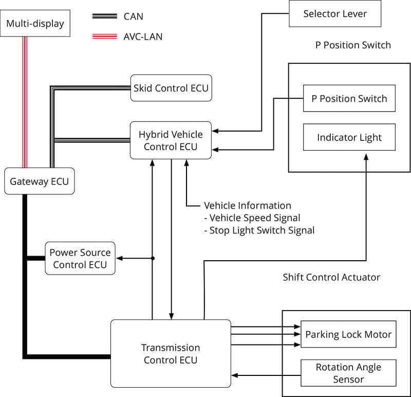
The transmission control ECU is the heart of the system. Its only purpose is engaging and releasing the parking pawl. It has nothing to do with controlling the ratio of engine speed to vehicle speed. That’s all handled by the Hybrid ECU. Instead, it drives the park pawl motor, monitors its position, sends data to the Hybrid ECU and Power Source ECU, controls the park indicator light, and receives commands from the Hybrid ECU.
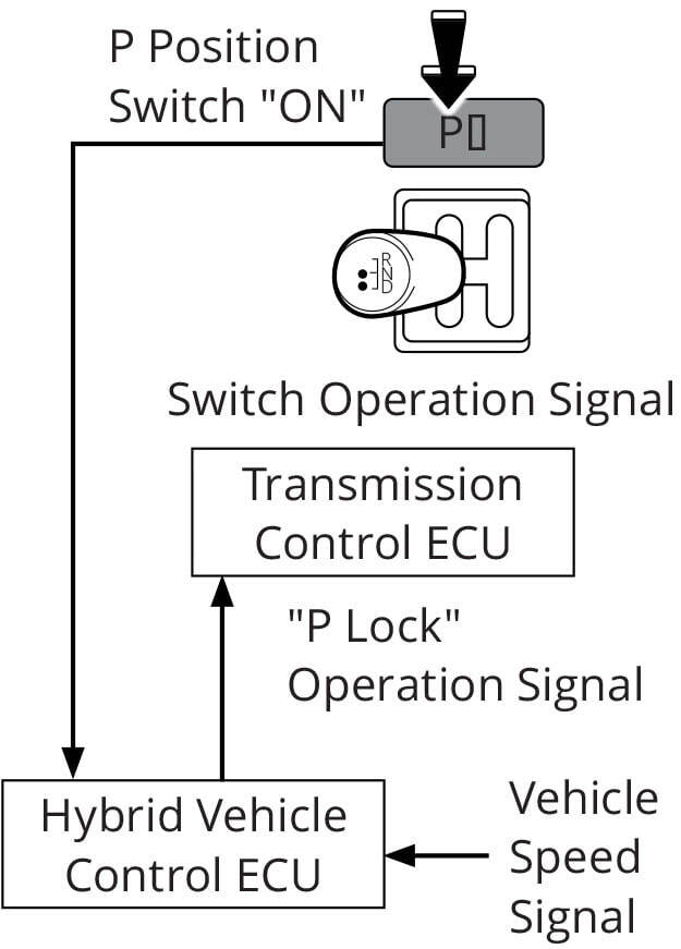
Park Button Pressed
When the driver presses the park button on the dash, the Hybrid ECU receives the signal, after checking that the vehicle speed is 0 MPH, it commands the Transmission Control ECU to engage the parking pawl.
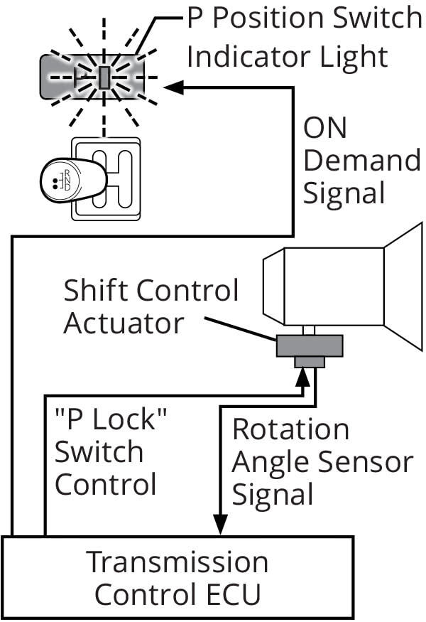
Confirmation of Park
The Transmission Control ECU drives the park pawl motor and monitors the parking pawl rotation angle sensor signal to determine if the car is in park. Once successful, it illuminates the park LED on the park button.
Toyota hybrids won’t Ready unless the vehicle is in park, the driver’s foot is on the brake, and the steering lock (if present) is unlocked. The Prius cannot be Ready’d in neutral like other cars, so a working park-by-wire system is essential.
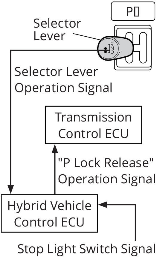
Shifting Out of Park
When the driver moves the shift lever to drive, reverse, or neutral, the Hybrid ECU receives the input, checks that the driver’s foot is on the brake pedal, and then commands the Transmission ECU to release the parking pawl.
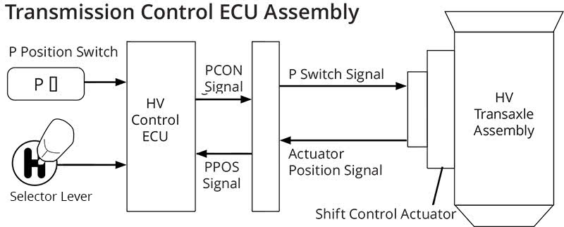
Let’s put it all together and talk about how this all happens. The HV ECU receives an input from the park button. It sends a message on the “PCON†wire to the transmission control unit (TCU), telling it to shift to park. The TCU drives the 3-phase motor in the actuator and monitors 3 hall sensors that detect rotation. When the TCU is satisfied that the transmission is in park, it alerts the HV ECU of the success via the PPOS wire, and then the HV ECU turns on the park button LED.
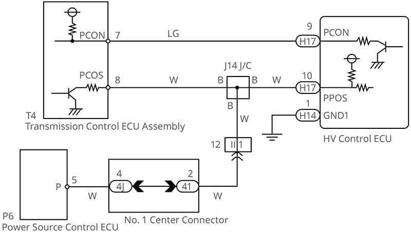
How do the TCU and HV ECU communicate? It’s network communication, but it’s a type you may not be familiar with. Most network communication is “duplex,†meaning messages can be sent and received on the same network connection. The TCU and HV ECU use a “simplex†network. On the PCON wire, the TCU provides a 5V regulated voltage and “listens†when the HV ECU pulls it to ground with a transistor. Only the HV ECU can talk on the PCON wire. For the PPOS wire, the HV ECU provides a 12V regulated power supply and “listens†to what the TCU is saying. The Power Source ECU also eavesdrops on the PPOS wire to find out if the car is in park.
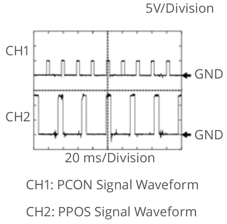
Here we can see what the PCON and PPOS look like. The service manual has an example waveform, and as you can see signals match. Oscilloscope testing is a much better option than checking wires with an ohmmeter. First, you only need to access one end of the wire to know the wire is OK. Second, you’re looking at the wire while it’s handling the signal it was designed for. Third, you can tell if the power supply is coming from one unit and if the signal control from the other unit is good. All this in less time than it would take to do a resistance test.
We’ve covered the connection between the HV ECU and the TCU, now let’s take a look at the TCU and the shift actuator.
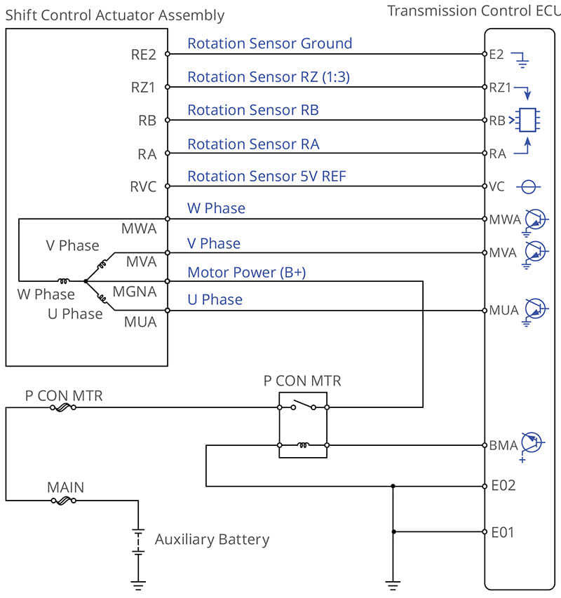
12V is fed to the center tap on the 3-phase actuator motor stator through the PCON relay, which is controlled by the TCU.
The TCU alternately grounds the three phases through transistors to make the rotor spin.
The TCU monitors rotation using hall effect sensors mounted near the rotor. The rotation sensor has three outputs: RA, RB and RZ.
RA and RB pulse three times per rotation and RZ pulses once per rotation.
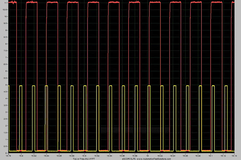
This oscilloscope capture has four signals. Since most oscilloscopes have only four channels, it makes sense to exclude the W and V phases from the capture in favor of including all three rotation sensor signals.
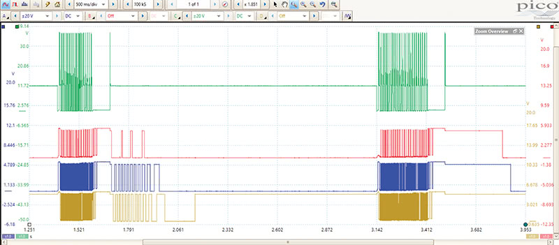
On the top, the green trace is the U-phase signal from the TCU to the 3-phase motor. You may notice that the voltage is quite high—around 40V. This is just a 12V motor though. The high voltage peaks are just spikes from the magnetic field collapsing as power is cut to the U-phase winding.
The red, blue, and yellow traces are the rotation sensors. The red trace is the RZ signal, so there are fewer peaks, since it produces only one pulse per rotation. The blue is the RB signal and the yellow is the RA signal. Both RB and RA produce three pulses per rotation.
In this capture, the parking pawl is released, then after about 1 second, it’s re-engaged. You may notice that in the first series of pulses the motor is driven (green trace), held for a moment, and then released. When the TCU stops holding the motor, it spins on its own (red, blue, and yellow traces). This is due to a detent sucking the parking pawl into position away from the output shaft sprocket.
When the motor re-engages the parking pawl, it must drive the motor the entire way home.
Using the Pico Scopes rulers, we can easily count the pulses, which is what the TCU is doing to figure out whether park is engaged or not.
When park is released, the U-phase is pulsed 26 times, held a moment, then released. The RB rotation sensor pulses 74 times, pauses, then pulses another 12 times as the pawl is sucked into its released position by a detent.
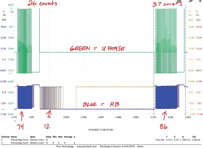
When park is engaged, the U-phase pulses 37 times and the RB rotation sensor pulses 86 times. On the way out of park we have 72 pulses on RB while the TCU drives the motor, and then 12 pulses while it was being moved by spring tension for a total of 86 pulses. The rotation is the same when releasing and engaging park, the only difference is that the TCU doesn’t drive the motor all the way into the released position.
Notice how the TCM stops driving the parking pawl but then it continues moving? This is the detent being sucked into position by the spring lock. Using this information, you can tell if the detent is working properly. If the motor doesn’t continue to spin when the TCU stops driving when park is released, there’s something wrong with the detent.
We hope you’ve enjoyed this walk through [the] park. It would be very difficult to diagnose this system if you didn’t know how it worked, but hopefully you have a better understanding now; if you forget some of this information before you next need it, don’t worry. Toyota has these systems well documented in the service information. Just remember to pay attention to the direction of the arrows in the conceptual diagrams and to leave your ohmmeter sitting in your toolbox. An oscilloscope will save you a lot of time.
0 Comments