
How it works, diagnosis and troubleshooting tips
The Mercedes-Benz Model 210 E-Class is probably a typical visitor to your shop, with a zillion still on the road, and they are getting to that age where things that are normally bulletproof start to show their age. Pneumatic central locking is one of those systems, and in this article we will have a look at how it works, along with some basic diagnosis ideas and a few tips for a faster identification of any trouble.
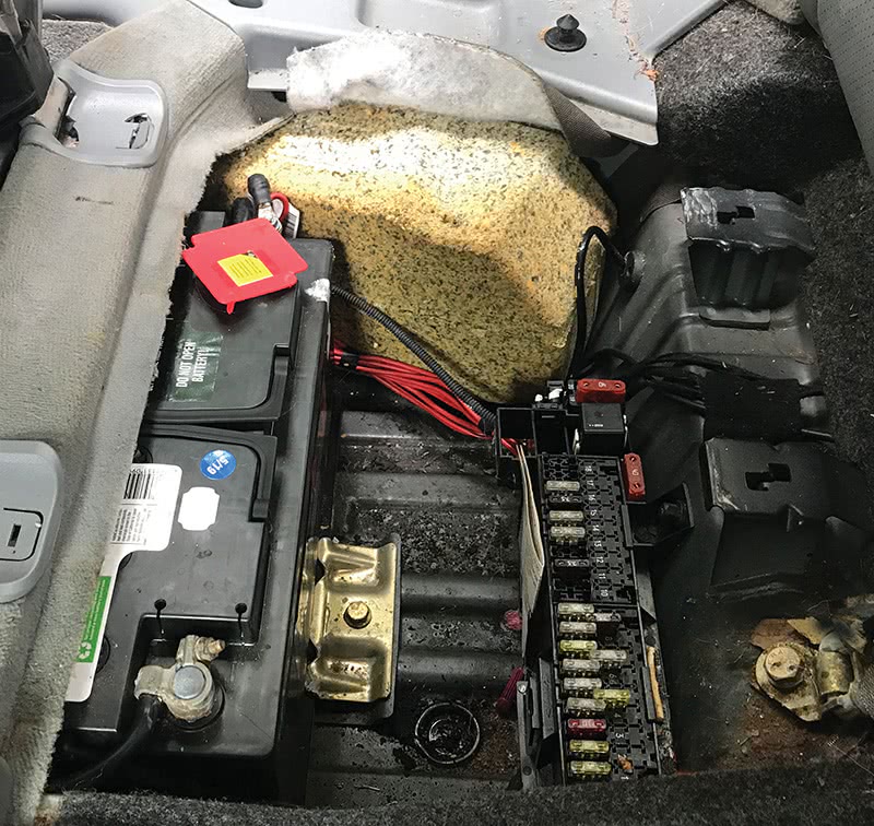
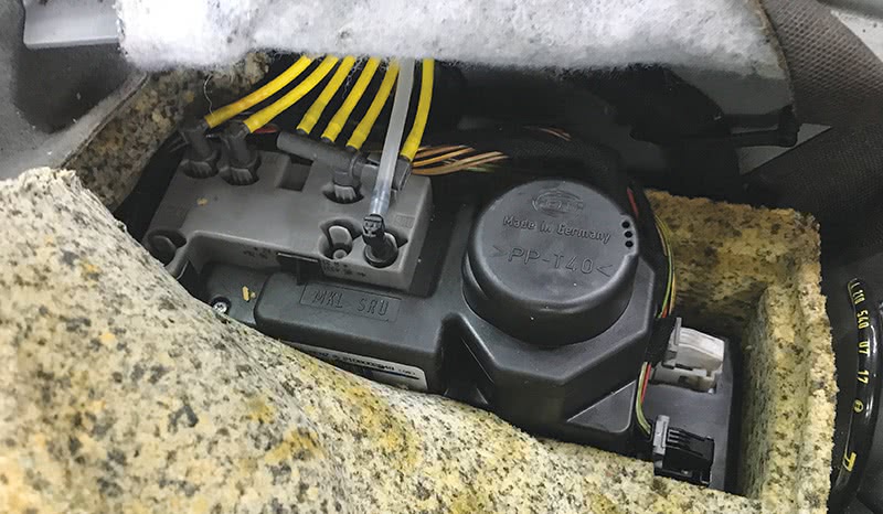
The PSE (Pneumatic Special Equipment) pump is the heart and soul of the central locking (CL) system, and is found under the right rear seat. It is responsible for several functions: Pneumatic central locking (with several sub-functions), Anti-theft alarm (ATA), Rear head rest retraction (RHR), Manifold vacuum assist (MVA), Multi-contour seat (MKS) adjustment (via pneumatic bladders), requesting the operation of certain interior and exterior lighting and unlatching the trunk lid (RTR). In this article, we’ll be mostly limiting ourselves to the pneumatic central locking function, and specifically the system found in DAS3 models (model year 1998 and later).
For most drivers, their touchpoints with the CL system are when they unlock or lock the car with the remote key or with the dash-mounted central locking switch, automatic locking at a certain speed threshold, retracting the rear head rests and opening the trunk lid in sedans. This is a system that, while certainly not essential to the vehicle’s operation, is such a convenience that most customers will want it operating properly.
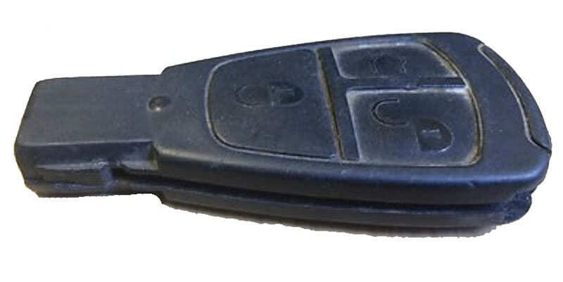
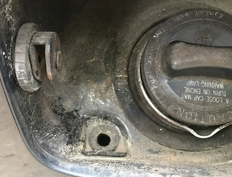
Unlocking the vehicle with a remote key fob starts when the customer presses the unlock button on the SmartKey. Depending on whether the system is set for ‘global’ or ‘selective’ unlocking (see nearby image), either all openings (doors, trunk/tailgate, fuel flap) will be unlocked in global mode or only the driver door and fuel flap will be unlocked in selective mode. A second unlock button press in selective mode will unlock all the remaining openings. If the vehicle is unlocked using the remote key, but no door or trunk/tailgate is opened, it will relock automatically after 40 seconds.
The key signal is received by either the radio-frequency (RF) receiver located in the overhead control panel (dome light, N70) or an infra-red receiver in one of the front doors. From there, the coded signal is passed via Interior CAN by either N70 or a door control module (DCM) to the Electronic Ignition Switch (EIS, aka EZS). The EIS decodes the signal and, if it is correct for the specific vehicle, sends a message via CAN to both the PSE and the driver-side SAM (N10/1).
The SAM flashes the turn signal lamps once to confirm unlocking. The PSE then delivers pressurized air to the pneumatic CL actuators, unlocking the appropriate points (selective or global) generally via a mechanical linkage (except the tank flap, which is actuated directly). For locking, which is always global, the process is similar, except that vacuum is used to operate the CL actuators and the turn signals are flashed three times. When locked from outside the vehicle, the ATA is also armed and the headlights, if switched on during the trip, will light for about 20 seconds.
Note that the EIS, remote key and other components are Theft-Relevant Parts (TRP). Anyone can order nearly any TRP from a dealer as long as you are a registered Vehicle Security Professional (VSP). Becoming a VSP is neither difficult nor expensive, but it is probably not cost-effective if you don’t usually service Mercedes-Benz vehicles. Visit the North American Service Task Force website at nastf.org to learn about and apply to get your SDRM credentials and become a VSP.
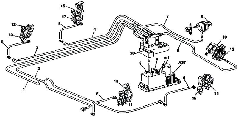
Pneumatically, there are only four circuits involved in CL: The driver’s door, the passenger’s and two rear doors, the trunk or tailgate lock, and the fuel flap. The three doors and trunk/tailgate are fed from a single PSE outlet and a multi-way connector; the driver door and tank flap have their own outlets.
Operation using the mechanical key, which is a feature only included in vehicles built for the USA and Japanese markets, is nearly the same: A switch in the mechanical door or trunk/tailgate lock actuates the system, either through the respective door control module or a direct wire to the PSE from the trunk/tailgate lock cylinder switch. Again, when locked from outside the vehicle, the ATA is armed.
The interior switch (S6/1e2) also operates the system. It is connected by a direct wire to the front SAM, which sends a signal via CAN to the PSE. Locking the vehicle using this switch does not lock the tank flap or arm/disarm the ATA. If either the driver or passenger door is open then locking via the interior switch is disabled.
Automatic locking occurs when the feature is enabled, the vehicle was initially unlocked from the exterior and the vehicle speed exceeds about 10 MPH (15 km/h). The effect is the same as if the interior switch was used. Remote trunk release is also inhibited. This feature can be deactivated and activated using the interior CL switch as follows: With circuit 15 on, press and hold the switch for longer than 5 seconds in the ‘unlock’ position to deactivate it or in the ‘lock’ position to activate it. Note that it is possible to set the version coding of the PSE (using the HHT for example) such that automatic locking cannot be activated.
If the vehicle is locked, any door can be immediately unlocked by pulling the interior door handle. This does not disarm the ATA if it was armed.
In the case where the PSE’s internal acceleration sensor detects a deceleration greater than about 6 g (e.g, in a crash), the vehicle is completely unlocked after a brief time (8 to 11 seconds). This also does not disarm the ATA if it was armed. If circuit 15 is subsequently switched off for at least 2 seconds, the vehicle returns to its state before emergency unlocking occurred. Note that the emergency opening function has priority above all other CL functions.
The PSE also controls the Manifold Vacuum Assist (MVA), Rear Head Rest (RHR) release, Remote Trunk Release (RTR) and Multi-Contour Seat (MKS) functions pneumatically in vehicles so equipped.

MVA is used to assist the automatic climate control (A/C) system flap actuators at times when manifold vacuum is insufficient. It operates when either the ignition or the REST feature is on, using a pressure switch in the PSE to determine if vacuum is sufficient. This system uses a gray vacuum hose running along the passenger side floorboard to supply vacuum to a vacuum reservoir (also connected to the intake manifold in gasoline models) hidden inside the right front fender, next to the ATA siren. If the A/C flaps seem inoperative, weak or make a thump noise, suspect vacuum supply.
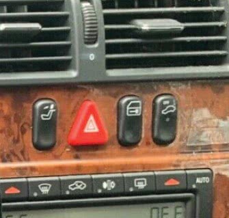
RHR uses vacuum to operate actuators at each rear head restraint, which allow the head rests to fold down into the rear hat shelf and improve the driver’s view to the rear. Head rests should always be up when a passenger is in the seat. When the switch (S6/1e3) on the upper control panel in the dash is pressed, the front SAM sends a CAN message to the PSE to operate the system when the ignition is on. The head rests can be raised by hand. If either the RHR or interior CL switch is closed for more than 25 seconds (e.g., due to a fault) the SAM ignores the switch until the switch is detected to not be closed.
RTR uses pressure to unlatch the trunk lid when the switch (S15, located near the transmission shift lever) is actuated, or when the trunk release button on the remote key is pressed. An indicator lamp in the switch indicates if the trunk is open. In MY 97 and earlier vehicles with the single-button remote, pressing the button twice within about 0.8 seconds will open the trunk lid. From personal experience, it takes a little practice to get the timing just right. Above about 10 MPH, the trunk release switch operation is inhibited.
MKS uses pressure to inflate air bladders in the driver and passenger seat using pressure. The PSE maintains a certain air pressure on the MKS pneumatic line when the ignition is on via a pneumatic switch in the PSE. A mechanical switch mounted to the seat directs the air to specific bladders to control the various functions.
Diagnosis Function Check
Before trying to repair a problem, after speaking with your customer about the complaint, check all of the PSE functions to note what does and doesn’t work. The 11 steps summarized here are from the Mercedes-Benz Workshop Information System (WIS) document AD80.20-P-3001B, which applies to Model Year 1998 and later models. After completing these steps, you should have a good idea whether the system is operating normally or not. If functions other than CL are affected, visit the MBUSA STAR TekInfo website at bit.ly/3N8io5B to access the official Mercedes-Benz Diagnostic Manual, which has function checks for other related systems.
Note: “All points†means all doors, trunk/tailgate and fuel flap, and all locking/unlocking actions should occur in less than about 3 seconds.
- Lock vehicle with transmitter key (check both IR and RF). All points lock.
- Unlock vehicle ‘selectively’ with transmitter key (pre-set the key for this) IR and RF. Driver door and fuel flap unlock. Press unlock again, all points unlock.
- Lock vehicle, then unlock ‘globally’ with transmitter key (pre-set the key for this). All points unlock.
- With vehicle unlocked, enter vehicle and close all doors. Press interior CL switch to lock. All points lock except fuel flap.
- Press interior CL switch to unlock. All points unlock.
- In ‘global’ opening mode: Lock vehicle with interior CL switch, then open a door from inside. Door opens and all other points unlock.
- In ‘selective’ opening mode: Lock vehicle with interior CL switch, then open a door from inside. Only actuated door opens and unlocks.
- Lock vehicle using mechanical key (USA/Japan only) at doors and trunk lid. All points lock.
- Unlock vehicle using mechanical key (USA/Japan only) at doors and trunk lid. All points unlock.
- Lock then unlock vehicle using remote key. Wait about 40 seconds without touching the vehicle. All points re-lock.
- Unlock vehicle and drive it above about 10 MPH. All points except fuel flap lock. Note: It is possible this function is deactivated either via the interior CL switch or via version coding the PSE.
Testing
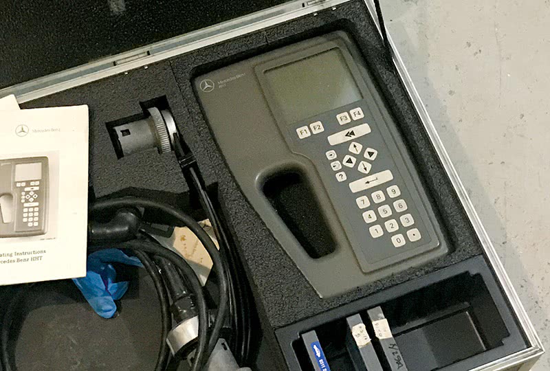
The PSE has a fault memory and can deliver Diagnostic Trouble Codes (DTCs). The PSE is diagnosed with the Hand-Held Tester (HHT), so most aftermarket testers won’t be able to read the DTCs, but any XENTRY Diagnostics system (possibly needing an adapter) fully supports all HHT functions. Disconnecting power from the PSE for about 3 seconds erases the DTC memory. A complete list of the possible DTCs can be found in the official Mercedes-Benz Diagnostic Manual, available to everyone at the MBUSA STAR TekInfo website bit.ly/3N8io5B.
The Actual Values screen on the HHT is very helpful when determining if a given electrical signal is making it to the PSE. Simply display the desired actual value on the HHT screen and actuate the switch; the switch status is displayed.
To properly test the pneumatic system, you need a good source of vacuum and pressure. The Mercedes-Benz pressure-vacuum pump (W201 589 13 21 00) is an excellent investment, but you might find something similar in the aftermarket. Whatever you choose, it must not exceed 1-bar pressure or vacuum and be equipped with an accurate gauge.
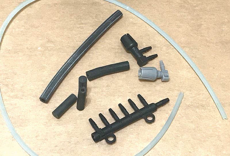
A set of pneumatic system fittings, lines and plugs will also prove helpful. We suggest visiting your dealer to get a couple of plugs (A202 805 03 44, A202 805 04 44), rubber caps (A000 997 11 45), some rubber hose connectors (A007 997 61 82), a pneumatic line (A129 800 95 15) and a meter or more of vacuum tubing (A000 158 14 35).
Optional but useful are the Socket Box (W124 589 00 21 00) and adapter harness (W202 589 15 63 00), along with the Mercedes-Benz Electrical Connection Set (W201 589 00 99 00 or later). These allow you to easily complete the electrical testing routines described in the Diagnostic Manual with no chance of damaging the wiring. Of course, a good multimeter and someone who knows how to use it is always handy.
And even though it should go without saying: Remember the basics. If the pump isn’t working at all, check for DTCs first if you have the ability, and only then check for power (including the fuse!) and ground. If only a certain function isn’t working, check that area both electrically and pneumatically. Remember that a new PSE needs to be version coded or it may not function as expected.
Troubleshooting Tips
If nothing works, read the DTCs if possible (before checking power!), then reset the PSE by temporarily disconnecting power. If functions return to normal (or nearly so), suspect a larger leak, which sets the pump into safety shutdown. Listen for the pump running excessively. Safety mode in most PSE versions occurs after 10 ignition cycles with a large leak.
The pump itself should be able to deliver 600 mBar of pressure or vacuum. Less than that indicates a weak or internally-leaking pump.
If the doors lock properly but are slow to unlock you need to check all the rubber pneumatic connections for splits. A split is like a pneumatic diode: It allows pressure (unlock) to leak out, while self-sealing under vacuum.
If the trunk lid doesn’t open when released, check if the trunk seal is adhering to the trunk lid. This can be cured with a light coating of silicone spray or grease.
Each actuator has its own hose. The driver door has its own pump outlet and fitting, as does the tank flap, while the other three doors and the trunk/tailgate share an outlet and have a 4-way fitting. Disconnect and test them one at a time. In most cases the three lines are marked A, B, C for LR, RR and RF door.
Pneumatic lines must be completely leak-free. With the far (actuator) end plugged, apply 600 mBar of both pressure and vacuum. The reading must not change at all (zero mBar) in 60 seconds for both tests.
Pneumatic actuators have a slightly less stringent test standard. Connect your tester directly to the actuator, apply 600 mBar pressure and vacuum, in each case there must be less than 30 mBar leakage in 60 seconds. Actuators not meeting the test value must be replaced.
Your ears can be excellent diagnostic tools. Pressurize a circuit and listen for the leak (it needs to be pretty quiet for this). This might help you avoid removing much of the interior.
If a line needs replacement, just run a new one, leaving the old one in place. Since lines are generally incorporated into the wiring harnesses it may be both extra work and adding a risk of harness damage if you try to remove it.
If a circuit passes the pneumatic tests, but still has trouble, look for mechanical issues between the actuator and the mechanism. This is about as common as a failed actuator.
If the system operates, just not using the remote key, first make sure the key batteries are good, then synchronize the key by inserting it into the ignition switch.
Version Coding
All PSE pumps require version coding at installation. This list shows all possible coding possibilities, but note that some options are not included with certain PSE versions. Always use the correct part number PSE for your specific VIN. The defaults for the USA are underlined.
- Automatic locking (Yes/No)
- Relocking (Yes/No)
- Locking via interior CL switch (Yes/No) (Only relevant if Autom. locking is Yes)
- Alarm siren installed (Yes/No)
- National Variant of ATA (Rest of world/USA/Belgium) (USA setting allows delayed headlamp function)
- Interior motion sensor (Yes/No)
- Anti-towing sensor (Yes/No) (Default depends on model year)
- Panic alarm (Yes/No)
- Special protection vehicle (Yes/No)
If you don’t have the capability of version coding a PSE, your dealer should be able to help. All XENTRY Diagnostics systems have full HHT capabilities. An adapter is needed, available from MBUSA. While it’s not a standard part of the Kit 4 system, it is relatively inexpensive and readily available.
This concludes our tour of the Model 210 E-Class version of the pneumatic central locking system. With this knowledge you are able to better understand how the system works, so that you can perform a professional diagnosis using your observation of the symptoms and come to a faster conclusion as to the root cause of the complaint. Some common faults and their cure were given, along with some of the head-scratchers.
In this business we all know that time is money, so a fast and accurate diagnosis is good for everyone. Understanding why the fault occurred helps us make a permanent repair, making our customers happy while increasing the shop’s business. And, isn’t that the ultimate goal?


0 Comments