
It’s in the Air Around Us
Today’s Mercedes-Benz vehicles use many different RF (Radio Frequency) and IR (Infrared) based devices for communications in several of their vehicle control systems. RF and IR signals touch just about every system onboard today’s car. Diagnosing the RF systems can be a real mystery and can become necessary when conventional diagnostics and module replacements don’t bear out the fault.
While too numerous to list, some of the RF and IR systems used in Mercedes-Benz vehicles include: KEYLESS-GO, Infrared remote entry system, TPMS (Tire Pressure Monitoring System), the Electronic Ignition Switch (EIS) and Drive Authorization, PARKTRONIC, Night View Assist, DSRC (Dedicated Short Range Communications), Bluetooth, GPS navigation, radar adaptive cruise control, Bluetooth connectivity, proximity sensors and yes, even the audio, in-vehicle telephone comms and infotainment systems all utilize RF in their functions. Suffice it to say, RF is with us, around us and will continue to play an expanding role in data transfer, communications, security, autonomous driving features and Pre-Safe safety systems in Mercedes-Benz vehicles.
Yet, we technicians are not generally taught the principles of RF or IR, how it works, what it is and how to measure and quantify its presence. As automotive technicians, we’ve lived our lives up until now in a linear DC world. This is changing at a rapid pace, and techs must stay on top of the technology we work on to the best of our abilities.
Understanding and testing of RF systems are now becoming necessary skills for a technician who chooses not to become the victim of diagnostic nightmares brought on by the mysterious Hertzian Hooliganism we don’t understand. In Mercedes-Benz vehicles, diagnosing RF issues is a common thing, albeit mostly done now with data analysis via scan tool, a multimeter and the Mercedes-Benz special tools for RF and IR diagnosis. Nonetheless, from time to time we’ve found that we need to go deeper than this to get the answer. This is where becoming a student of RF becomes really handy as a tech.
Fun Fact: Radio wave is a term coined in 1912, which sticks until this day. Prior to 1912, these were known as Hertzian waves, after Heinrich Hertz (1857-1894) a German scientist who first proved their existence.
What is RF?
Radio frequency energy consists of propagating electromagnetic waves, oscillating at certain frequencies and resonant phase angles. Phase angle refers to the relationship between the waves generated in the magnetic field, versus that of the electric field. (See Figure 2.) A radio wave must have both an electrical and a magnetic component.
Electric and magnetic fields are used to produce, transmit and receive RF and IR messages, including data, voice, video, and other signals. As these oscillations are radiated into the atmosphere by being driven from the transceiver’s antenna, the waves can travel either very short distances, such is the case with automotive transponders, or very long distances such as High Frequency and Shortwave, where signals can travel thousands of miles.
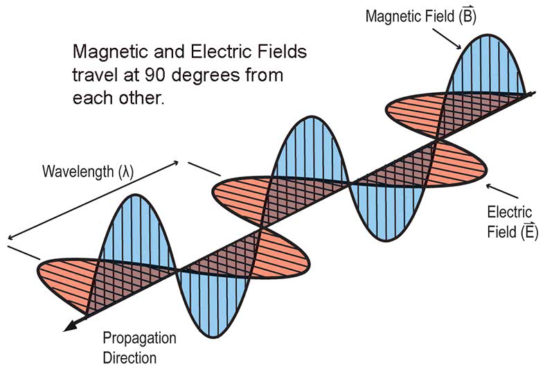
It was discovered that electric fields had an effect on magnetic waves, and magnetic waves had an effect on electric field waves. Once this activity is put into motion in the form of a transmitted radio message, these radio waves travel at the speed of light in space. (In air, it’s a little slower, on a wire it is slower still, but definitely very fast regardless.)
The wavelength is determined by the distance between peaks of the wave, usually specified in meters. This is calculated by dividing the speed of the wave (about 300,000 kilometers per second in air) by the frequency of the wave. Broadcast FM radio has a wavelength of about 3 meters.
The distance over which a radio wave can be detected depends on several factors, including the frequency, atmospheric and solar conditions, as well as the characteristics of the radio transmitter and receiver.
The Frequencies
Radio frequencies are measured in cycles per second, or Hertz (Hz). The US Federal Communications Commission (FCC), who has responsibility in the United States for spectrum allocation and regulations, defines radio frequencies as spanning from 9,000 Hertz (9 kHz) to 300 GHz. Note that 9 kHz, when converted to sound waves, can be heard by most humans. Who can use which frequencies, and for what, is strictly controlled by governments worldwide, and penalties for non-compliance can be severe. The chart (Figure 3) shows the wide span of radio frequencies and their uses in the United States.
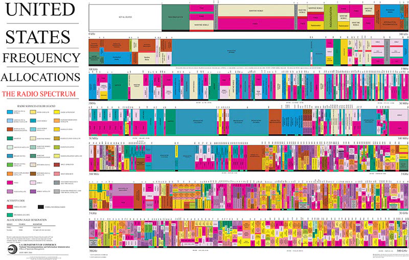
In Mercedes-Benz vehicles, we have several of these bands in use. Specifically, VLF (Ultrasonics), LF (Transponders), VHF-UHF (RF Remotes), SHF (Wi-Fi and Bluetooth) and EHF (Radar Adaptive Cruise Control). Above the Radio Frequency Spectrum, at frequencies measured in Terahertz (THz) lies the Infrared spectrum, which Mercedes-Benz utilizes heavily in their wireless communications scheme.
In the automotive realm, our RF bandwidths are relatively narrow, meaning we are confined to certain frequency ranges where only certain devices are allowed to transmit and receive. An example of this is the RF remotes for the door locking systems. These automotive devices must operate at one of three frequencies worldwide, 315 MHz (most common in the USA), 433.9 MHz (Primarily Europe) and 868 MHz.
Finding the Signals and Pulling Them Out of Thin Air: The Dark Arts Part of RF
In Automotive platforms, most RF devices are relatively short range, meaning your Keyless-Go remote will not be heard in the Netherlands when it transmits. RF energy, power, modulation and measurement are a lifelong study, even for engineers. As fellow automotive techs, let us welcome you to the Electronic Dark Arts.
Frustration can come quickly for the uninitiated tech; RF is difficult to measure and verify unless you (A) have the right pre-designed equipment such as a Mercedes-Benz RF tester or (B) you have enough curiosity and creativity to design your own tools and methods. Or, you can simply use the many existing tools available for sniffing RF signals out of the air. That’s the complicated part that requires a bit of study.
As techs, we are used to linear DC electrical measurement, so the concept of an RF sniffer for a scope and a demodulator circuit are foreign to most of our brains. Sampling RF on an oscilloscope is relatively easy with a homemade or commercially available RF sampler circuit, once you know what you are doing.
We have found several cool tools out there that can help detect the presence of RF, and several more advanced tools and methods for demodulating and decoding the RF signals from automotive platforms without crazy expensive tools.
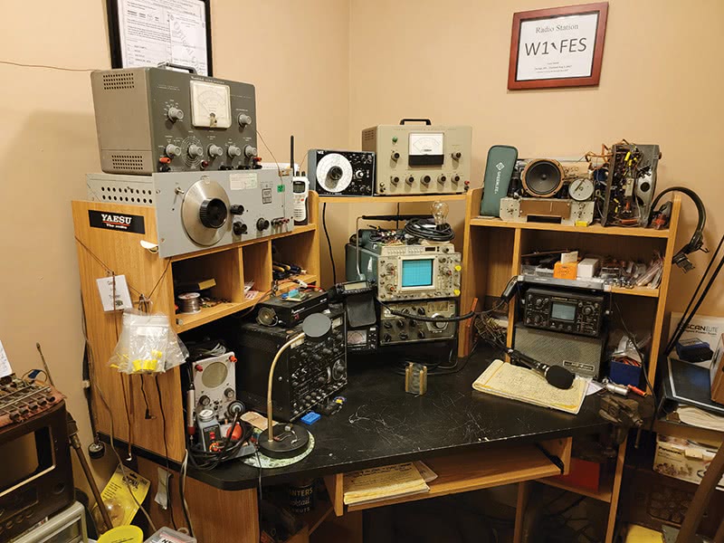
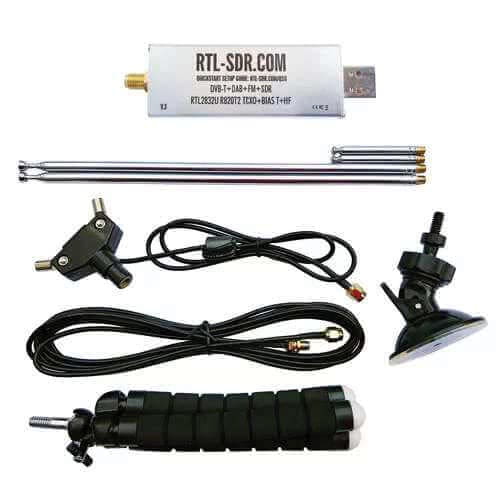
One really neat setup for this is a $40 USB dongle setup that contains a Software-Defined Radio (SDR) and dipole antenna kit. Connect the dongle to a computer’s USB port, install the software, and you have a general-purpose wideband receiver (see Figure 5). While not an approved Mercedes-Benz special tool, this wide-band general purpose receiver is popular with electronics hobbyists. Visit rtl-sdr.com to buy one, but beware: The genuine “RTL-SDR Blog” brand is the one you want, avoid other brands on Amazon as they often perform poorly. This cool setup is what we use to quickly detect the presence of RF keyless remotes, ultrasonic sensors and anything emitting RF energy on most frequencies encountered in automobiles.
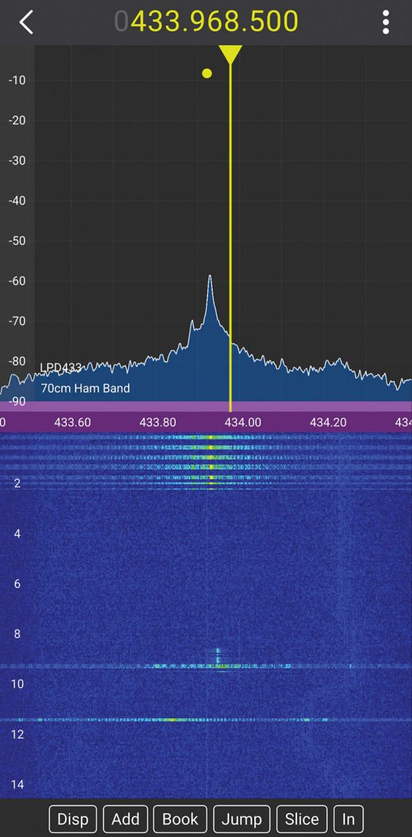
With everything installed and configured according to the instructions, select your frequency range and press the remote button. The device nicely captures not only the remote’s transmission to the car, but also receives and visually confirms the chirp-back burst from the vehicle to the remote for authentication. This is a handy tool to have to verify many automotive RF systems. Once you identify an operating frequency for any RF emission, you can name and save it to use frequently.
Regardless of which tool you are working with, remember that the positioning of the antenna is important, so when testing for any RF emission, it sometimes becomes necessary to change the angle of the antenna or device to get the best reception. These are the little differences between what we usually test and expect, versus testing for RF in the air.
Let’s briefly review a few types of IR and RF systems and identify some general points and testing possibilities for the aftermarket shops sans Mercedes-Benz special tools.
Hint: These vehicle systems, by virtue of FCC band allocations, all operate in the same ISM band ranges, so this discussion covers most all other makes of cars too, not just Mercedes-Benz.
Infrared for door locking and Start Authorization: Quick tips for testing function.
Mercedes-Benz has historically used Infrared for their remotes and for smart key wakeup and authorization. These signals can be tested using the Mercedes-Benz IR-RF Special Tools along with a scan tool to verify signaling is taking place. However, few non-dealer shops that have the Mercedes-Benz special tool. Instead, we can utilize a few tricks to measure the presence of these signals, and to test the Infrared portion to ensure it is working too.
We can use a couple of different creative methods here: The first and easiest way to see if the Infrared transmitter is working on the vehicle is to take your cell phone camera, simply point the Infrared remote window at your camera and press each button, one at a time. The cell phone camera will detect the Infrared signal as a blueish/greyish glow when transmitting. We can use this method to verify the function of the transmitter itself and often the ignition switch side. However, this test cannot tell us if the signals sent are properly coded.
For this, we would need to utilize the scan tool to verify authentication of signals, or if debugging, we would need to capture and demodulate the signal through an RF sampler, couple the signal into a scope and decode the messages to confirm correct information was being transmitted back and forth. Because the specifics of these signals are confidential information, this is not going to be terribly useful.
Always consult the Mercedes-Benz WIS to get the details of the system on which you are working, including the function description and circuit diagram, to best understand how the system works and which signals you must verify under testing conditions.
Radio Frequency VHF-UHF and Keyless-Go Remote Transmitters (Door locks, Wake-up)
Most automotive RF remotes work at 315 MHz in the U.S., 433.9 MHz in Europe and in the recently allocated 868 MHz bands. ISM frequency allocations can be found throughout the entire radio spectrum, from shortwave frequencies to beyond microwaves. Unlike most frequencies, ISM frequencies don’t require the user to be licensed, but the devices that operate on the ISM bands are strictly regulated. For testing the remotes there are several options.
If one searches the internet, one can purchase any number of prebuilt RF or IR remote and transponder testers in the $200-$700 range. Some of these products will measure nearly all of the RF signals emitted from vehicular platforms, except perhaps radar units. These tools are great to have, whether you are a dealer tech or an independent garage.
Another method is to buy or build an RF probe. By forming a loop with the tip and ground lead of an oscilloscope probe, we create a simple antenna. We can then place the remote in the loop and press any button to display the RF signal on the scope screen. Now let’s be clear here, it is highly unlikely you will actually be able to make use of the decoded signals, as the coding of the signals are unpublished and proprietary, but we will be able to verify transmission and reception nicely, meaning techs can actually verify that the device is working, which is really all we need for diagnosis on any of these systems.
The fact of the matter for technicians is that if the RF device is signaling and the antenna side is verified, any inoperability will become either a coding, data corruption or software issue, which is well beyond the scope of this article. In most cases, this will involve both component replacement, and running of the proper programming, SCN or Variant coding, depending on what you are working on at the time.
Very Low Frequency Transponders (IMMO and TPMS)
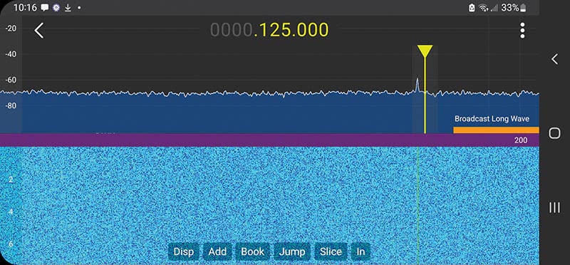
Transponders (Transmitter-Responders) are very low power radios in automotive platforms, typically used for immobilizer and Drive Authorization systems. These use frequencies of 125kHz or 134kHz but only at a fraction of a watt of power. Detection of these signals requires a powered transponder to excite the signal, and an amplifier module to receive and decode the signal. A key transponder sends a coded response when interrogated by the vehicle or testing device. There are many transponder testing tools available for the automotive aftermarket.
Controlling functions
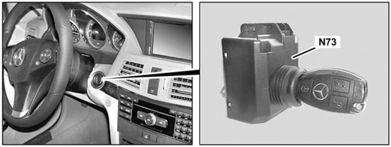
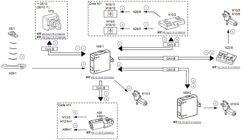
The elctronic ignition lock control unit actuates the following functions:
- Central locking (CL)
- Convenience feature (CF)
- Drive Authorization System versions 3 and 4 (DAS 3/DAS 4).
When the transponder in a key is placed in the ignition switch, a coil surrounding the key head delivers a small amount of electrical energy to the transponder (at around 125 kHz), just enough for it to transmit its authorization request. This means that even with a dead battery the key can be used to start the engine.
However, to unlock the vehicle, the key battery must have enough energy to operate the key’s transmitter. The receiver in the vehicle uses an amplifier to strengthen and partly decode the signal received before passing it on to the unlocking system. The amplifier knows the ‘vehicle code’, which is unique to the vehicle but not a secret, and filters out any received signals that don’t have the correct code. In this way, the system can ignore everyone else’s key fobs in the mall parking lot. If you are monitoring the signal output from the amplifier and use the wrong key, you won’t see any output and might possibly (but incorrectly) conclude the amplifier has a problem.
Ultrasonic Sensors
Ultrasonic (high-frequency sound) sensors are used for parking assist, proximity sensing and other uses in PARKTRONIC and related systems. These typically pulse energy out at a frequency of 40 kHz to 60 kHz, listening for the resulting echo from a hard surface to sense distance. Here, we can use a cell phone spectrum analyzer app to detect these signals. Remember, the car must be in gear for these sensors to operate, and in reverse for those in the rear bumper. We usually have a tech creep the vehicle forward and backward as we test each bumper sensor.
DSRC V2V and V2I Radio Comms
Dedicated Short Range Communications (DSRC) platforms, V2V, V2I and V2X communications occur in the 5.49 GHz to 5.79 GHz range. These radios communicate with other vehicles on the road (V2V) as well as with the infrastructure (V2I) and other systems (V2X). These cool systems allow your vehicle to send and receive messages for collision avoidance, traffic and freeway loading infrastructure. DSRC is an optional accessory in Mercedes-Benz vehicles.
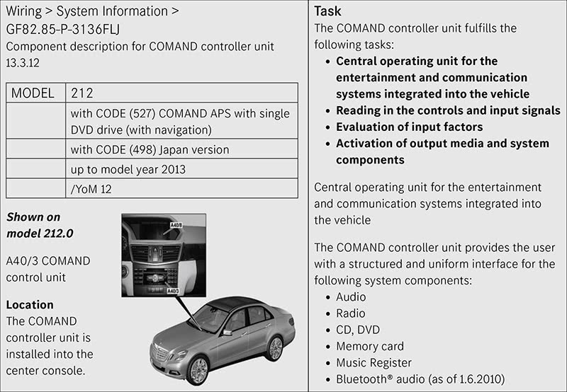
Bluetooth, Wi-Fi and Cellular Radio Modules
Bluetooth is a low power interface. Devices operate at 2.4 GHz in the ISM bandwidth allocation. The Bluetooth Low Energy version has 40 channels allocated at 2 MHz bandwidth spacing, the higher energy standard Bluetooth uses 79 channels with 1 MHz spacing. Interference on these bands is commonplace. Bluetooth radiated power is measured in milliwatts (0.5mW for class 4 up to 100mW for class 1) for maximum allowable broadcast power and is regulated by the FCC for each type and class of device. (See Figure 8, next page.)
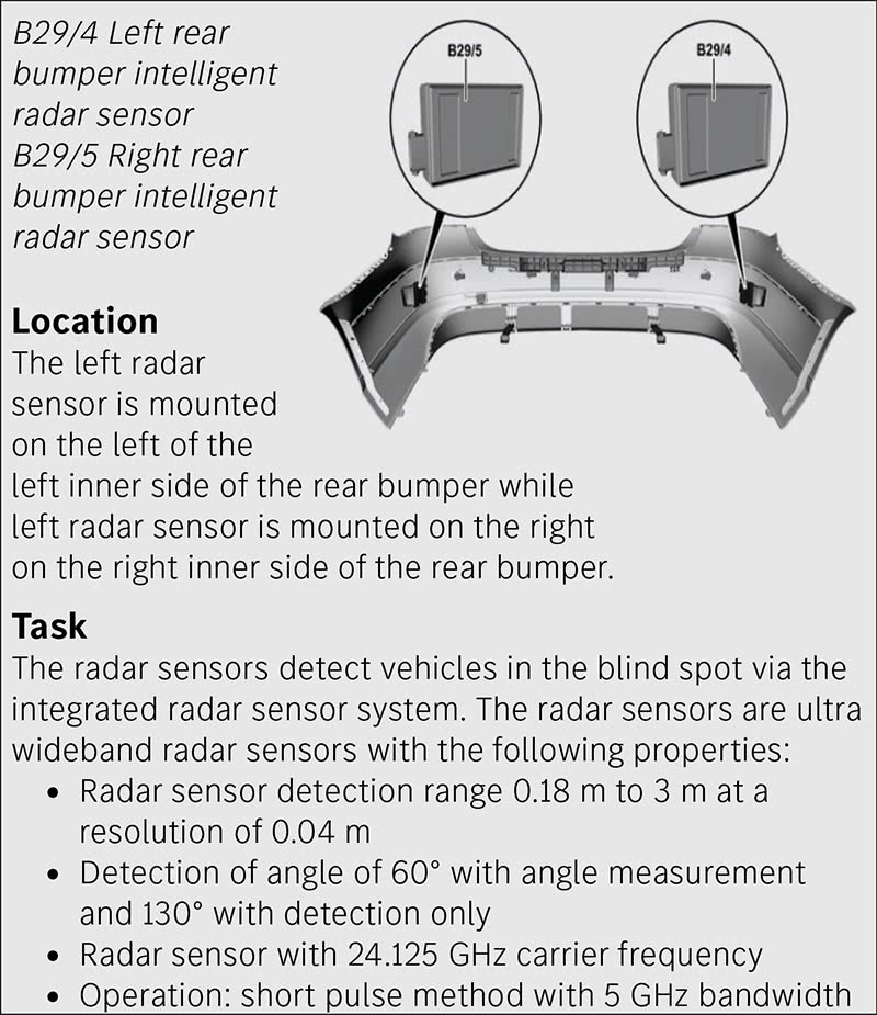
Radar Adaptive Cruise and ADAS Systems
Radar Adaptive Cruise Control radars use other allocated microwave ISM bands. Depending on the system version, radar adaptive cruise units and Intelligent Radar Sensing units can run in either the 24 GHz range (older versions) or the newer 76—81 GHz range. Detecting these very high frequencies is a challenge, so diagnosis really depends on XENTRY Diagnostics and the test routines it contains.
We’ve got wireless signals in Mercedes-Benz vehicles that span nearly the entire range from sound to light. Considering this, studying RF principles and learning how to capture, measure and verify its presence will become increasingly important going forward in effective diagnosis of Mercedes-Benz vehicles.
Author’s advice: A great way to study, grasp and practice in the RF realm is to look into becoming an amateur radio operator, or ham. Your author has been an FCC licensed Amateur Radio operator for several years now and, once you begin to study there, you will quickly come to realize (as I did) how much we don’t really know about electricity and electronics. Taking on a hobby such as this will give your automotive technical skills the biggest boost that could possibly be experienced, save an electrical engineering degree. Try it, you might like it and learn some cool new stuff along the way. Visit arrl.org to find a local radio club where you’ll be welcomed with open arms and whatever assistance you might need to get your own license. Free education that will help you make more money? What a deal!


0 Comments