by John Anello, “The Auto Tech on Wheels”
I was called in to a shop for a complaint on a 2004 Nissan Armada (Figure 1). The MIL (or CEL, if you prefer) was on, and there was a lack of throttle response. The shop pulled trouble codes from the PCM pertaining to the accelerator pedal sensor and decided to replace the accelerator sensor assembly. This was not a good decision on their part because the problem was still there to haunt them. Now that they had put a part in the car they couldn’t very well return it unfixed, so they had essentially married. There was no turning because if you decide to turn the job away without resolving the problem, you can’t expect the owner of the vehicle to pay for any parts used in the attempted repair. That would be a nasty automotive divorce that could empty your pockets, not to mention costing you a customer who would have to look elsewhere. At this point, the garage called me in to get a second opinion.
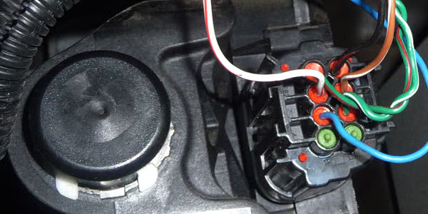
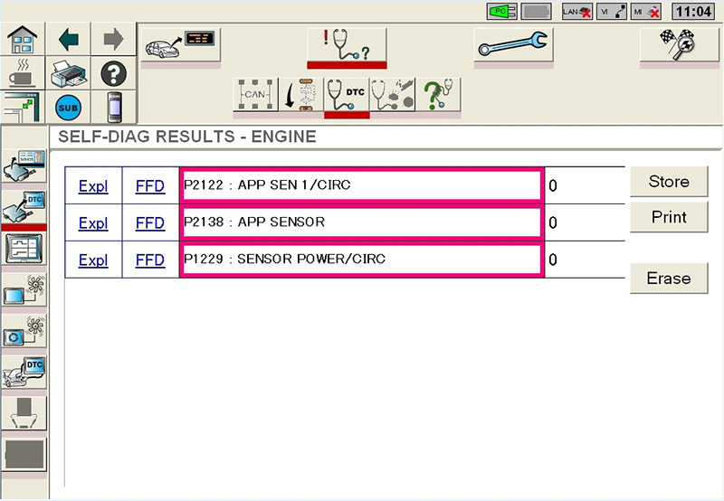
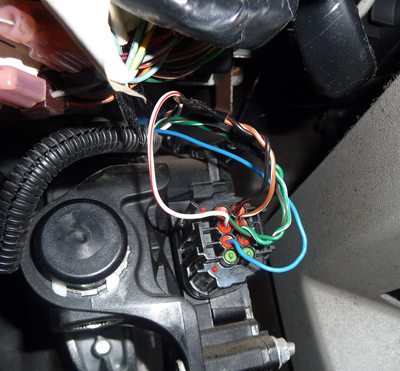
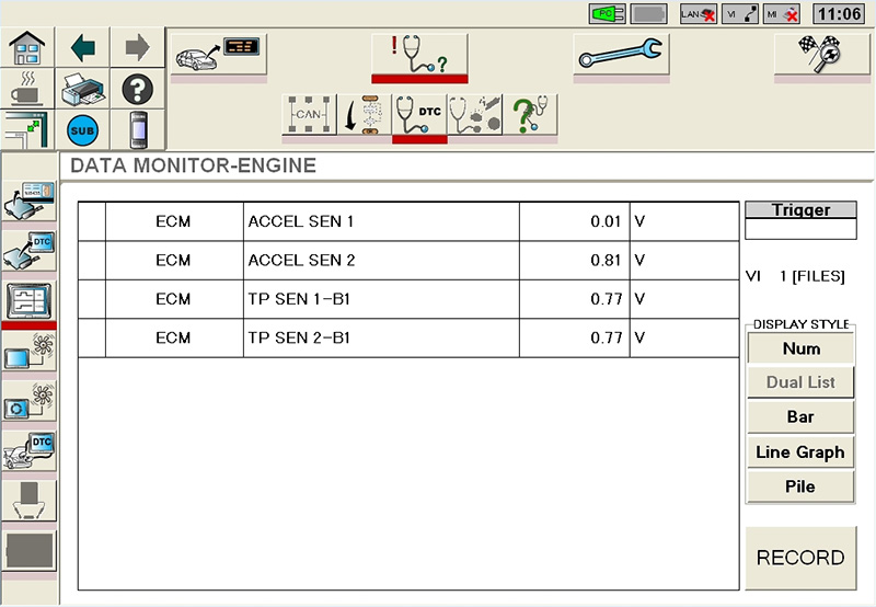
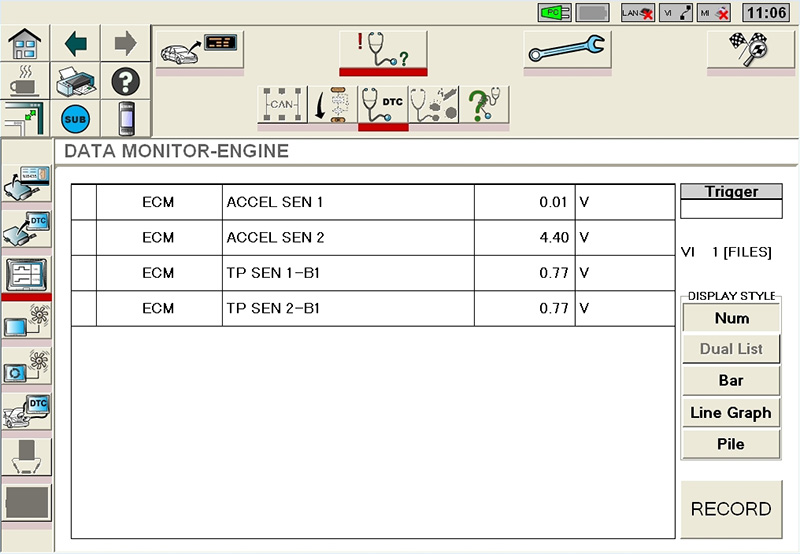
When I arrived, I attached my Nissan Consult III to the truck and pulled codes P2122, P2129 and P2138 (Figure 2), which were current. These codes dealt with the accelerator sensor that was located on the gas pedal. This is a dual potentiometer that provides the Powertrain Control Module with input on the position of the gas pedal. Both potentiometers are supplied with a separate five-volt reference and ground. The grounds are braided around each sensor signal line to cancel out noise (Figure 3). I used the scan tool to view both sensor signals at closed throttle with the key on/engine off (Figure 4) and noticed that accelerator sensor #1 was at 0.01 volts while accelerator sensor #2 was at 0.81 volts. Then I moved the accelerator pedal to the floor and accelerator sensor #2 displayed 4.40 volts while accelerator sensor #1 never changed (Figure 5).
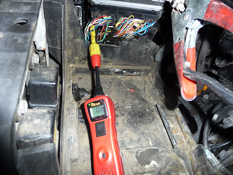
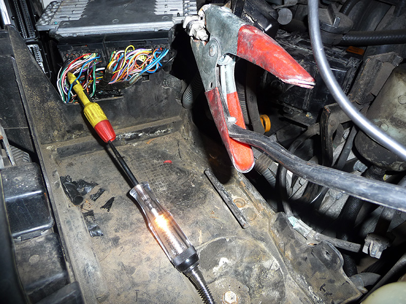
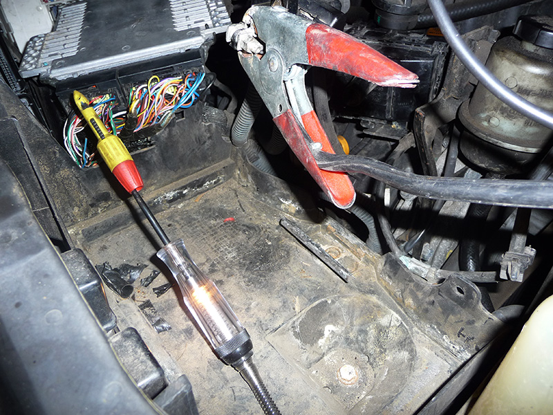
The only way accelerator sensor #1 could be low was if the sensor had an open or shorted five-volt reference feed from the PCM, or an open or shorted signal line going back to the PCM. At this point, I decided to get my Power Probe out to do some simple checks at the accelerator sensor. I checked both five-volt reference feeds at the accelerator sensor first and found 0.2 volts at sensor #1 (light blue wire). I had to prove this circuit out, so I went directly to the PCM connector. The reading at there was also 0.2 volts (Figure 6), but I wasn’t sure if this was a shorted circuit to ground, or a lack of five volts coming out of the PCM. To be certain, I placed my test light on sensor #1’s feed circuit while it was connected to the positive side of the battery and the test light lit up (Figure 7). Keep in mind never to use a test light on a good working reference voltage feed line because the high current draw of the test light bulb could damage the internal circuitry of the PCM. The line was already low, so there was no chance of creating any damage if it were shorted to ground or open within the PCM.
Now that I’d determined that the circuit was shorted to ground, I had to validate whether the short was internal or external to the PCM. So, I cut the wire at the PCM leading back to sensor #1 and found that the short circuit remained (Figure 8). This had to be a bad PCM because the short was now found to be on the PCM side. I advised the shop to get a used PCM just to keep costs low, and that I would be back to program it once they were able to locate one. I left feeling pretty good with my final diagnostic decision, so I moved on to the next shop.
Later in the week, the shop called in the morning asking me to program the used computer, so I went back there later in the day. I soldered the wire I had cut and paired the used PCM to the security system so the car would start. After it ran for a few seconds, the MIL came back on. This was not a good development because suddenly I was feeling the double marriage thing!
I switched my Nissan Consult III from security mode to scan tool mode and rechecked the codes. The same codes came back and I was no further along than when I had started. I now had to take a step back and rethink my game plan because now the shop and I were both married to this vehicle and we had to come up with a resolution. This was a case of automotive polygamy and this truck was not letting go of either one of us.
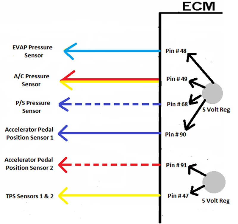
I knew from prior experience that the five-volt reference line can leave a PCM and feed multiple sensors, and if any one of those sensors shorted the line internally to its ref ground, or the line itself shorted to ground, then all the sensors associated with that line would suffer. I had isolated the independent accelerator sensor five-volt circuit from the PCM properly, the five-volt regulator feeding sensor #2 had a five-volt reference feed that seemed to be okay, and there were other independent five-volt ref feeds. Then I thought, “What if these independent feeds had a common regulator within the PCM and one of the five-volt ref feeds outside the PCM was shorted and back-feeding into the PCM?” I now had to view the entire PCM diagram and determine how many five-volt feeds were leaving the PCM and how many of those five-volt feeds were externally shorted. Then I could build a new diagram to show how the PCM feeds these sensors from a common five-volt regulator.
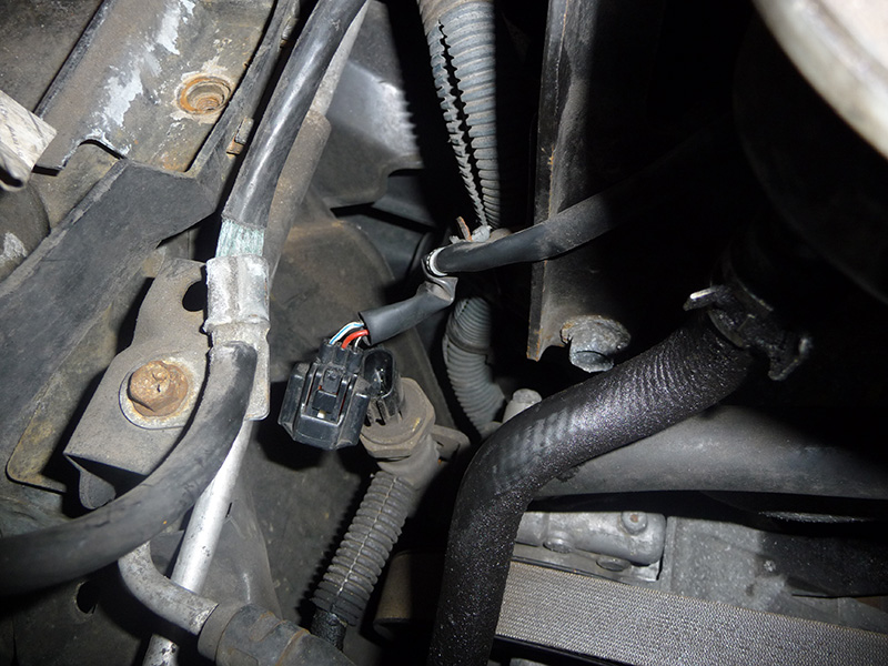
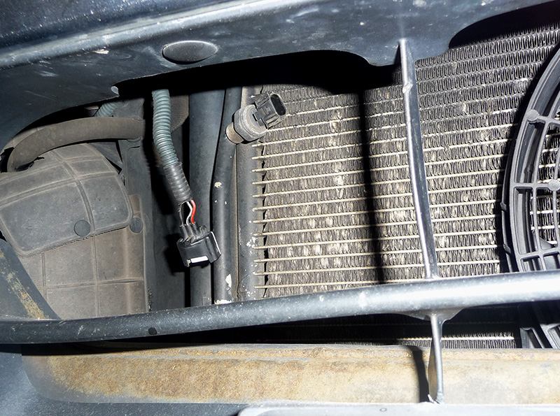
By testing the harness at the PCM, I discovered that accelerator sensor #2 and the TPS #1 and #2 reference voltage feeds were okay. The EVAP sensor, A/C pressure sensor, P/S pressure sensor, and accelerator sensor #1 circuits were all shorted with no five-volt reference feed. I now drew a new diagram to reflect my findings (Figure 9) so that it would help me better understand where I went wrong. I next decided to do an isolation procedure by unplugging all four sensors one at a time. If the short did not go away, I was dealing with a shorted circuit to ground leading to any one of these sensors. I first unplugged the accelerator sensor with no results, then I unplugged the P/S pressure sensor (Figure 10) and the short was still there. I next unplugged the A/C pressure sensor — no change (Figure 11).
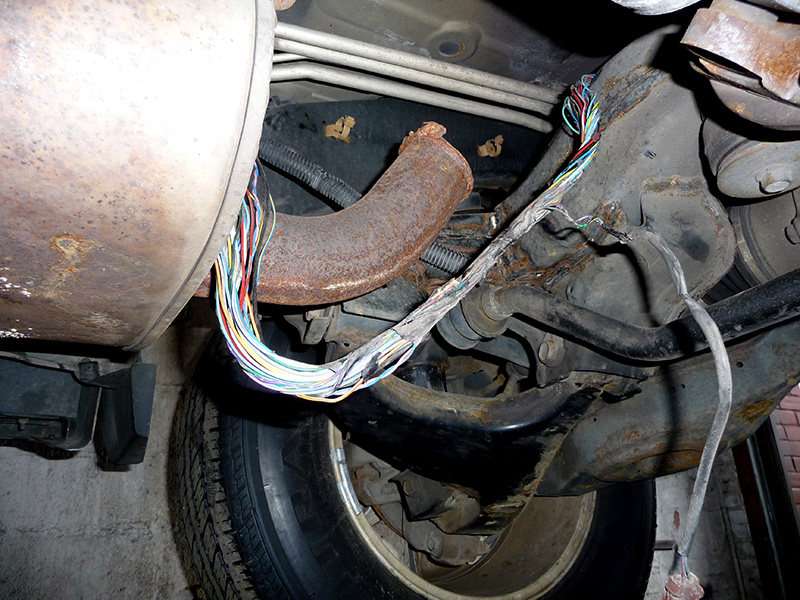
I now needed to get the vehicle up on the lift to access the EVAP sensor. As I was trying to locate the EVAP sensor in the right rear of the vehicle, I was suddenly taken aback by what I saw. The tail pipe had broken and the customer must have ripped it off the truck. This allowed hot exhaust gases to directly contact the main wiring harness that runs along the right side frame rail (Figure 12), melting it in such a fashion that the EVAP pressure sensor five-volt reference line was shorting to a ground wire.
What a turn of events and a final end to my short-lived marriage to this vehicle! It was something I never expected to see, or even thought could happen. This was real curve ball that gave me a run for my money. I just never knew that independently-fed five-volt reference lines could be joined within a PCM. I had thought there would be a five-volt regulator for each sensor. In the past, I have seen five-volt lines feed out of one terminal of a PCM and branching off to four sensors, so you knew they all shared the same five-volt regulator. This one was a learning experience for me, and I hope for you as well.


0 Comments