Â
by John Anello,
“The Auto Tech on Wheels”
I got a distress call from a shop for a complaint of a hard starting when hot with a 1990 Chevy Celebrity with 3.1L engine (Figure 1). The old engine would run great when first fired up cold and had plenty of power, but as it warmed up it started to hesitate and run erratically. If it was shut off hot, it would be very hard to restart. The shop had already replaced the fuel pump, TPS, MAP sensor, and the PCM, but nothing seemed to resolve the problem. At this point the shop decided to call me in for a second opinion.
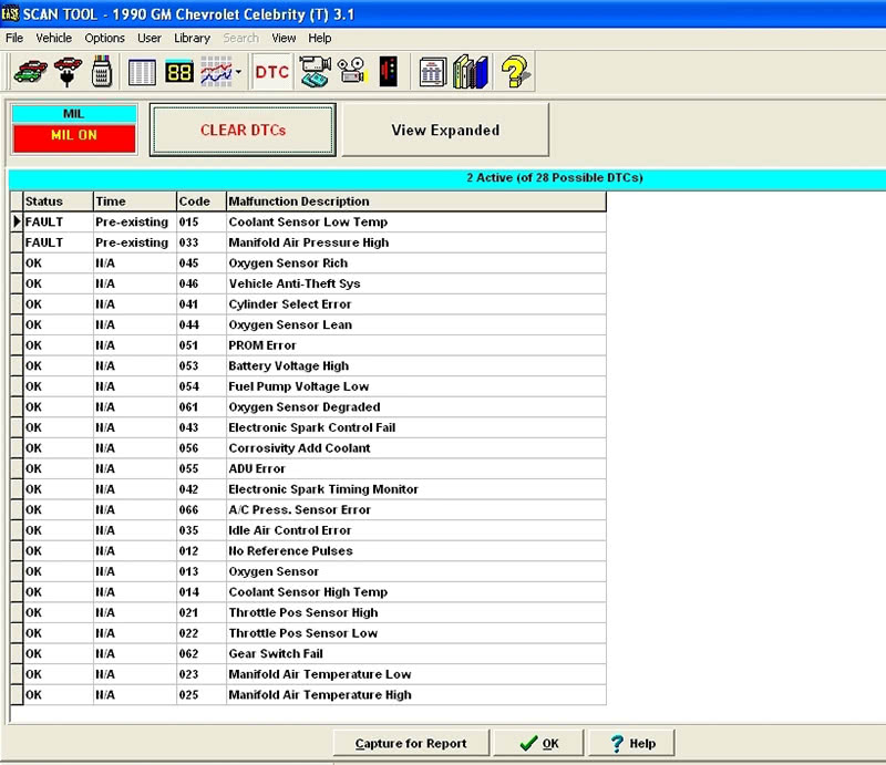
When I arrived, the engine was cold and it started up and ran with no problems present. I proceded to pull codes from the PCM and found a Code 15 (Coolant Sensor low) and a Code 33 (Manifold Air Pressure high) stored in memory (Figure 2). These codes were created by the shop when they were unplugging sensors to locate the cause of the problem. It is not uncommon to find codes in a system that are unrelated to the real problem — techs have created them during diagnosis. But it is still important to investigate them to validate if they were falsely set and then clear the codes to see if they return. The present codes must be cleared because there are certain controllers that may put the system in a default or back-up mode if they are not cleared from memory. Some systems may even place a default reading in the data parameter field dealing with a sensor error code that could throw you for a loop. It’s interesting that all this is relevant even on a 21-year-old car.
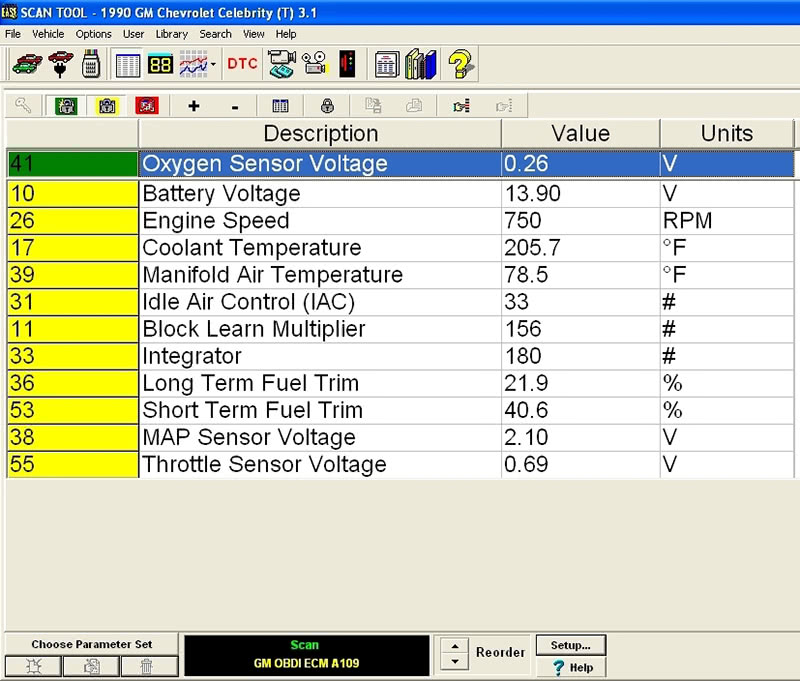
I proceded to view some main data parameters that would point me in a sensible direction. These consisted of RPM, Coolant Temp, Manifold Air Temp, Throttle Position, Manifold Air Pressure, Battery Volts, Block Learn and Intergrator. I watched these parameters as the vehicle was warming up. When the engine reached about 200 deg. F. it began to surge and run very erratically. The fuel adjustment ratcheted up to 156 Block Learn, 180 Intergrator, and the MAP reading increased to 2.10V due to loss of partial engine vacuum from the way the engine was running ( Figure 3). The Block Learn and Integrator was the old OBD I terminology for the OBD II Long-Term and Short-Term Fuel Trim. The value of 128 was used as the 0% neutral position of fuel trimming. As the values increased beyond 128, fuel was being added, and at any value below 128, fuel was being subtracted. But looking at numbers changing on a screen does an injustice when diagnosing a vehicle. The human mind is not great at number crunching and to get a better overview you really need to put these rapidly changing parameters into a graphing program.
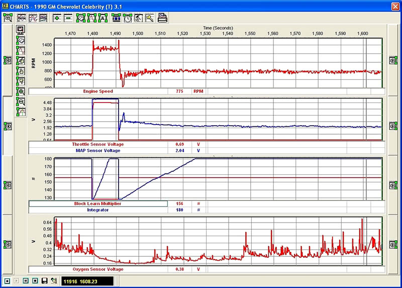
I set up my scan tool in a graphing format and placed four graphs on the screen (Figure 4). I chose to superimpose the TPS and MAP sensors on one graph, and the Block Learn and Integrator on another so I could see the visual relationships they held with one another. As I power-braked the engine in Drive near WOT (Wide Open Throttle), I could see how the MAP value leveled off close to five Volts indicating a loss of intake manifold vacuum. I could also see how the PCM went into open-loop fuel control by momentarily putting both the Block Learn and Integrator at a value of 128. When the the PCM saw that the O2 sensor was in a lean state, it immediately increased the Integrator value to near 180.
The main focus of the PCM is to achieve fuel control, and when it cannot meet its goal fine tuning the fuel requirements using the constantly moving Integrator, it will quickly kick in Block Learn to make a major adjustment in fuel delivery. When I released the throttle the PCM reverted to its stored Block Learn value of 155 and then started to add more fuel by moving the Integrator as high as 180 again. The O2 sensor still could not reach a threshold above 600 mV. This engine had a fuel starvation problem that the PCM could not overcome.
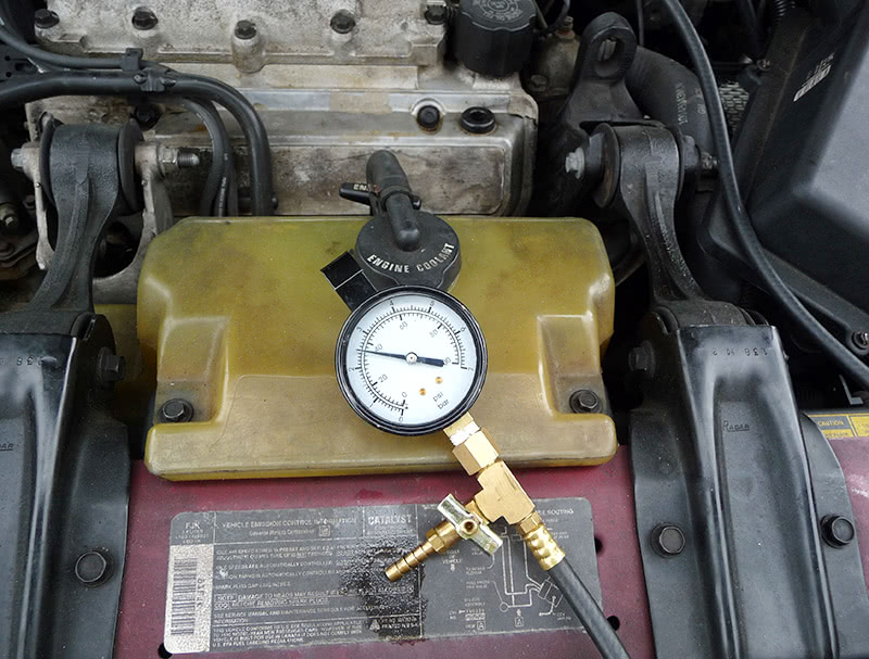
I kept it simple realizing that all the computer parameters were within their ranges. This had to be a fuel delivery issue such as low fuel pressure, or even clogged injectors. I next placed my fuel pressure guage on the engine (Figure 5) and saw that the fuel pressure was within specifications at about 36 psi, but I did not know if the PCM was doing its job of properly delivering the pulse width needed to keep the injectors open long enough for sufficient fuel delivery. Looking at a fuel pulse-width parameter on a scan tool is not a true indication of actual fuel delivery, but rather the pipe dream the PCM hopes to deliver if the injector driver is working properely. This could only be further diagnosed using an oscilloscope.
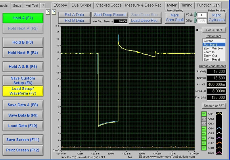
This PCM controlled the injectors using two separate drivers each managing two sets of three injectors each in group-firing format. I placed my scope leads on each injector driver circuit and viewed both voltage patterns in superimposed format on my scope screen (Figure 6). Both patterns seemed okay at first glance, but a closer look revealed that both injector patterns were elevated at about 3000mV and the PCM was unable to properly pull the injector field coil circuits fully to ground. This could be an indication of a poor PCM ground, a bad injector driver, or a shorted injector circuit. The voltage trace only gives you a portion of the picture and you really need a current waveform to see what’s going on.
Â
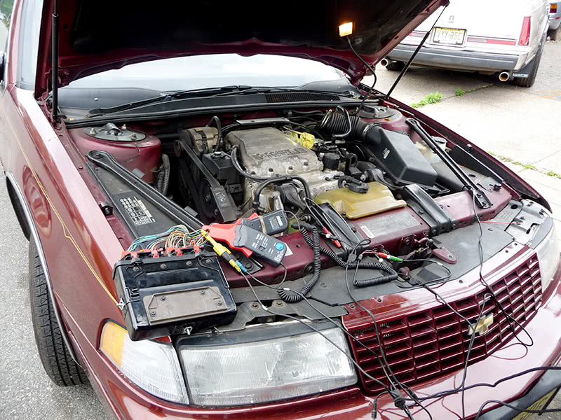
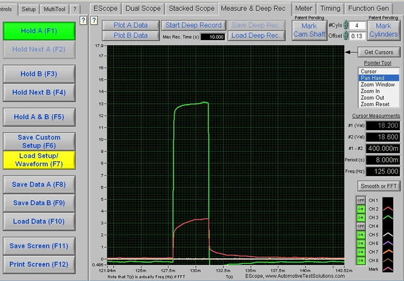
I next placed two current probes on the injector circuits so I could superimpose both injector patterns on one screen. This I did at the PCM, which was located at the right front engine compartment (Figure 7). As I was looking at the current waveforms of both injector banks, I immediately saw the problem that was creating the lean condition (Figure 8). One bank of injectors was pulling close to 13 amps, while the other bank pulled only about 3.5 Amps. These were high-impedance injectors, and normally required about 900 mA of current each, so one bank of injectors must have had at least one partially-shorted injector coil causing the PCM to limit both banks to a predetermined grounding threshold to control injector current. The end result was a lean fuel output.
This was an unforeseen problem that did not arise until the bad injector coil winding reached a certain operating temperature, which caused a domino effect taking down a whole injector driver circuit within the PCM. It was like a sleeping giant that was rudely awakened, and his only mission was to cause harm. There were no hostages to be taken, but only a mission of self-destruction. A scan tool can only be used as a window viewer to see what is going on within the PCM, but it may not necessarily provide you with the invasive testing you need that measuring equipment and scopes can perform. The key to any successful diagnosis is to build an arsenal of equipment that can take you to the next level. This is providing that you have the proper training to know how to use the equipment.
Â



0 Comments