


A look at some of the issues that develop in high mileage Volvos
850 and S70/V70 SERIES (1993-2000) DOOR STAY REPAIRS
“SNAP CRACKLE POP!â€
If you still see some of the good old 850 and early S70/ V70 series cars in your shop, you have probably opened a door or two to the sound of a loud crack or popping noise. In most cases the cause of the noise is damage to the part of the door sill that the door stay is bolted to.
Over time stress and metal fatigue take their toll on door sills and can crack. If you catch this problem in time it is relatively easy to repair, but if left unattended for too long the damage may become a larger issue that a body shop will have to attend to.
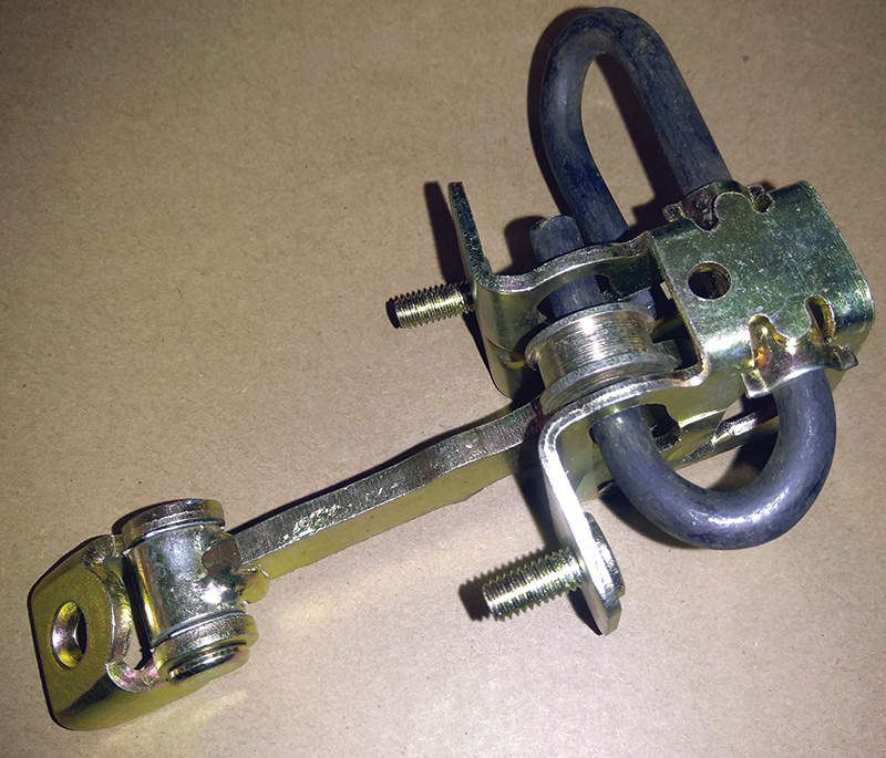
You should always replace the door stay mechanism with a new one at the same time you repair the cracked mounting area. It’s believed that a weak or worn door stay can lead to the cracks in the steel around the mounting bracket.
A lot of shops will just grind down the paint around the door stay mounting and mig weld the cracks. This method usually only lasts for a couple of years at best because the area is already weakened and needs to be reinforced. Volvo’s recommended repair procedure is to replace the mounting and weld the cracks around the door stay mounting.
You will have to start this repair by removing the affected door from the vehicle. Luckily on these early Volvos, the engineers had mercy on the technicians and made the removal of the entire door assembly VERY easy to do.
Volvo’s service bulletin (TP 32395/2) covers the repair of both front and rear door stay mounts, even though finding one of these Volvos that needs this repair in one of the rear doors is extremely rare.
Repairing loose door stops in A- and B-posts
This service bulletin [TP 32395/2, Section 8 (81, 84) Body and Glass; 850 1992-] describes how to repair damaged door stop welds.
Door stop mountings are available as replacement parts if a mounting needs replacing.
| Door stop mounting A-post is p/n 6817408-5. |
| Door stop mounting B-post is p/n 6817409-3. |
WARNING! The use of protective equipment such as safety goggles is recommended.
Procedures for preventing electronic component damage while arc welding:
- To avoid closed circuits remove the negative battery lead.
- To avoid ground potentials for different control units, place the welding ground lead as close as possible to the welding spot.
- If welding is to take place close to any control unit, you should remove the unit just to avoid the risk of heat damage.
Method, repairing door stop mounting in A-post
Preparations:
- Disconnect negative battery lead.
- Remove front door.
- Mask the A-post to protect it from welding and grinding damage.
- Protect the interior of the car with a fireproof cover.
- Cut a section corresponding to the section of the mounting still on the car, from the new mounting. Grind the mounting clean and even so that the new mounting can be welded into place.
Warning! The use of protective equipment such as safety goggles is recommended when welding. - Copy, cut out, and use the template in this service bulletin to ensure the correct alignment. Enlarge the image to actual size if possible.
- Hold the template against the A-post, below the position of the mounting. Align the mounting above the illustration on the template.
- Tack weld, check measurements, and adjust if necessary.
- Weld any cracks in the A-post.
- Steel brush and clean the surfaces to be sprayed. Sand with fine emery paper.
- Spray on primer, treat repaired, unpainted surfaces with rustproofing agent, apply color coat and varnish.
- Remove masking and protective cover.
- Reinstall front door.
- Check and if necessary adjust its function.
Repairing door stop mounting in B-post
Preparations:
- Move the front seat as far forward as it will go and cover it with a fireproof cover.
- Protect carpets and upholstery on the rear seat with a fireproof cover.
- Remove B-post panels.
- Disconnect battery negative lead.
- Disconnect connectors and remove wiring from the B-post.
- Remove rear door.
- Mask the B-post to protect it from welding and grinding damage.
- Mark the shaded section in the illustration using the template in this service bulletin. Enlarge the image to actual size
Shaded area of template
if possible. - Copy and cut out template.
- Cut out the marked section using an electric saw with a short blade.
- Stuff the hole in the B-post with a damp rag to protect against welding drops and residue. The rag should be large enough to be secured just under the round hole.
- Clean around the damaged weld on the door stop mounting.
- Use a rotary wire brush.
- Replace the door stop mounting if it is damaged.
- Use the template in this service bulletin. Position the template as illustrated. The door stop mounting should be above the marked section on the template. Enlarge the image to actual size if possible.
- Weld the door stop mounting.
- Seam weld the door stop mounting.
- Clean the weld and the surrounding area. Use a rotary wire brush.
- Remove the damp rag from the B-post.
- If necessary dry the damp area with compressed air.
- Check that the fireproof cover is protecting the floor and interior trim.
- Tack weld, align if necessary (use the template) and, when the panel section is correctly positioned, seam weld the entire joint.
- Grind the welds even.
- Take care not to damage interior trim.
- Re-spray repaired surface. Spray on primer, color coat and varnish. Dry with a heat lamp.
- See Service Manual Section 8 (80) for Paintwork Repairs
- Spray the repaired inside and outside of the B-post with rustproofing agent.
- Remove masking and protective cover.
- Reinstall wiring and panels.
- Reinstall rear door.
- Reconnect battery negative lead.
- Check door stop function and adjust if necessary.
When servicing these older Volvos it’s always a good idea to lubricate the door hinges with a spray lubricant. Your customer will notice if that old squeak is gone when they get in their car.
Valve body TF80-SC, 6 Speed Automatic Transmission
Vehicles affected: 2005- XC90 V8, 2006- S60R/V70R, 2007- XC90 3.2 & S80
There are a lot of Volvos and other makes of cars using the Asian Warner designed TF80 series transmissions on the road today. So whether you are working on a Volvo or any other make with one of these in it, knowing how to service and diagnose problems in the TF80 transmission will serve you well into the future.
A lot of these TF80 transmissions have had the valve body replaced already with an updated version as covered in Volvo technical journal TJ30547, but you will still get some of these Volvos in your shop with the original valve body or ones that are malfunctioning.
But don’t just throw a valve body at every Volvo that comes into your shop with a shifting problem, start with the basics.
When dealing with any Volvo with a transmission issue there are a few things you should check early in your diagnostics. Of course the first step is a thorough interview with the customer. Have the service writer get as much information as possible about the symptoms and, if possible, go on a test drive with the customer. Have them drive so you can see their driving style. How your customer drives the car can give you clues on where to start your testing. In many cases it can be difficult to replicate the symptoms if the car is not driven in a particular way.
If your shop has Volvo’s VIDA (and you should if you work on Volvos), after you check for stored data and codes, click on the Software tab and see if the customer’s car has the latest versions of the TCM and DEM software already installed.
Fluid condition is not easy to check as there is no dipstick on this transmission, but you can get a sample of the fluid by disconnecting the transmission cooling line on the top left of the radiator and pouring some fluid out into a clear container.
If you are going to change the fluid on one of these TF80 series transmissions you need to use the specific Volvo fluid type and follow the changing procedure outlined in Volvo TJ16673.
A word on changing transmission fluid on Volvos that have existing shifting problems. We all know the old story of shops changing the transmission fluid on weak transmissions and having the transmission fail shortly afterwards. But the real story is that the fluid is not the cause, the worn out transmission parts are the cause.
Many shops are protecting themselves by educating the customer and in some cases having the customer sign a waiver before they change the fluid.
Even if the codes are not in the TCM they could be related to the customer’s symptoms. Codes stored in other modules can give you clues on what’s going on in the transmission or maybe not in the transmission!
An example of this is described in Volvo’s TJ27713. If the Volvo you are working on has not had the DEM software updated it can cause vibrations and noises in the driveline in some cases.
After any transmission repairs it’s a good idea to try to re-learn the TCM. There should be no codes stored in the TCM or ECM, the transmission should be at operating temperature. Drive the vehicle at 20 – 25 percent throttle angle through all of the gears and then allow 20 – 40 seconds to slowly come to a stop so that the TCM can re-learn the coasting downshifts. The re-learn can take about 20 to 30 minutes on most Volvos with the TF80 Transmission.
Refer to TJ32546.2.0 for applicable TCM software upgrades for certain drivability complaints and/or DTCs. Not all drivability complaints and/or DTCs can be fixed by TCM software so VIDA should be used to properly fault trace DTCs. Other TJs can be used to remedy certain drivability complaints and/or DTCs. In the case that the complaint is not directly addressed by software and once the cause of the complaint is corrected, TCM and ECM software upgrades should then be attempted to be sure the ECM/TCM have the latest software.
SHIFTER BUTTON CRACKED — MOST VOLVO YEARS AND MODELS EQUIPPED WITH AUTOMATIC TRANSMISSIONS
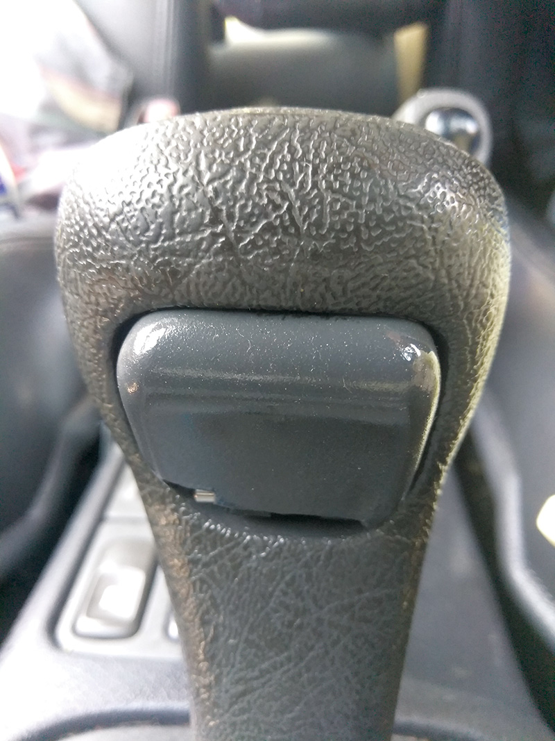
As Volvos age, some of the plastic components will become brittle and start to crack. In a lot of cases, this kind of wear is mostly cosmetic, but in the case of the plastic shifter button on Volvos with automatic transmissions, a cracked or broken shift button can turn into a problem.
If you are test driving a customer’s car and feel that the bottom of the shift release button is rough and jagged, you should recommended that the customer replaces the shifter knob assembly before it becomes a real problem.
What the customer will usually notice first in most cases, is that the shifter button starts to stick in, when the driver tries to shift into park and turn off the ignition.
If the shift release button is stuck in the release position, the cable that connects the shifter Interlock to the ignition lock cylinder will not allow the ignition lock to fully go to the (0) position and will not allow the customer to remove the key from the ignition.
Some customers can figure this out and pop out the sticking shifter button, but if the damaged shifter is not replaced it may become a safety issue over time.
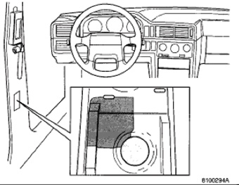
Replacement of the shift knob assembly on most of the affected Volvo models is relatively easy. To remove the old knob, start by applying the parking brake so the car won’t roll and turn the key to the first position so you can put the car in neutral. This is so the shifter is pointing straight up towards the roof of the car.
Now take a panel tool and loosen the boot at the bottom of the shift knob, grab the shift knob with both hands and pull straight up. This can take some force, so make sure you don’t hit yourself in the face when the shifter comes off the stalk.
To install the new shifter assembly you got from your local Volvo dealership parts department, just slip the new knob onto the shifter stalk and press down until it clicks into place. This can also take some force. If necessary you can use some shop towels to protect the top of the knob and tap it into place with a rubber mallet. Test the function of the new shifter and re-install the boot into the bottom of the shift knob.
Don’t let your customers find out the hard way about this problem!
Engine torque rod mount causing rattle and grinding sound from transmission area (XC90 2006- WITH SI6 3.2L SIX CYLINDER ENGINES)
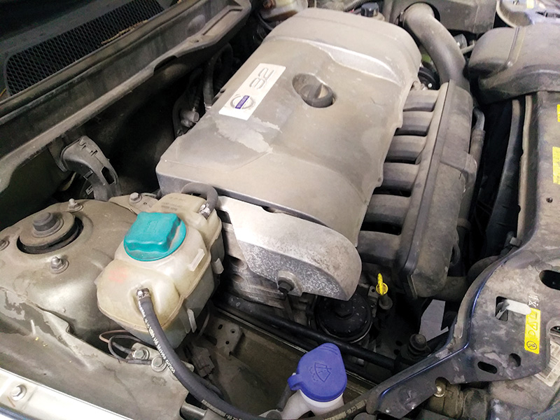
You may get one of these later XC90s in your shop equipped with the SI6 3.2L short six cylinder engine, with a customer complaint of an intermittent grinding or rattling noise coming from the engine area under light loads. The symptom usually happens more when the car is cold and can sound like there are rocks being ground up in the transmission or bevel gear.
It is difficult to replicate the noise if the car is on the rack with no load on the tires, so you will have to drive it until you observe the symptom.
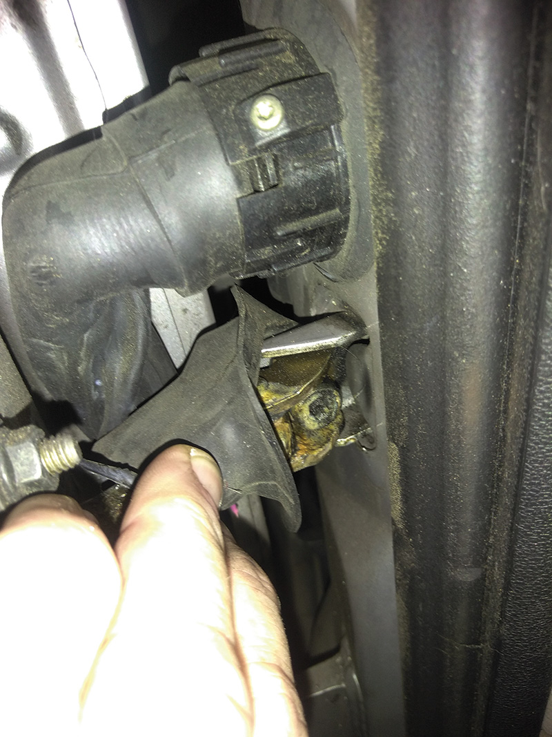
This sound is usually intermittent and can sound like the drivetrain is ready for the scrap pile, but before you break the bad news to the customer, you should remove the upper engine torque mount and test drive the car again.
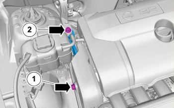
The torque mount is on the right side of the engine and is bolted to the right strut tower and the top of the engine block. Like most torque mounts this one has two rubber bushings to isolate engine vibrations from the body.
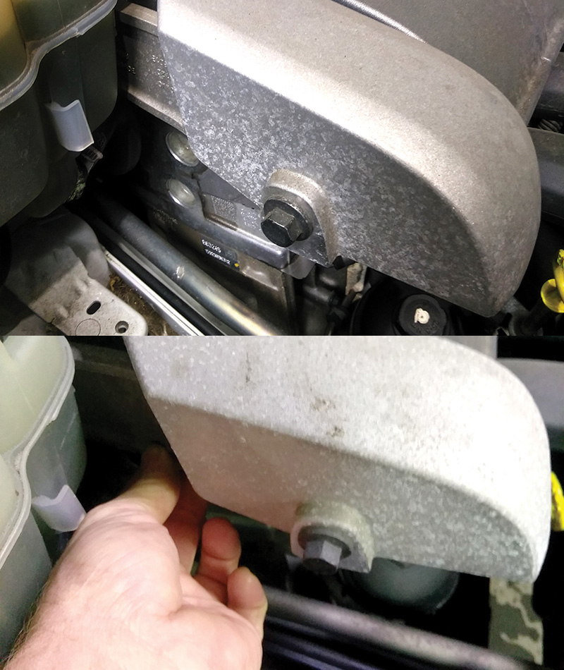
The bushing that is bolted to the engine is covered by a large cast aluminum cover so it’s difficult to see the condition of the bushings without removing the entire torque rod from the engine.
If the torque rod is worn out, it will rattle around when you grab it from the bottom to check for play. When you remove the torque mount you will usually see the front bushing is cracked and shrunken.
Several shops have mistakenly replaced transmissions and bevel gears to “fix†the noise that can be caused by this torque rod mount when it is worn out. So don’t jump to conclusions when you hear a grinding or rattle noise coming from the drivetrain on one of these Volvo XC90s that is equipped with the 3.2L SI 6 engine.
Download PDF


0 Comments