


This is not an easy job but it can be rewarding for both the technician and the customer.
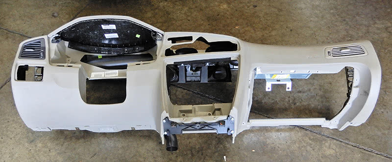
Replacing the air conditioning evaporator on a 2006 Volvo V70 is a huge job, needless to say. The complete dash and heater box will need to be removed from the vehicle.
You have a customer that comes in and says that the air conditioning is not working correctly, no cold air is coming out. The first thing to do is to see if the air conditioning compressor is engaging; if not, you will have to check to see if the system has refrigerant in it.
The best way is to hook up an air conditioning machine to the vehicle. Attach the high and low side hoses of the A/C machine to the high and low side connectors to the vehicle at the engine compartment.
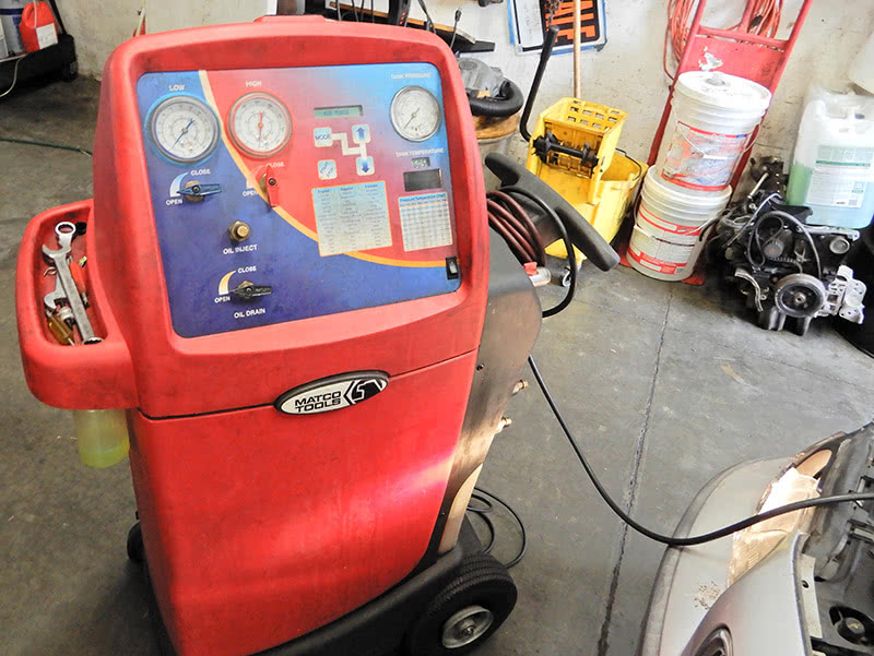
Once the hoses are connected, check the pressure. If the pressure is low and the A/C compressor is not coming on, the vehicle will need to be serviced. Recover all of the refrigerant in the system, and evacuate the system down to a vacuum. Once the system is evacuated, you can watch the gauge to see if the system stays at a constant vacuum; if the gauge raises, you’ll know that there is a leak in the system.
Add oil and dye into the system, and then add the right amount of refrigerant to the system. Start the vehicle to make sure the air conditioning compressor is engaging and the interior is cooling off. Test drive the vehicle to make sure the air conditioning is working sufficiently.
Now that the dye in the system and has circulated through it, you can now check for leaks in the system. After checking for leaks, you find that the evaporator inside the vehicle’s heater box is leaking and will need to be replaced.
The first thing to do is remove the refrigerant from the air conditioning system like before. Once the refrigerant is removed, drain the coolant from the engine completely.
Disconnect the heater hoses at the firewall.
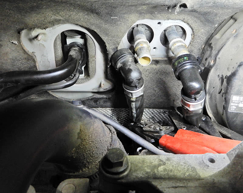
Remove the two bolts that hold the cover plate and rubber seal to the heater core. Remove the cover plate and seal.
Once the A/C refrigerant is recovered, right next to the heater hoses are the A/C hard lines going through the firewall to the expansion valve that need to be removed. Remove the two big wire nuts at the panel and remove the cover plate. Remove the center bolt that holds the lines to the evaporator, and pull the lines from the expansion valve.
Plug the hard lines at the A/C system so moisture or debris do not get into the lines. If possible, cap the lines at the heater core.
Remove the nuts at the wiper arms and remove the arms from the vehicle. Remove the four plastic rivets from the cowling. On each side at the A-pillar, remove the rubber fasteners from the cowling.
Once the rivets and rubber seal at the A-pillar are removed, remove the cowling from the vehicle. Remove the windshield wiper motor assembly, disconnect the electrical connector and the two bolts that hold the wiper assembly in place.
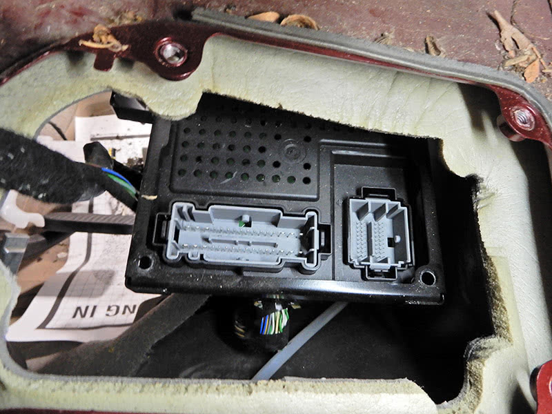
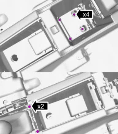
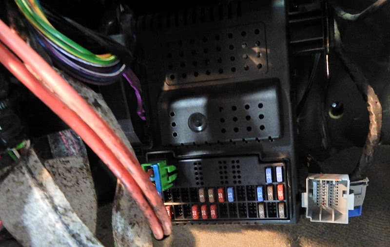
Move both front seats all the way to the rear and remove the battery negative terminal. Remove the four bolts from the cover over the Central Control Module (CEM) that are under the wiper assembly. Pull back on the cover and disconnect the two connectors at the CEM. Using a T25 torx socket, remove the two screws at the frame to the CEM; this will allow you to remove the CEM when it comes time to do so.
Now that the outside components are removed, move to the inside of the vehicle to remove the dash.
Remove both kick panels at the driver’s side and passenger’s side, remove the two side panels at the center console. Remove the A-pillar panel on both sides, pull out on the panel and lift upward, disconnect the safety clip.
Remove the panel at gear shift rod, use a trim tool to pop the trim up. Move the shift rod to the bottom position to give room to lift the panel. On the bottom of the panel, open the four catches at each corner and release the inner panel. Remove the two screws at the front of the center console. Open the center console compartment, pop out the panel at the bottom and remove the two screws.
Pull up on the emergency brake handle and remove the boot around the parking brake handle. At the back of the console, remove the ash tray or panel and disconnect the 12-volt power supply connector.
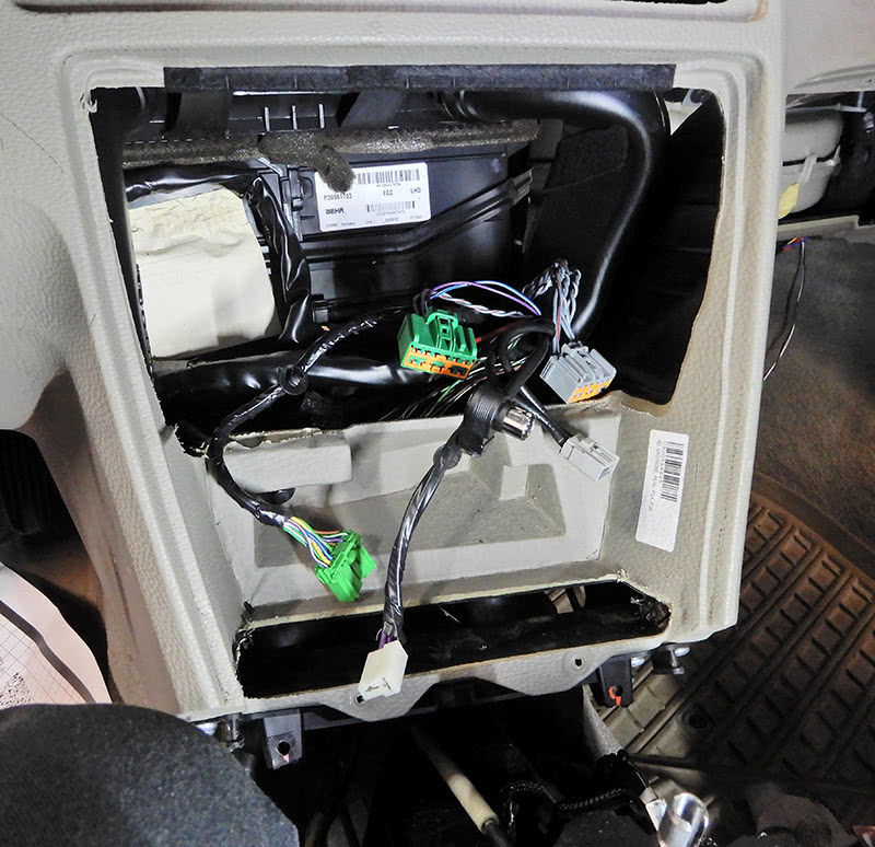
Lift up on the center console carefully, slide the console over the parking brake handle, and set the console aside. Remove the two screws at the bottom of the radio and climate control unit. Pull the complete unit out and down to remove. Disconnect the electrical connectors at the back of the radio and climate control unit. Remove the unit from the vehicle.
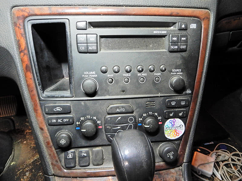
At the shifter controls, lift up on the cable connector for the gear lever lock; this will make it easy to slide the gear selector handle back and forth. Remove vent above radio assembly using a trim tool to release the catch, disconnect the hazard warning switch electrical connector. Lift up on the sun sensor at the top of dash, disconnect the connector, and remove the sensor.
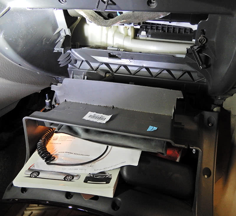
Remove the speaker at the top of the dash board and disconnect. Remove both end covers at the dash near the A-pillars. Open up the glove compartment and release the upper mount for the gas strut. Release the limiter stop. Remove the connector for the light, remove the screws that hold the glove compartment in place, and remove the glove compartment from the vehicle.
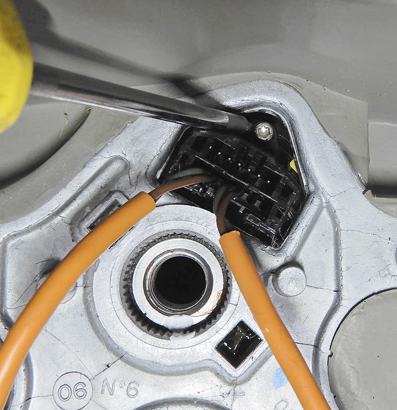
On the driver’s side, at the bottom of the dash, remove the two screws that hold the data link connector in place. Remove the air bag at the steering wheel. On cars equipped with a 3-spoke steering wheel, turn the steering wheel a quarter turn so the two holes at the back of the steering wheel are accessible. Insert a small screwdriver at each hole and lift up to release the air bag at the steering wheel. Note that on cars equipped with a 4-spoke steering wheel, there are two T30 Torx screws that hold the bag in place instead of the spring clips. Disconnect the electrical connector for the air bag and remove the air bag.
Center the steering wheel, using the screw that is inserted at the steering wheel secure contact reel. Remove the center bolt at the steering wheel; it would be a good idea to mark the steering wheel so that it can be reinstalled in the same position. Remove the steering wheel from the column. Feed the air bag connectors through the steering wheel.
Pop up the cowling at the top of the steering column. Remove the three screws from the cowling at the bottom of the steering column and remove the cowling. Remove two screws at the lever hub and disconnect the electrical connectors; remove the lever hub with the turn signal switch and wiper switch.
Remove the trim at the Driver Information Module (DIM), pull straight out. Remove the four screws at the DIM, unplug the electrical connector and remove the DIM from the vehicle.
Insert the key in the ignition and turn to the number two position and remove the cable from the switch to the gear lever. Remove the bolt at the bottom of the steering column that connects the steering rack. Remove the four bolts at the steering column and remove the column from the vehicle.
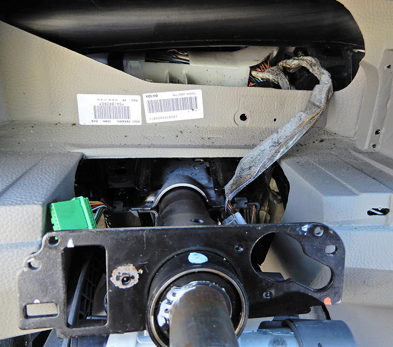
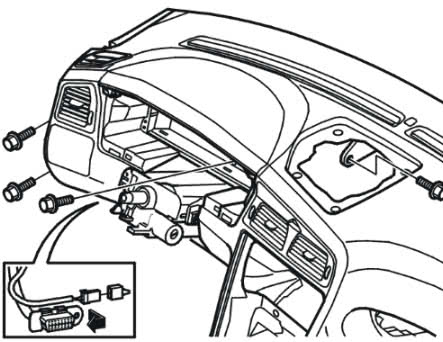
At the dash near the A-pillar on both sides, remove two bolts from the dash to the body of the vehicle. Remove the one bolt behind the DIM from the dash and the bolt at at top of the dash where the speaker goes. There are two bolts at the dash behind the radio assembly that need to come out. On the passenger’s side, remove two bolts behind the glove compartment near the air bag. Disconnect the air bag electrical connector.
Pull the dash out a bit to remove the brackets on both sides at the A-pillar for the electrical connectors. To remove the dash, pull straight out, move the gear selector handle backwards, maneuver the dash around the gear selector handle, and remove the dash from the vehicle.
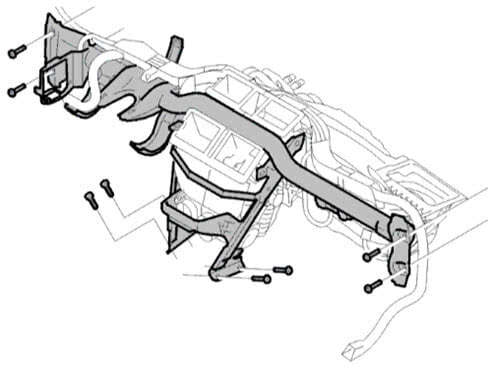
Now to remove the metal frame over the climate control box. Eight bolts hold this frame in place; remove the bolts. Disconnect the electrical harness at all connectors. Remove the tie wraps that hold the harness in place. Remove the air ducts from the climate control box.
Disconnect the harness at the center console area and maneuver it through the bracket near where the radio would be. Remove the bolts at the bracket and remove the bracket. Remove the other bolts that hold the metal frame to the climate control box. Disconnect the electrical connector at the blower motor.
Pull up on the electrical harness and remove the metal frame around the climate control box.
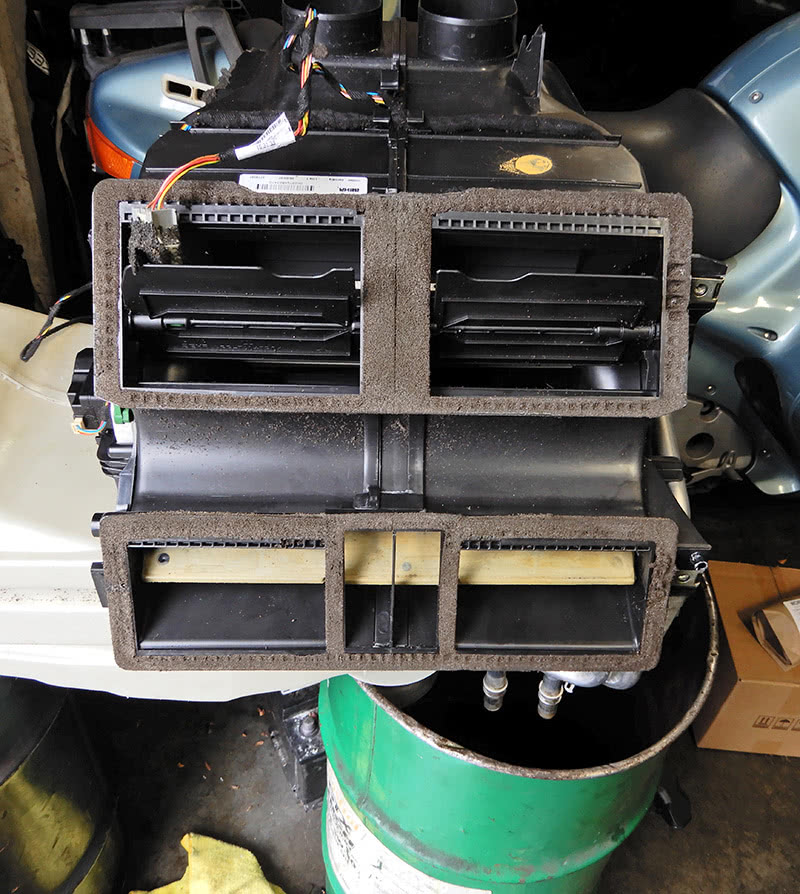
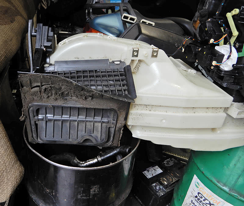
Now that the metal frame is removed, you can remove the climate control box from the vehicle. Set the climate control box on a bench so that you can remove the evaporator from the unit.
Remove the seals at the front of the climate control unit around the metal pipes, heater core pipes, and evaporator pipes. Remove the tie wrap at the heater pipes, remove the two screws that hold the heater core in place, and pull the heater core with pipes out of the climate control box.
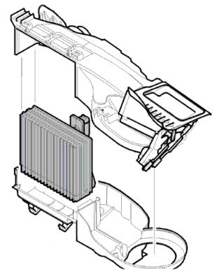
Remove the cabin filter and blower motor from the unit. Remove the three screws at the central electrical unit and remove from the climate control box. Using a screwdriver and pliers, unlatch the upper and lower sections of the climate control box.
Lift up and separate the lower and upper sections of the climate control unit, and remove the evaporator. Clean out the box with cleaner and blow dry. Using new o-rings, install the expansion valve to the evaporator. Be sure to lubricate the o-rings with compressor oil.
Set the new evaporator in place in the upper fan housing, making sure the seal sits in the correct groove at the expansion valve. Install the lower fan housing to the upper fan housing, making sure they line up correctly. Install the clips at the lower and upper fan housing and secure. Install the electrical unit to the climate control box with a new seal and tighten the three screws to secure the unit to the box. Install the heater core and pipes back into the climate control box and tighten down the screws. Add a tie strap around the pipes to the box.
Install the blower motor back into the climate control box. Replace the seal at the pipes, heater core and expansion valve. Replace the seal at the top of the recirculation flap.
Install a new cabin filter and screw on the cover. Now that the climate control box is back together, let’s install it in the vehicle. You might need to use two people to get it in place correctly. Once the unit is in the vehicle, connect the drain from the climate control box to the rubber hose that drains under the vehicle.
Install the metal frame over the climate control box, and start bolts at the A-pillar and tighten to 50 Nm. Install the bolts at the climate control box to the metal frame and tighten to 25 Nm.
Set the wire harness in place, route the harness through the metal bracket where the radio will go. Run the harness to the center console area and connect all electrical connectors. Connect the blower motor. Place the CEM back into place and connect all connectors.
Install the air ducts on both sides near the radio area. Set the fuse box back in place. Make sure the wire harness is completely connected to all components before installing the dash board. Route all remaining electrical connectors at the harness in their correct position.
Underneath the hood at the firewall, install the covers over the A/C expansion valve and heater core with pipes sticking out. Connect the A/C hard lines at the expansion valve and tighten. Connect the heater hoses to their correct position and lock down.
Insert the two screws at the bracket for the CEM and connect the electrical connectors at the top of the CEM. Install the top panel over the CEM and tighten. Install the windshield wiper motor and assembly. Install the cowling over the top of the wiper assembly, using new clips and secure. Install the windshield wiper arms and adjust.
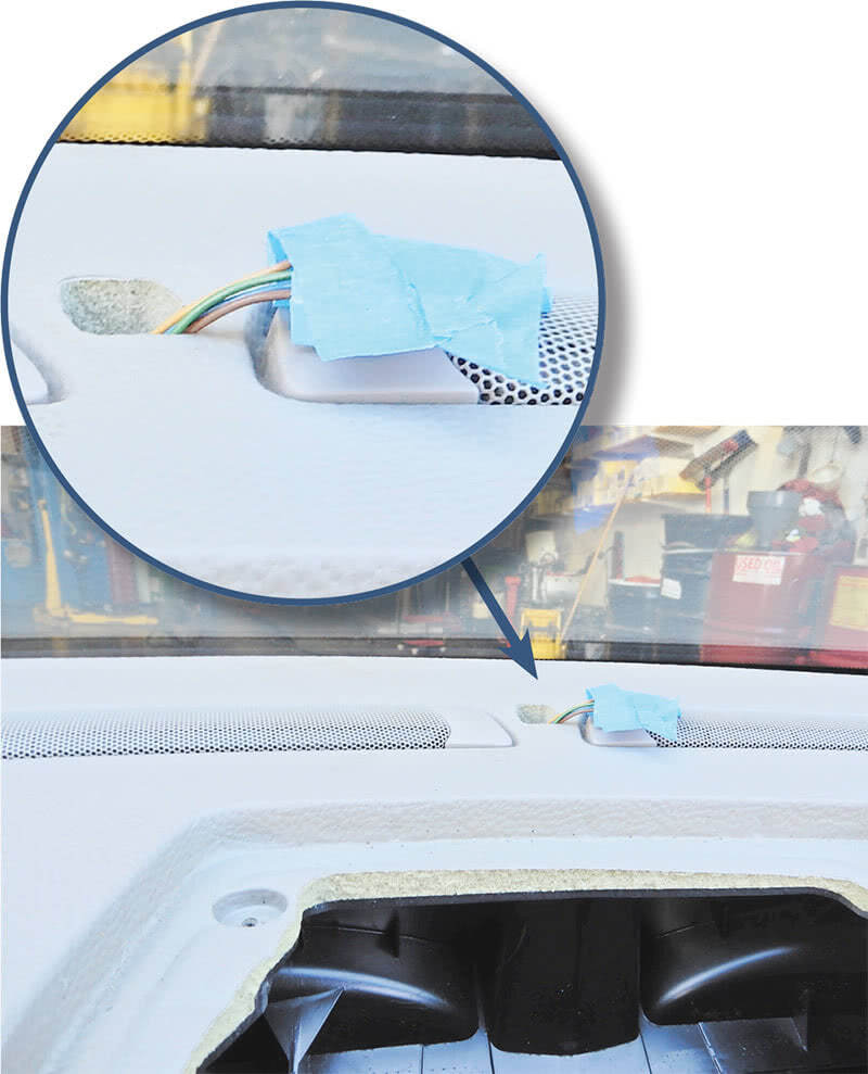
Now to install the dash pad. It is a good idea to use two people to set the dash back into place. When setting the dash in place, make sure to feed the wire harness for the sun sensor through the top of the dash. Once you have the dash in place, make sure all electrical connectors are where you need them to be.
Install the bolts at the dash to the A-pillar on both sides, install the two bolts near the glove compartment and connect the electrical connector for the passenger’s side air bag. Install the two bolts where the radio will go. Install the bolt at the DIM and at the top of the dash where the speaker goes. Tighten all these bolts.
Connect the sun sensor to the connector and push into place. Install the speaker at the top of the dash and and tighten down, install the cover over the top of the speaker. Insert all climate control vents. Attach the wire harness brackets at the A-pillar to dash.
Install the steering column, and connect the column to the steering rack and tighten. Install the shifter cable into the ignition switch assembly. Install the two screws to secure the data link connector under the dash on the driver’s left side.
Set the center console into place, connect the electrical connectors at the rear of the console for the 12 volt supply. Insert four screws to hold down the console, two in the front and two in the compartment. With the shifter in the back position, install the climate control module and infotainment system into place, connecting all electrical plugs.
Set the shifter cable into the correct position, leaving the shifter in the neutral position. Install the panel over the shifter selector with boot. Pop the shifter knob onto the shaft and push down until it is locked into position. Install the panel or ash tray at the back of the console. Insert the rubber mat in the storage compartment on the console. Slide the parking brake trim into place. Set the glove compartment into place and connect the electrical plug for the light. Install screws and tighten down. Connect the strut for the glove compartment.
Install the DIM into place, connect the connector and tighten down the four screws to hold into place. Insert the bezel around the DIM.
Install the steering wheel module, combination switches and clockspring, and tighten all down. Connect all electrical connectors. Install the trim at the bottom and top of the column. Install the steering wheel, feed the SRS harness through the wheel and tighten the bolt at the wheel. Install the air bag and connect, push into place.
Install the trim pieces on both sides of the console at the bottom area. Install both kick panels and connect the interior lights. Install the end covers at both sides of the dash.


0 Comments