

The Volvo automatic transmission has evolved through the years to provide a much smoother shift, a longer life, and a better ride.
Transmissions were developed in order to permit the gear ratio that exists between the vehicle engine and wheels to change when slowing down or speeding up. Gears have to be shifted in order to avoid not only overworking the engine but also to maintain it running at optimal rpm for performance.
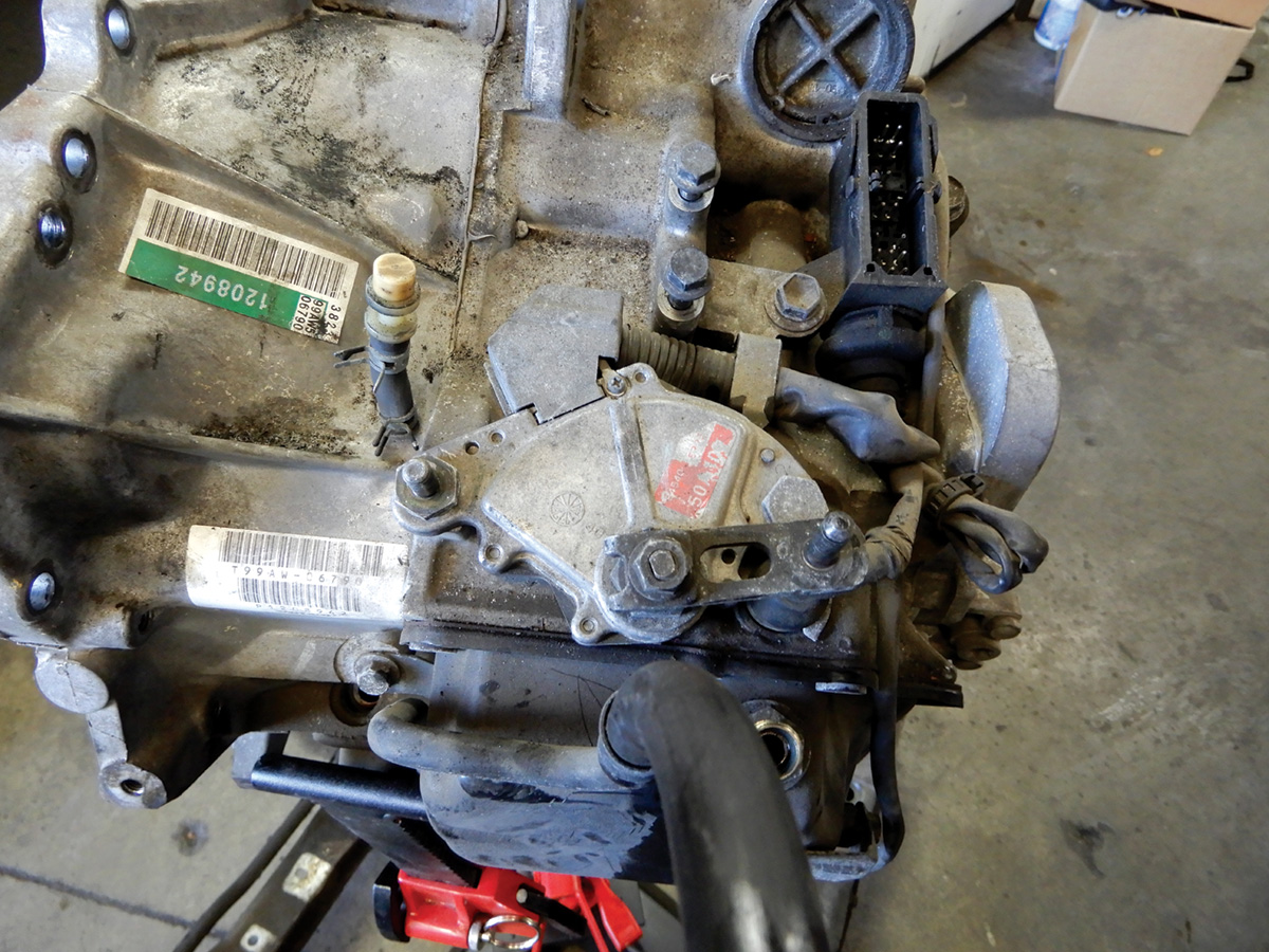
The 850 Volvo had a transmission that was developed for front wheel drive. It was used in 1993 to 1997 L5 2.3L and 2.4L applications, and is a four-speed, front-wheel drive transmission model 50-40 (AW50-40) Aisin Warner.
This transmission is a solid and reliable automatic transmission. It has just a few problems, but most problems are due to not maintaining them properly. Fluid needs to be changed every 20,000 miles.
To check the fluid, make sure the vehicle is level. Apply the parking brake and make sure the shifter is in the Park position. Start the engine and idle. With your foot on the brake, move through all positions from Park to Drive a couple of times, now back to Park. Wait a minute and check the fluid at the yellow dipstick. The level should be between Min and Max. If not, fill with genuine Volvo fluid.
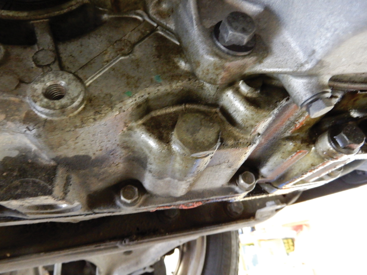
When changing fluid on these transmissions and the car is on the rack, remove the drain plug from the bottom side of the transmission. If the drain fluid is black or dark, recommend that the customer should change the fluid more frequently. Draining here doesn’t remove all the fluid. There is still some in the torque converter. Draining and filling the fluid a few times will get you back to clean red fluid. To fill fluid, use a funnel and fill at the transmission dipstick. Fluid should be checked while the engine is running and the transmission is in Park.
Replacing or adjusting the gear selector switch, or neutral safety switch. Volvo calls it a PNP switch.
Remove the air cleaner assembly from the vehicle. Also remove the battery and battery tray. Now that the switch is accessible, removing or adjusting will be less of a challenge.
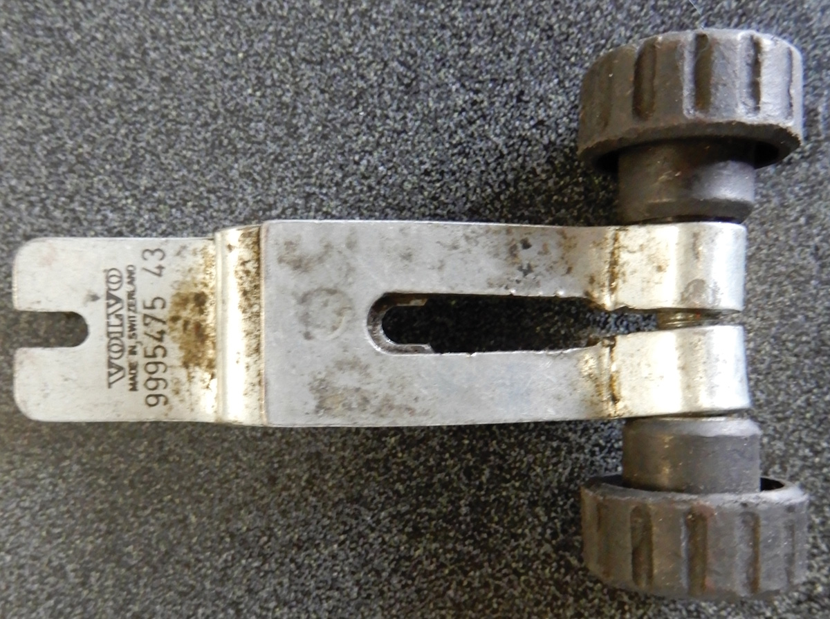
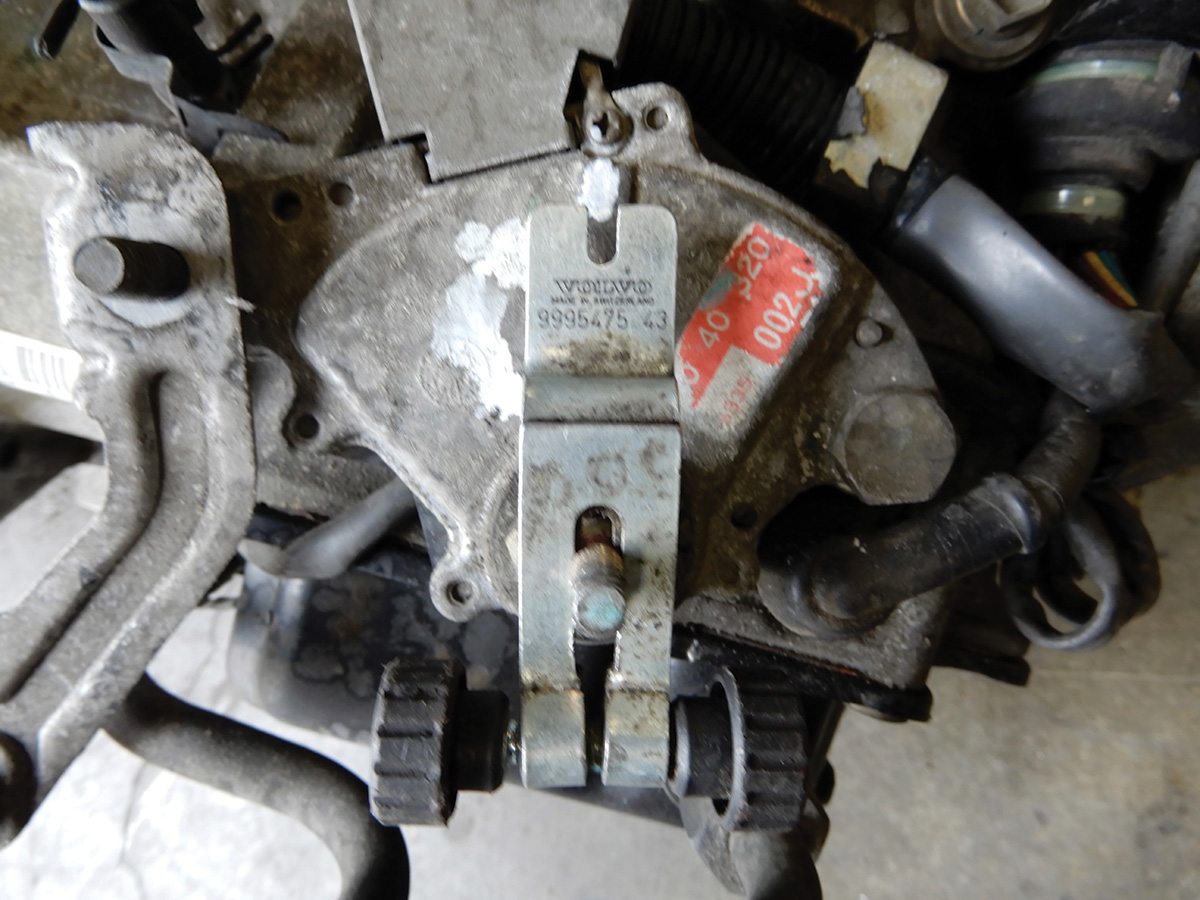
To remove the switch, remove the two bolts that secure the switch. Unplug and remove. Install the new one and leave the bolts loose for adjustment. Install tool number 9995475 at the linkage for the shifter cable.
Move the linkage until the tool has lined up the mark.
Once the tool is aligned, tighten and secure the bolts. Remove the tool and secure the linkage. Install the electrical connection, air filter box and the hose for the air mass meter. Make sure to check to assure that the vehicle starts in Park and Neutral and not in any other gear.
The 1998 to 2000 Volvo S70 and V70 used transmission AW55-50SN five speed, and the all wheel drive model was either the AW55-50 five speed or the AW50-42LE four speed.
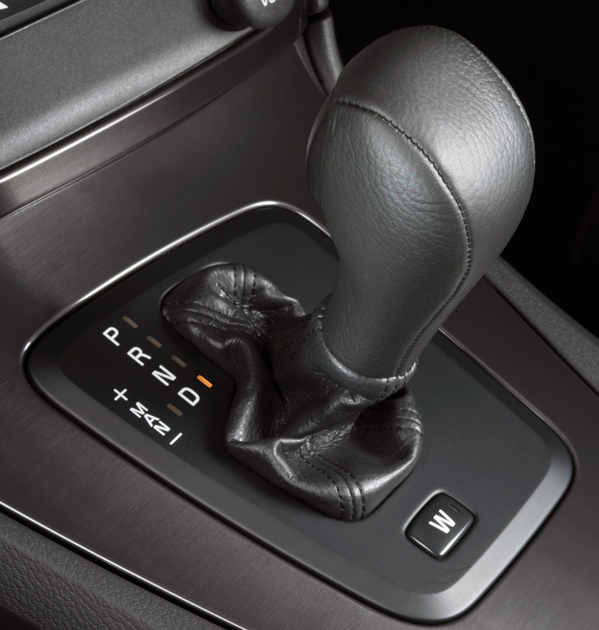
The 2001 Volvo used this same transmission, the AW 55-50 and the AW55-50SN, with a new feature. These five speed transmissions came standard with a Geartronic transmission, meaning you could shift the vehicle manually if desired. By pulling the shifter back to first gear and slightly pushing the shifter forward, you could shift through the gears. The position or gear will show on the instrument cluster.
The Geartronic transmission is a specific transmission brand that is commonly found in Volvo vehicles. It was designed to provide performance and flexibility. Geartronic has manufactured both a five-speed and a six-speed transmission for Volvo.
To replace the transmission in a 2002 Volvo XC70 you will need these tools:
| Volvo part number | ||
| 9985972 | 9995460 | 9995463 |
| 9995681 | 9995716 | 9995972 |
| 9995562 | 9997076 | 9997077 |
Disconnect the battery negative cable. The battery is in the rear of the vehicle. Now that the battery is disconnected, remove the air filter housing and fresh air intake hose. Remove the top torque rod which is attached between both strut towers.
Use tool 9997077 to remove the gear selector cable. Remove the bracket for the cable and set it aside. Disconnect both hoses going to the radiator. Drain the coolant and remove the bottom radiator hose. This will give room to get to the transmission-to-engine bolts. Disconnect the bracket for the oxygen sensor and move it out of the way.
Remove the two bolts from the starter and the other three bolts that hold the transmission to the engine. Disconnect the hoses at the firewall that lead to the heater core. This will help when lowering the engine. The quick connect hose release needs to turn counterclockwise and pull directly out of the coolant pipe.
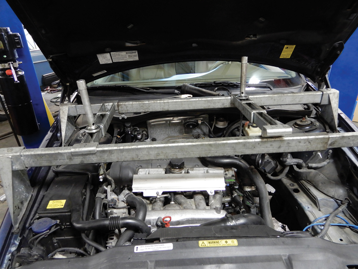
Install tools 9995716 and 9995460 and tighten so no tension is allowed.
Raise the vehicle on the hoist and remove the front tires, splash shield and air baffle.
On the front of the cross member remove the screws that hold the negative battery cable and the screw that holds the wire loom near the air conditioning compressor.
Remove both cross member brackets near the exhaust, along with the front bracket disconnect clips that hold the brake lines. Try not to bend them much. Remove the bolt from the steering gear at the knuckle and separate the gear from the shaft. Remove both engine mount bolts at the cross member. Remove the torque rod mount from the transmission to cross member.
Remove the outer tie rod nuts and separate on both sides. Remove the lower sway bar link nut and let the bar hang. Remove the ABS sensor from both front hub assemblies. The outside axle bolts need to be removed, along with the ball joint bottom nuts. Use tool 9997076 to pull down the control arm and release it from ball joint on both sides.
Remove two nuts on each side of the inner fender, bend it over out of the way and secure. Now that the control arms are separated from the ball joints this should give enough room to remove the axles from the vehicle. Next remove the right front axle bearing cap. Now the axle should pull directly out. On the left side use tool 9995681 to pry out the axle from the transmission.
The driveshaft will need to be removed. Mark both ends of the shaft so it can be put back in the same position, remove the bolts and center support and set the driveshaft aside.
Under the subframe on the left side, position a jack to support the frame. Remove the subframe bolts from the left side. Now lower the frame, making sure all hoses and cables are not getting stretched too far. Remove the jack and let the subframe hang.
Time now to remove the angle gear. Remove the five bolts connecting the angle gear to the transmission. The angle gear should now be removed and set aside. This is also a good time to repair any leaks at the angle gear and change the fluid. Remove three bolts and remove the bracket and engine mount near the firewall.
The torque converter bolts can be removed now. Turn the crankshaft so that each bolt head is visible and remove with a Torx T50 tool. Spin the crankshaft around until all bolts are removed. Drain the transmission of fluid and re-install the plug.
Lower the vehicle and lower the transmission by turning the left lifting hook until you can see the stop point, or until the transmission is clear of the body. Raise the vehicle back up and remove the rest of the bolts holding the transmission in. Leave one bolt in until the transmission jack and head fixture are in place. Set the head fixture onto the transmission jack. Lift the jack until the fixture aligns with the transmission and tighten the head fixture tool 9995463 to the transmission.
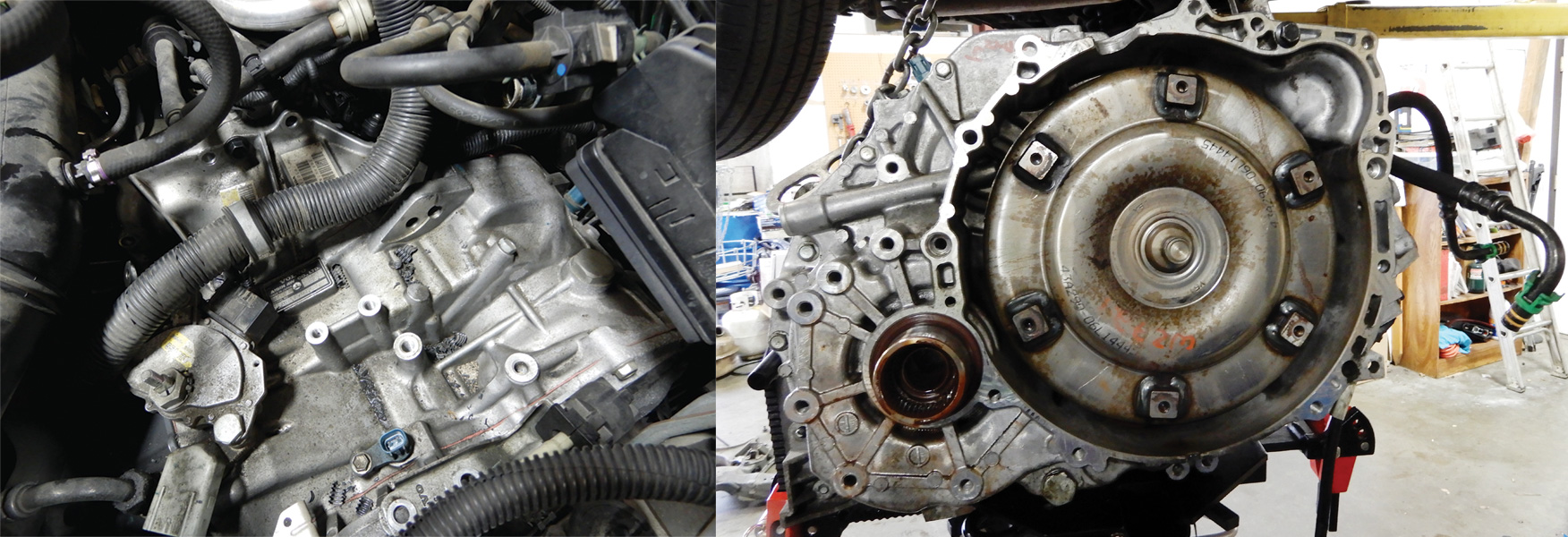
Removing the left control arm will give room for the jack head to slip around the subframe. Remove the last bolt and pull the transmission out, making sure to keep it even with the engine. Push the torque converter, with a screwdriver, back away from the flywheel. Lower the jack and make sure nothing is in the way and everything is disconnected.
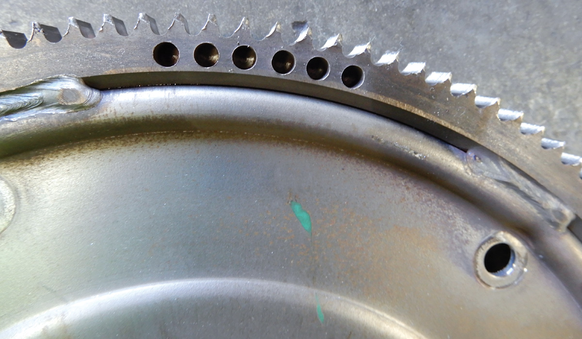
Before installing the transmission be sure to check to assure that the flywheel teeth are not ground down at all. If so replace the flywheel. Replace the rear main seal after the flywheel is removed. Install the transmission in reverse order. Let’s go over this order.
Secure the transmission to the jack. Try to line up the torque converter with the holes at the flywheel, this will make it easier to insert the bolts and tighten. Be careful not to break the speed sensor fitting.
Secure the transmission to the engine making sure they fit together evenly; adjust the height and angle with a transmission jack. Install a bolt or two just to keep everything in place. Use a small screwdriver to line up the torque converter holes. Tighten all bolts on the bottom that hold the transmission to the engine. Install the bolts for the torque converter and tighten. Spin the engine around a couple of times to make sure all torque converter bolts are in and tight. Secure the rest of the transmission bolts on the bottom.
Remove the transmission jack and head fixture. Lower the vehicle and lift the engine and transmission so that they are level. Raise the vehicle back up on the lift. Install the engine mount bracket and mount next to the firewall.
When installing the angle gear make sure the spline joint is clean of debris and greased before installing. Insert all bolts and tighten. Secure the drive shaft to the angle gear and tighten the bolts. Secure the negative battery cable.
Install a new rubber o-ring at the transmission cooler line at the bottom of the transmission.
The right axle can now be installed, making sure to clean and lubricate both ends of the axle, and assuring that the seal is in place at the front hub assembly. Secure the bearing cap and fit the bolt at the bearing hub and tighten. Install the left side axle and secure.
Fit a jack under the subframe on the left side and raise into position. Install the subframe bolts and leave loose. Secure the wire harness screw at right front, along with the bracket for the negative battery cable at the front of the subframe. Secure the steering rack to the steering column and tighten the bolt. Tighten all bolts for the subframe.
Install the bracket at the exhaust, making sure to secure the brake lines in position so they don’t rub against anything. Install the torque rod mount. Install the left control arm and tighten; pull down with tool number 9997076 and fit into the ball joint and tighten. Tighten the sway bar links both sides. Tighten down the tie rod-to-hub assembly.
Lower the vehicle and remove the lifting beams and hooks from engine, and tighten the bolts for the transmission and starter. Secure the shifter cable onto the bracket and transmission. Install the radiator hose and small bracket for the oxygen sensor. Fit heater hoses to pipes with quick connects.
Fit the air cleaner box into place and secure. Secure the hose to the air mass meter and tighten the clamp. Attach the electrical connector to the air mass meter. Install the air charge pipe to the turbo across the engine and tighten clamps. Install the upper torque rod between the strut towers and tighten.
Add coolant and top off. Fill the transmission with fluid, three quarts. Start the vehicle and let warm up to operating temperature. With your foot on the brake pedal, run the transmission through the gear selection, then back into Park. Re-check the fluid level and adjust as needed.
Raise the vehicle back up and check to make sure everything is tight and secure. Install the air guide and splash pan. Tighten the wheels and test drive the vehicle. Check the transmission fluid level again just to make sure the fluid is full.
Valve Body Inside Transmission
The AW55-50SN transmission is controlled by a computer and actuated by hydraulics. Replacing the valve body can eliminate hydraulic problems in this transmission.
Customers may describe shifting problems such as harsh engagement after prolonged coasting and occasional awkward shifts between 3rd and 4th gear. Having VIDA diagnose transmission problems while activating components can be a real help. Reading codes setting counters for fluid change and resetting adaption is needed after any work to the valve body.
Shift solenoids can sometimes be a problem in this transmission. Having VIDA hooked up to the vehicle and the key in number two position, activate the solenoids and you will be able to hear them click if they are working correctly. If no click is heard, replacing the solenoid will be necessary.
To remove the valve body or replace a solenoid, lowering the transmission to gain access to the valve body cover is necessary. Volvo special tools 9995716, 9995460, and 9995477 are needed to lift and lower the engine. After disconnecting the battery negative cable, put the engine lift bars and threaded hooks across the top of the engine and secure. Raise the vehicle and drain the fluid. Remove the front air duct. Add a new seal ring to the drain plug and tighten. Lower the vehicle and remove the air cleaner housing, disconnect the air mass meter plug and clamp holding the hose to the air mass meter. Pop up the air cleaner box from the three plastic clips that hold the box in.
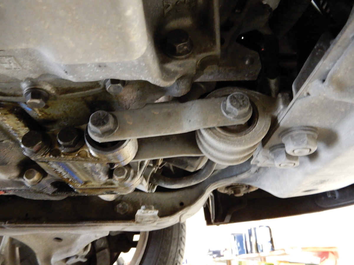
Disconnect the top transmission line at the transmission and at the radiator. Using a 22 mm crow’s foot flare wrench works well for this job. Put the special Volvo lift tools across the top of the engine. Secure the threaded hooks to the engine and tighten until no play is left. Raise the vehicle back up and remove the bottom transmission cooler line. Be sure to catch escaping fluid at the bottom of the transmission. Remove the bolt on the bottom for the front engine mount. Remove the torque rod mount.
Remove the front left subframe bolt. Disconnect the negative cable bracket and cable from the transmission. Remove the screw at the harness on right front. Loosen the front right subframe bolt but leave a few threads engaged. Loosen the rear subframe bolt on the left side two to four turns without removing the bolt. Use a spacer of some sort to put between the subframe and the body of vehicle at the front left. This will give room to get to the transmission pan. Remove the dipstick tube.
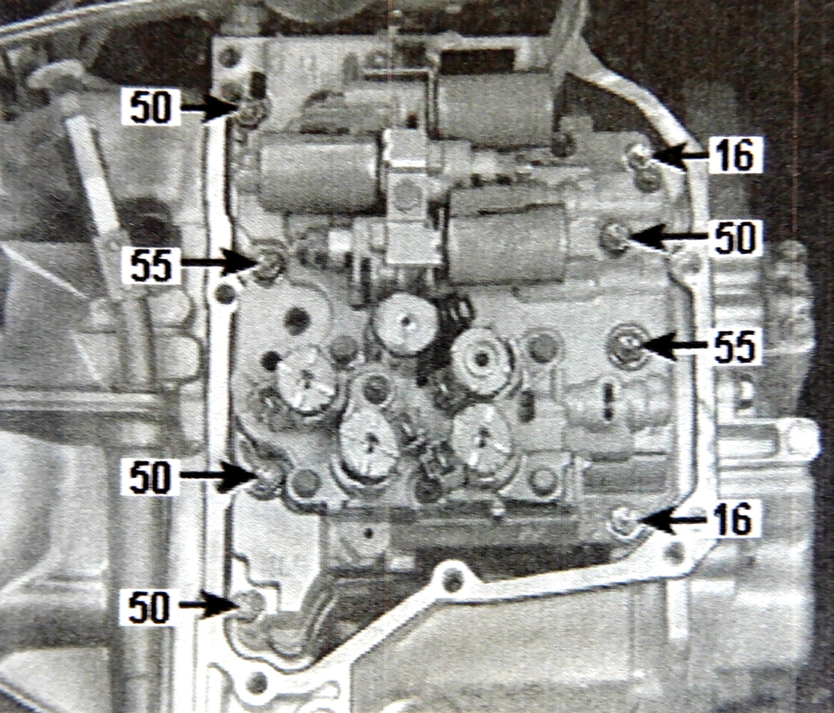
Clean the area around transmission pan so that dirt and debris do not get inside the transmission. Remove the nine bolts, Torx T40, from pan and remove the pan. Now the valve body will be exposed.
To check all solenoids, disconnect all of them and check resistance with a multimeter between the pins at the solenoids.
- Solenoid S1: Correct value 12-16 ohms.
- Solenoids S2-S5: Correct value 11-15 ohms.
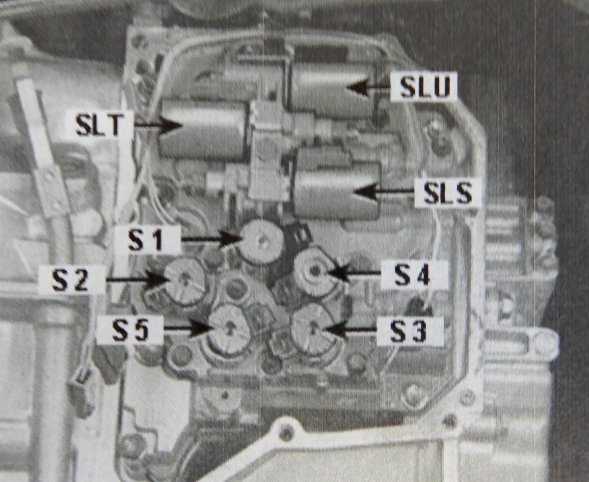
If any of these solenoids are out of range, replace them.
Correct value is 5.0-5.6 ohms.
If these solenoids are bad, replace control system.
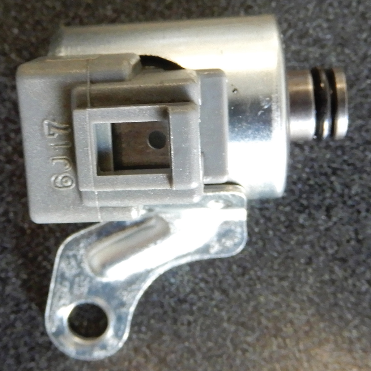
When replacing a solenoid, remove the screw and pull out. Lubricate the new solenoid seal with transmission fluid and insert and tighten screw to 7 Nm.
If replacing the control system, make sure the valve body and all connectors are disconnected and push the harness to the side out of the way. Remove eight screws from the control system and remove from the transmission. These screws are different in length, so be sure to note. After the unit is removed, replace two seals in the transmission and clean all debris. Hold seals in with grease.
Check gear selector slider, making sure it’s correctly positioned. Position the control system with new gasket in place, making sure that the lever for the gear selector is in Neutral. Install screws and tighten to 10 Nm. Connect the harness to all solenoids and secure the oil temperature sensor and connect.
Clean the pan surface and make sure it is flat. Use a thin layer of sealing compound and re-install to the transmission. Tighten all screws to the pan and reassemble the vehicle in reverse order. Make sure to replace the subframe bolts and tighten and reconnect the battery negative cable.
Add three quarts of transmission oil and start the vehicle. Run until the temperature is warm, check fluid again and top off and test drive the vehicle. After your test drive check again and make sure there are no leaks.
Install the air guide and splash pan.
Download PDF


0 Comments