


Vehicle computer communications and wiring systems have grown more complex. Understanding these systems may help you in your next wiring diagnosis.
Through the years, Volvo vehicles have changed not only in appearance and capabilities but also with the vehicles’ computer communication and the wiring system.
Electrical circuits have become more complex with the addition and interconnection of various systems in Volvos and other vehicles.
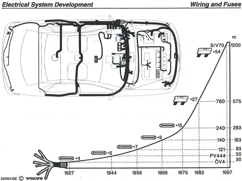
In the early years, the electrical system was relatively simple with just a few functions. Most systems operated on a 12 volt system and were operated by a switch, by adding or removing 12 volts.
You can imagine how complex the systems with wiring and control modules have become. There was a time when you could have a wiring diagram on one or two pages. Today each system is on one or two pages. The number of fuses, wires, and components have increased due to the variety of electrical functions in the vehicles today.
Control modules, sometimes called computers or even nodes, are used in the modern electrical system. Each function has a different module, such as alarm systems, cruise control, and other electrical functions. In a network, the various units are known as modules. Most functions don’t have a separate control module but rather use the control module they are close to. There are slave modules that are of smaller capacity and only operate when told by a master module. Here are some of the control modules and their abbreviations.
- ECM – Engine Control Module
- TCM – Transmission Control Module
- CEM – Central Electronic Module
- BCM – Brake Control Module
- DIM – Drivers Information Module
- DDM – Drivers Door Module
- PDM – Passenger Door Module
- REM – Rear Electronic Module
- UEM – Upper Electronic Module
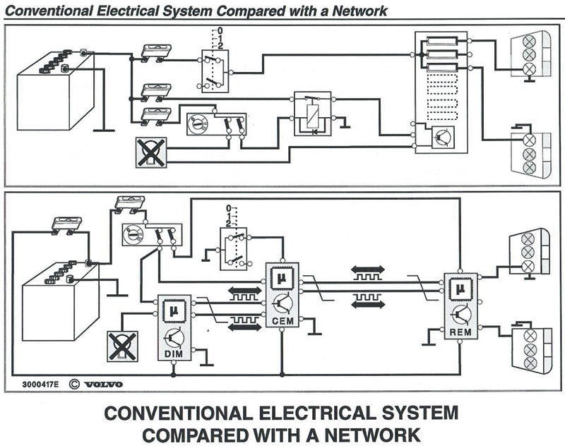
Electrical system of the past compared to the network of today
The older systems (pre-1999 models) had a number of circuits for each system. Each system would have relays, switches, and a number of leads. The current in each circuit was controlled by a switch and/or relay.
The network system was all about modules. These modules contained microprocessors and/or relays and fuses.
The Central Electronic Module (CEM) is found inside the cabin area, usually near the kick panel on either side (driver’s or passenger’s).
The Rear Electronic Module (REM) is in the rear of the vehicle, primarily in the left wheel panel.
These control modules communicate with each other depending on the function applied in the vehicle.
Using a network system can have many advantages, especially when adding or removing functions and programming function in certain control modules, such as when adjusting the interior light to stay on for different lengths of time. Being able to change and add functions can eliminate unnecessary wiring and components.
In the below example the ECM, TCM, and BCM all control their own functions. The other functions work off of these three modules. All are connected by two wires that are twisted together.
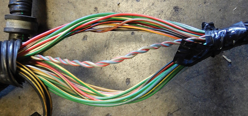
The network has two different data speeds: 250 and 125 kbps (kilobits per second). The faster speed is for the modules that require fast updating like the ECM, and the lower speed is for the electric windows. The CEM adapts the data speed between the two sections.
Messages are transmitted from all modules in order of priority. The messages are available to all modules, and the module that needs the information uses it while the other modules ignore it.
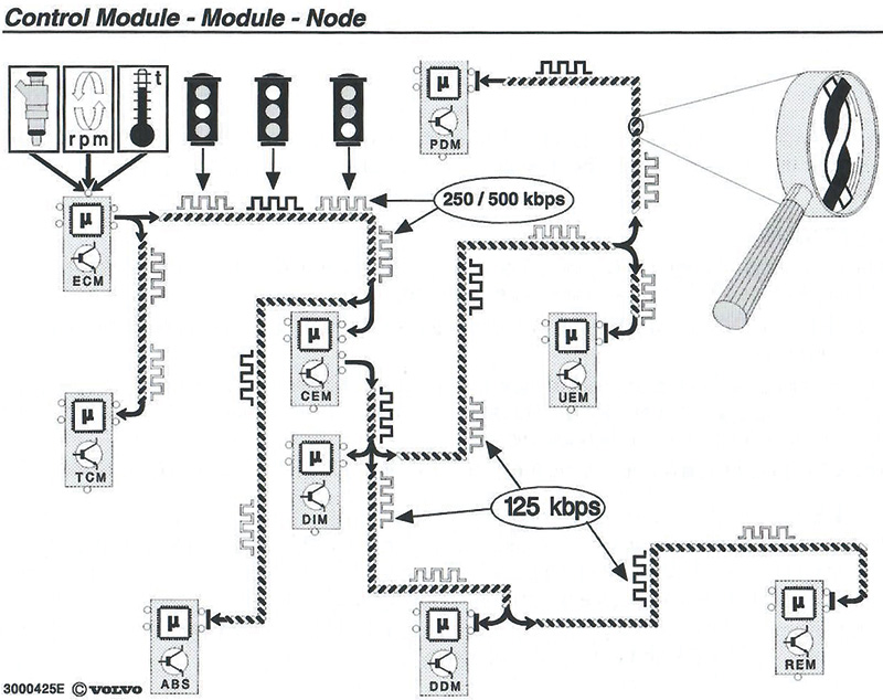
The “Control Module – Module – Node” example shows the ECM transmitting three messages in order of priority — RPM, ECT, and fuel injection quantity.
The TCM receive RPM and ECT messages and uses them for shifting points and gear selection.
The CEM receives all three messages and adapts the speed before forwarding them.
The DIM receives the messages and calculates the values for the DIM display, tachometer, and temperature gauge.
Network Changes
In 2005, Volvo changed its network to a new version. The new version had faster processors, higher quality, and lower production costs.
There is higher speed on the high speed network which is now 500 kbps instead of the previous 250.
Diagnostic communication through VIDA is now on the high speed side through the CEM.
The CEM now has two connectors — one from the engine compartment and one from the passenger compartment.
Alarm responsibility now goes through REM module and not through the CEM module.
The SWM and the SAS are now combined into one module.
The DDM and PDM now have new hardware, processors, and software.
Controller Area Network (CAN) System
The CAN System is divided into two systems — one is high speed that controls driveline and chassis functions, and one is lower speed for comfort and body functions.
The granddaddy of all modules in the network is the CEM. This master module has two processors. One is connected to both the high and low side, and the other is only for the low side. The CEM is under the dash on the passenger side for P1 S40/V50 models, behind the glove compartment. This module contains the blueprint of the vehicle.
The CEM communicates with other control modules and components via LIN and CAN communications. The CEM is connected to the data link on both high and low sides and can communicate via VIDA.
High side CAN modules include:
- BCM – Brake Control Module
- EPS – Electric Power Steering Control Module
- TCM – Transmission Control Module
- ECM – Engine Control Module
- CEM – Central Control Module
- SWM – Steering Wheel Module
- BSC – Body Sensor Cluster
High side transfer speed is 500 kbps.
Low side CAN modules include:
- AEM – Accessory Electronic Module
- CCM – Climate Control Module
- CEM – Central Electronic Module
- DDM – Drivers Door Module
- PDM – Passenger Door Module
- DIM – Drivers Information Module
- ICM – Infotainment Control Module
- OWS – Occupant Weight Sensor
- PSM – Power Seat Module
- SRS – Supplemental Restraint System
- TRM – Trailer Module
Low side transfer speed is 125 kbps.
Most functions on a P1 platform S40/ V50 are controlled through the CEM.
The standard type of serial communication in the automotive family is the Local Interconnect Network (LIN). Volvo has used serial communication between modules on the CAN network which are able to communicate for diagnosing problems with the vehicle. The control modules on the LIN bus communicate with the other networks via one of the control modules connected to the CAN bus.
Local interconnect means that a number of control modules build a local network using their own data bus. Several LIN buses can be connected to a CAN control module. The CAN control module also controls diagnostic functions and stores all the diagnostic trouble codes. The network P1 platform S40 contains ten LIN buses and can cover up to 22 control modules when activated.
Listed below are the slave modules. These units have a smaller computer capacity and only operate when told to by a master control unit. Each slave is matched up to a master control module.
| Slave | Master |
| Air Quality Sensor | CCM |
| Wiper Motor Module | CEM |
| Damper Motor Module | CCM |
| Left Rear Door Module | DDM |
| Right Rear Door Module | PDM |
| Remote Entry Receiver | CEM |
| Steering Column Lock | CEM |
| Start Control Unit | CEM |
| Gas Discharge Lamp | CEM |
| Gear Selector Module | TCM |
| Rain Sensor Module | CEM |
| Siren Control Module | CEM |
| Seat Heating Module | CCM |
| Steering Wheel Switch | SWM |
The communication speed between these module is approximately 10 kbps.
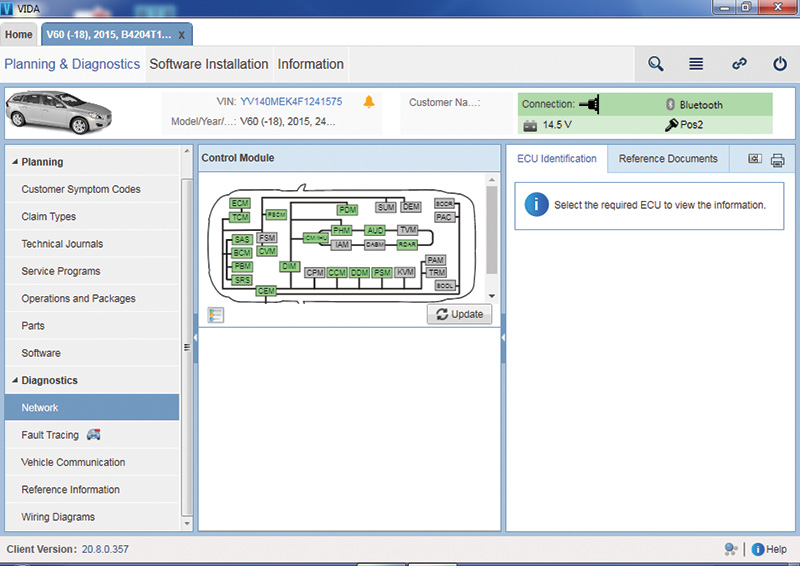
When using VIDA for diagnostics, it is critical that all control modules in the vehicle are connected and respond to the VIDA connection. When a vehicle is read out, some of the control modules may not respond. In this case you need to correct the issues with the control modules before proceeding with the actual fault tracing. The Network page helps you identify issues on the network in the vehicle. Such an issue could be a connection issue, or it could be that the hardware itself is malfunctioning.
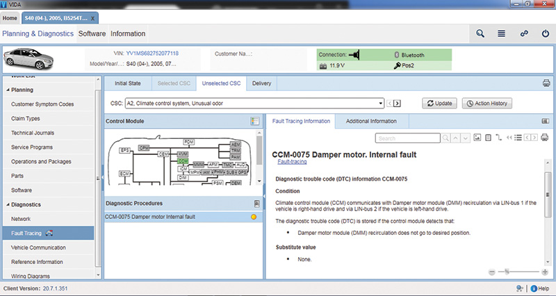
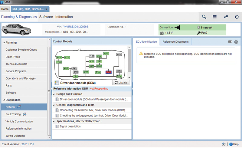
The Control Module panel in VIDA is set up in graph form. The graph reflects the vehicle’s network with all control module status at the latest readout. The color of the control modules varies depending on the status.
Green means active and the control module is responsive to communication.
Red means not responding, no communication.
Gray means the control module is not part of this vehicle’s configuration.
All related documents for the selected control module are listed in the Reference Information panel. Identification detail parameters are presented under the ECU Identification tab. These details are only accessible when selecting a control module that is responsive to communication in green.
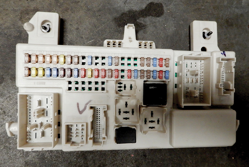
Let’s get back to wiring diagnostics. Before wasting hours of expensive diagnostic time, test all fuse circuits with a multimeter or approved test light. Remember that fuses can fail without showing signs of an obvious burnout. Since a loose or corroded fuse connector may also cause many intermittent circuit failures, thoroughly inspect and clean the fuse circuits before proceeding with your diagnosis.
When diagnosing intermittent failures, remember that suspect turn signal flashers, fuses, bulbs, and relays can be replaced more cheaply than they can be diagnosed. When diagnosing an intermittent lighting failure, for example, begin by cleaning the bulb sockets and installing new bulbs. This is much faster and easier than spending a bunch of time diagnosing the problem, especially considering that a light bulb costs a couple dollars and is probably old and needs replacing any way.
Circuit failures are usually, but not always, due to corrosion at an electrical connection or a loose wire at a connector. Use a corrosion inhibitor to clean connections and replace the connector if wires are broken.
Engine computers and body grounds should be checked first, especially if the vehicle has been in an accident.
Keep in mind that most electrical systems, when left untouched, perform very reliably. When they do fail the failure will be predictable, such as a bad current or ground connection. A blown fuse is often the problem. Most predictable failures can be solved within a couple of hours. Then, on the other hand, testing a fuel pump relay or a cooling fan switch can create multiple failures with unpredictable outcomes.
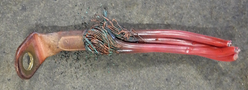
A burning wire within a wiring harness can be a problem. Obvious tampering should always create a red flag. Electrical red flags may include newly installed sound systems, electrical accessories, trailer brakes, and auxiliary lighting.
Many circuits serve more than one accessory or function. Recently it was discovered that a burned brake light fuse was caused by a loose courtesy light in the ashtray. Without a good magnetic short detector the problem would have been difficult to solve, since a relationship between a brake light and an ashtray light isn’t immediately logical. In other unlikely cases, it was learned that an instrument cluster fuse also supplies field current to the alternator. The moral of the story is to never rule out the effect of one circuit on another.
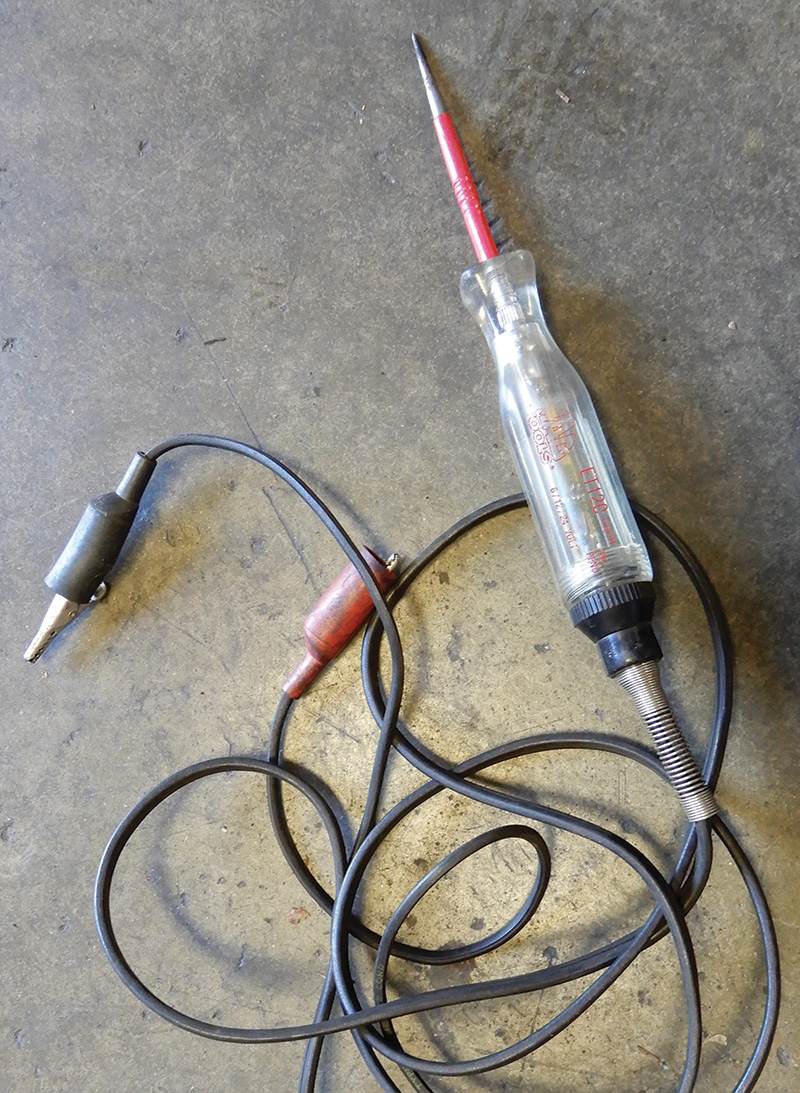
In fact, it’s not a bad idea to avoid using test lights altogether. When testing fuses, for example, you should use an LED-type test light that you can get from any tool distributor. This will indicate open or grounded fuse circuits and voltage availability. This eliminates guesswork and protects ground-sensitive electronic circuits like those used for air bag sensors.
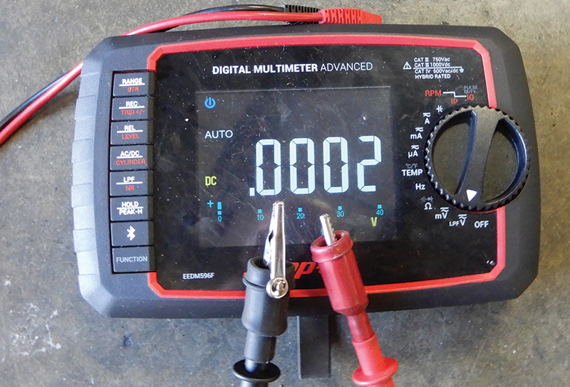
Use a professional digital multimeter with a min/max voltage feature and alarm to test intermittent failures. The min/max feature will record the highest voltage reached in the circuit and will sound an alarm each time a higher voltage is reached.
For the technician working alone, this feature is a real time saver, especially when performing a wiggle test on an intermittent wiring problem. This is the same way lab scopes are particularly useful in finding loose ground connections. During a wiggle or vibration test, loose ground connections will show up as a voltage spike.
You know how hard it is to find a pinched wire from a bolt or screw hidden under the dash. A good short detector will help you quickly locate concealed short-to-ground circuits. For about 60 dollars, it’s a great time saver for you and your customer alike.
Tips on Finding Open Circuits
An open circuit is the opposite from one that is shorted because it is similar to a cut wire that is not connected to anything. This can be tricky to find since, in an open circuit, there is no electricity flowing to help you locate the spot with a meter or short finder.
This diagnostic trick uses the car’s radio and any device with a large LCD display, like a calculator, to find an open circuit but only if the car’s antenna mast is metal. Let’s say the brake lights are not working due to an open positive feed from the brake light switch. You have already found the wire to be open somewhere by using an ohmmeter, but you don’t know where and would like to shorten the search.
Before you go ripping up the carpet and pulling interior trim out of the vehicle looking for the broken wire, grab your calculator. Start by disconnecting both ends of the line. Unplug the wiring at the light’s end and also at the brake light switch, then consult a wiring diagram to make sure any other devices attached to that circuit are disconnected.
Connect an insulated jumper wire between the antenna mast and one end of the offending wire. Tune the car radio to a quiet unused AM channel. Turn on the device you are using with the LCD display, like your calculator, and pass it down the offending wire. You will hear the Radio Frequency (RF) noise generated by the LCD display in the car’s radio speakers as you pass the good sections of wire, and this noise will fade out as you pass the break. You can demonstrate this test by tuning any radio to a quiet AM station and passing an LCD display device over the antenna.
To say the least, troubleshooting networking and wiring problems can be very overwhelming, but stick to the basics and try not to overthink them.


0 Comments