


Electrical power is everything. A networked Volvo needs all its parts running efficiently. When ALL of the codes can generate from electrical issues, where do you start?
Today, more than ever, a healthy and fully functioning electrical system is one of the most important parts of the modern car.
And, of course, it all starts with the power supply system. Today’s modern cars have some of the most sophisticated electrical systems on the planet, and some of these systems even outpace some of the latest military systems.
Yes, the advances in automotive technology are coming at us faster than ever, but some things have not changed. The cars still have tires, they don’t fly yet and, for the most part, still use a 12 volt DC battery in their starting and charging systems.
The battery voltage has not changed much, but most everything else has.
On a modern Volvo, electrical power is everything. Think of the modern Volvo’s electrical system as a small city. Just like a city, a networked Volvo needs all its parts to run efficiently.
How many codes can be generated by electrical issues on a modern vehicle?
The best answer is “ALL OF THEM.â€
We don’t always remember that, but the truth is that every single trouble code could be generated by an electrical fault somewhere in the system.
The moral of the story is that a battery and charging system test should be one of the first steps in any diagnostic jobs that come through your shop.
One of our best diagnostic tools we have today is information, and with the sophistication of these systems, we need all the help we can get.
It all starts with the customer interview; ask the right questions.
A lot of Volvos with charging system problems get towed into our shops with a complaint of a dead battery.
If the battery is not totally dead, and even if it is, hooking up a scan tool like Volvo’s VIDA software system will help you determine if there are any stored codes or data that will point you in the right diagnostic direction.
Some cars will not show any symptoms, but we still have to ask the customer the right type of questions — “How long?” and “How often?” are the basic ones. Of course a good service writer can get the right answers out of the customer the first time.
If the car was towed in with a dead or fully drained battery, the car’s network may have lost some or all of the stored codes and freeze-frame data. So a thorough customer interview can be critical and help you take the right diagnostic path.
Check those TSBs. Volvo calls them TJs or Technical Journals. There are a lot of them that cover battery drain and charging issues.
One of the more common ones is TJ 26188.1.12 which deals with a Key Off drain caused by the RDAR (satellite radio tuner) module not having the latest software update. This applies to most Volvo models 2008-2012.
The battery can drain voltage with the key off, due to the RDAR module staying awake or trying to locate a satellite radio signal, even when the ignition key is removed and the car has been locked.
The fix for this is to use Volvo’s VIDA and DICE tools to download the latest software update to the RDAR module.
Volvo Technical Journal Case Study: 2012 XC60 3.2L 81K MILES
Power System Service Warning on Dash Display and Low Voltage at Battery While Engine was Running
This car came into the shop with a customer complaint of having to jump start the battery several times in the last few days and a warning message being displayed (Power System Service Urgent) intermittently in the past few weeks.
During the initial testing, the technician performed a battery and charging system test with a Midtronics tool. The battery failed the load test (124 CCA out of 600 CCA), and the initial result of the alternator output test was low voltage (12.3 VDC) at idle.
The technician determined that the battery was over six years old and recommended that it be replaced.
We all know that a fully charged 12 VDC battery is needed to accurately test a vehicle’s charging system.
The technician then hooked up the car to Volvo’s VIDA software system and checked for codes and any stored data. The technician also used VIDA to check and see if any software updates were available for this car. The software was up to date and no relevant software updates were available.
To use VIDA to perform a charging system test, go to Vehicle Communication and select the Central Electric Module (CEM) in the Advanced tab. Click the Manual or Automatic Alternator test function and press Start after the following conditions are met.
Start the engine and allow it to idle for approximately one minute.
- Make sure that no extra electrical consumers are connected. Turn off functions that consume a great deal of power, such as the ventilation fan, heated rear window/door mirrors, heated seats, lighting, radio system, etc.
- Start the automatic test by clicking the Start button.
Values for battery temperature and voltage are read and displayed continually during the test. A number of tests are performed in which various battery temperatures are used from -30 degrees C to +90 degrees C.
Between each battery temperature, there is a delay of approximately five seconds before the voltage is read. This allows the alternator to have time to set the right voltage in relation to the set battery temperature.
The entire test takes approximately one minute. A message is displayed when the test is complete. Compare the values from the readout of battery temperature (T) and voltage (U) with the values in the table.
| Battery temperature (T)(°C) | Voltage (U), lower limit (V) | Voltage (U), upper limit (V) |
| +60 °C, +70 °C, +80 °C, +90 °C | 12.80 V | 13.60 V |
| +50 °C | 12.95 V | 13.75 V |
| +40 °C | 13.27 V | 14.07V |
| +30 °C | 13.58 V | 14.38 V |
| +20 °C | 13.89 V | 14.69 V |
| -30 °C, -20 °C, -10 °C, 0 °C, +10 °C | 14.20 V | 15.00 V |
If the voltage values generally lie below the lower limit (low voltage), redo the test at an engine speed
of 2,500 rpm.
If the voltage is within the tolerances this time, alternator function is OK, but the test indicates that the battery is not fully charged. If voltage still deviates, there is a fault in the charging system.
| Note: The readout voltage is read internally from the Central Electronic Module (CEM) and differs slightly from the alternator’s actual output voltage due to a voltage drop in the cable harness. |
A lot of the modules in the car’s network had stored codes that pointed to low supply voltage. This can be normal if the battery is allowed to discharge below 9.5 VDC.
The technician recorded the stored data and codes by using VIDA to create a report and printed it out.
The technician then got permission from the customer to replace the old battery and retested the charging system. The results were improved for the battery but the charging system voltage output was still low.
The technician then performed voltage drop tests on the battery cables and alternator wiring harness, and all the wires passed.
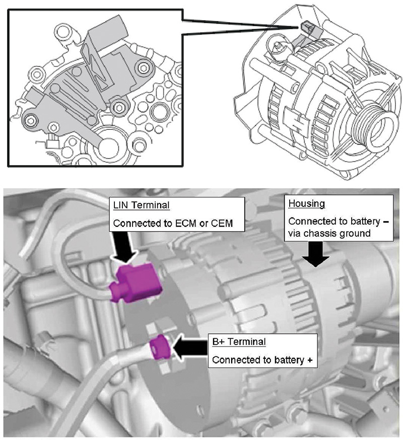
Volvo recommends that an alternator circuit voltage drop test be performed as follows:
Using a good volt/ohmmeter, measure the voltage drop between the alternator body and the negative battery post.
Next, measure the voltage drop between the alternator B+ terminal and positive battery post.
How many times have you used a volt/ohmmeter or test light that was malfunctioning or broken that caused you to take a wrong turn in your diagnosis of a problem?
Everyone’s been there. Even the best test tools can fail from time to time, so make it a habit to regularly check your test tools and electrical leads.
A good way to do this is to compare the readings of your meter against other test equipment in your shop.
Test leads don’t last forever so when in doubt, throw them out and get new ones. Some of these test leads can be quite expensive, but if they are not reliable any more how much are they costing you?
Make sure to regularly check and maintain your test equipment. It can be very common to get inaccurate readings and make repair decisions based on poor connections and malfunctioning testing tools.
The total charging system voltage drop should be less than 0.07 volts. This is the total of two measurements:
- Voltage drop from the alternator housing to the negative battery post
- Voltage drop from the alternator B+ terminal to the positive battery post
The technician made the decision that the alternator was the culprit and informed the service writer.
While the service writer was preparing the estimate for the customer, he noticed that Volvo had issued a Technical Journal TJ 26897.3.0 that talked about replacing just the voltage regulator unit. Volvo calls it an Alternator Control Unit (ACU) and not the whole alternator assembly on this year and model Volvo.
The service writer went back to the technician and brought the TJ to the technician’s attention.
The technician and the service writer decided to tell the customer that there is the possibility that they may only have to replace the voltage regulator assembly, but also told the customer that there is a chance that the whole alternator assembly would be needed and that they would know only after the alternator was removed and disassembled for inspection.
Here is How They Did it…
Alternator Removal 2012 XC60 3.2L SI 6
Of course, as with any electrical repairs, the first step is always to disconnect and isolate the negative battery terminal.
You will be removing the intake manifold plenum assembly, so you should order new intake manifold gaskets from your Volvo parts department.
You will also need a new throttle body gasket too.
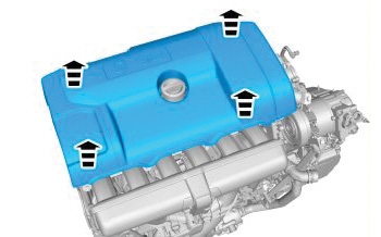
The next step will be to remove the plastic engine cover and air cleaner box. After removing the large clamp from the intake pipe, pull the air cleaner top cover off.
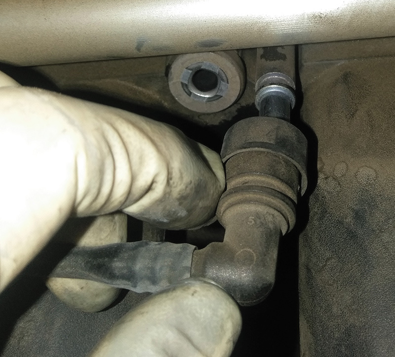
Next, use care and remove the vacuum connector at the top of the manifold by depressing the quick release fitting.
The next step will be to carefully disconnect the electrical connectors that attach to the various sensors on the intake manifold assembly.
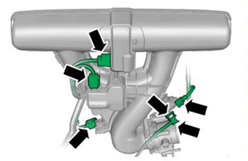
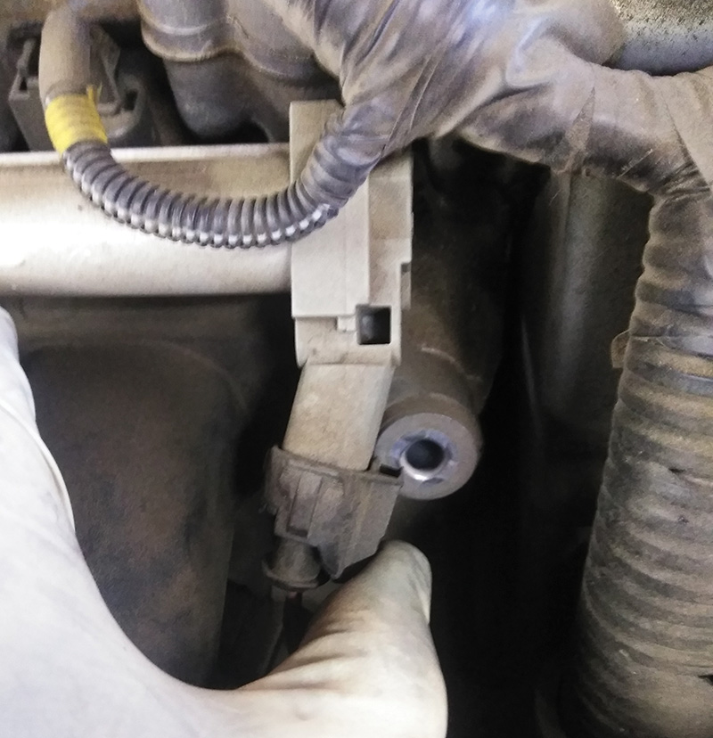
The fuel pressure sensor is not attached to the manifold assembly, but if you don’t disconnect it, the connector will get in the way when the manifold is removed.
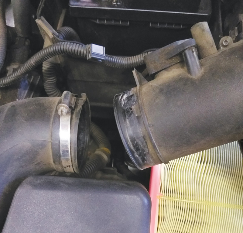
Next, loosen the two large hose clamps on the top and bottom of the main intake pipe. You can use a swivel 7 mm socket with a long extension to reach the lower clamp easily.
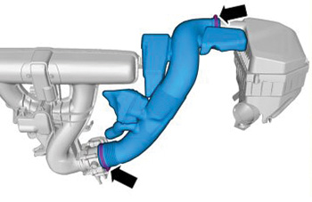
Remove the plastic intake tube and set it aside.
After the intake pipe is removed and the sensors that are attached to the intake plenum are disconnected, it’s time to remove the manifold bolts.
Remove the two bolts that hold the lower part of the plenum first.
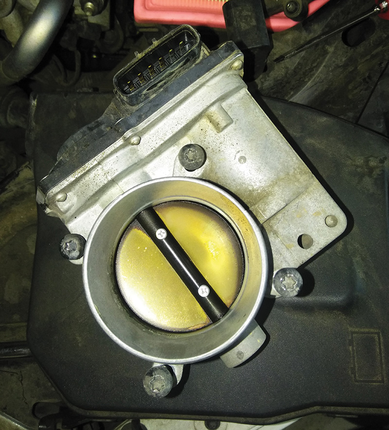
Next, to make it easy to lift out and remove the intake plenum assembly, you will need to remove the four long bolts that hold on the Electronic Throttle Module (ETM).
Carefully remove the ETM and store it on a clean, dry surface.
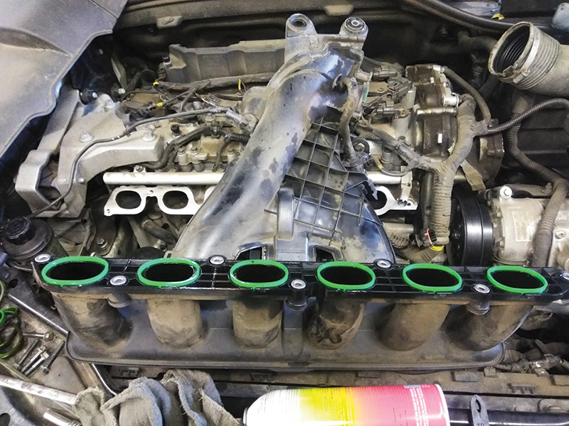
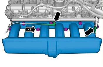
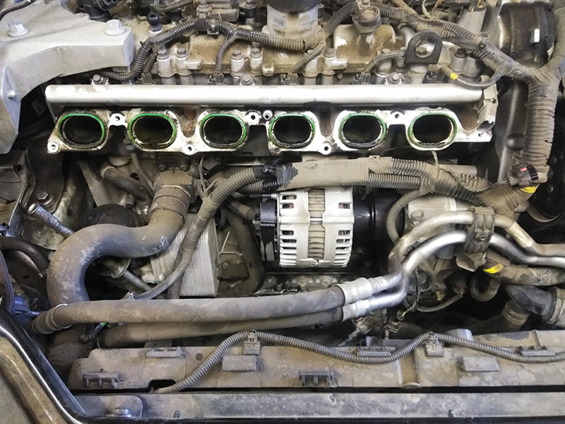
Next, remove the seven bolts that hold down the upper part of the intake manifold. You should now be able to lift out the intake plenum, giving you easy access to the alternator assembly.
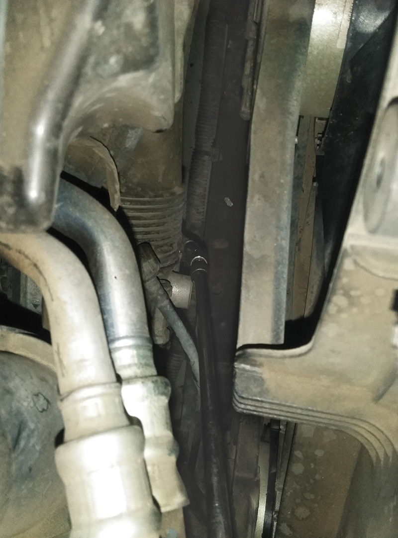
Removing the Alternator
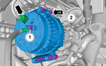
Remove the nut holding down the main B+ connector at the back of the alternator.
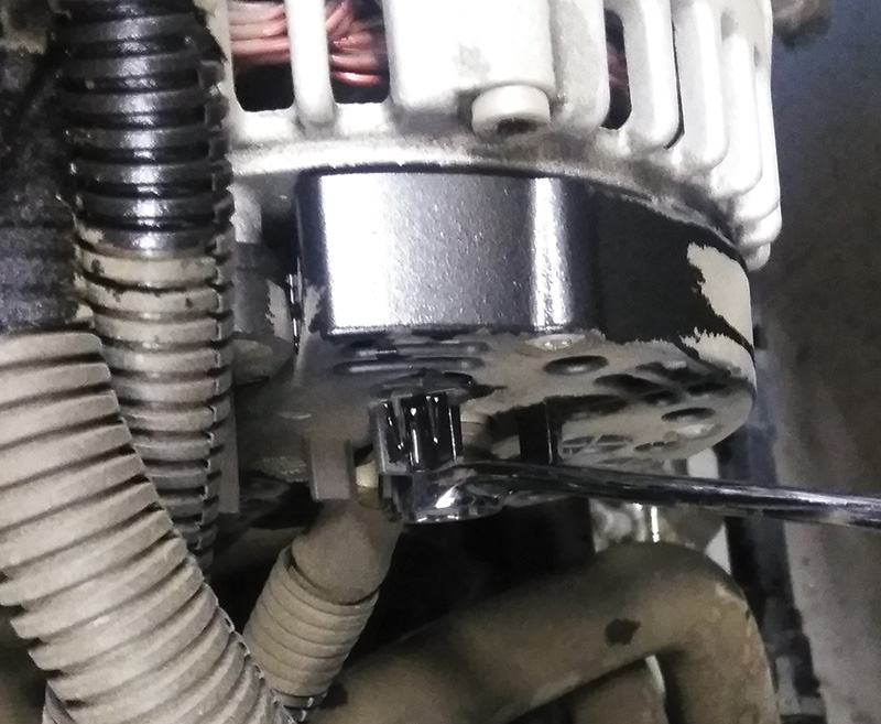
Next, carefully remove the LIN bus connector on the ACM or voltage regulator.
There are only four bolts that mount the body of the alternator. Start by removing the two on top first.
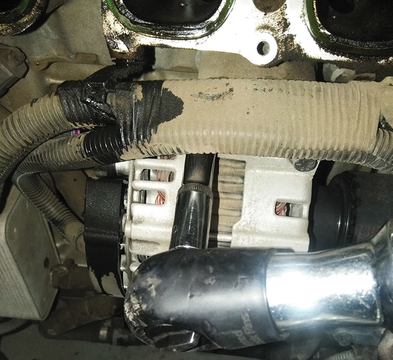
Don’t worry about the alternator falling off the side of the engine when you remove all four mounting bolts, because the lower bolt holes have aligning sleeves that will hold the alternator in place until you pry it away from the block. You will also be fighting the little circular belt when removing it.
Inspecting the ACM Voltage Regulator
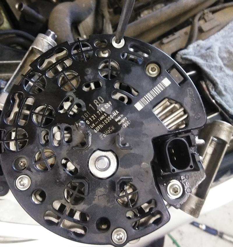
Take the alternator over to a work bench and set it up so the back of the alternator is facing up.
Start by removing the three T25 screws that hold down the plastic dust cover.
Next step is to remove the four T25 screws that secure the ACM. These screws are different lengths, so keep track of where they came from.
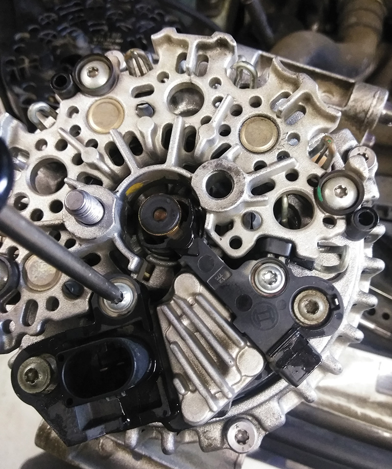
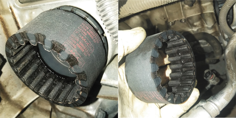
Now you can remove the ACM and inspect the contact brushes and the alternator slip rings for wear and damage.
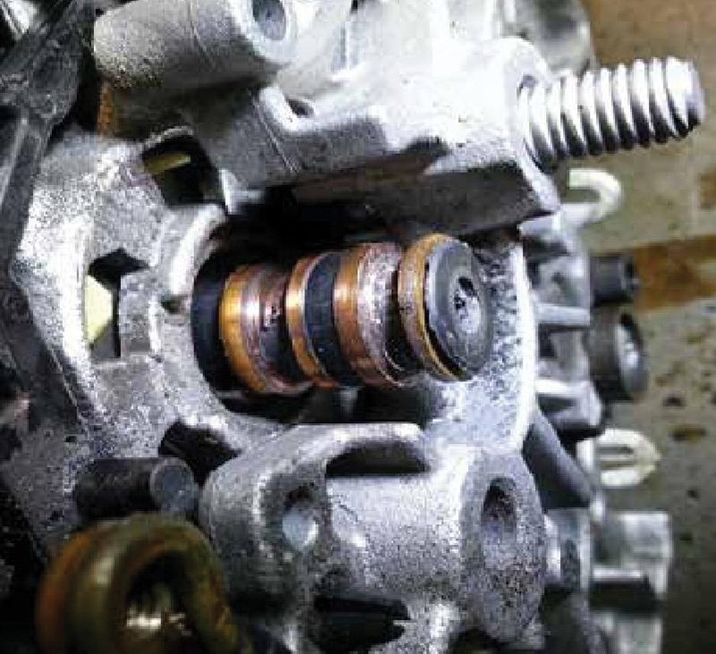
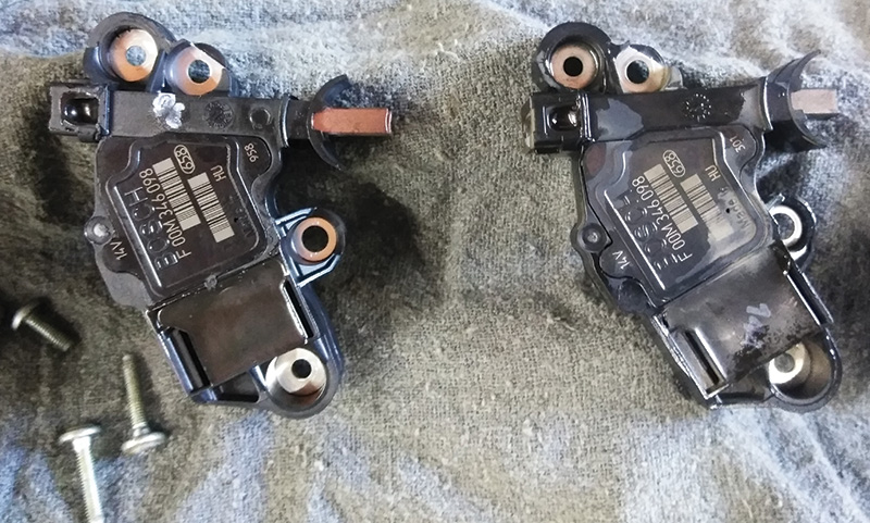
When you compare a new ACM and a malfunctioning one, you will usually see that the contact brushes are uneven and well worn. This is also a good opportunity to evaluate the condition of the alternator drive clutch. These clutches can stick or even fail completely. As a result, the gear on the engine side can loosen, so that the alternator no longer spins or charges. Replacement drive clutches have reverse threads and are not usually included with replacement alternators.
Install a new Volvo ACM unit and reinstall the four T25 screws and torque to 15 Nm.
Next, install the alternator dust cover and three screws.
Tighten to 15 Nm.
Install new belt on the alternator input drive gear.
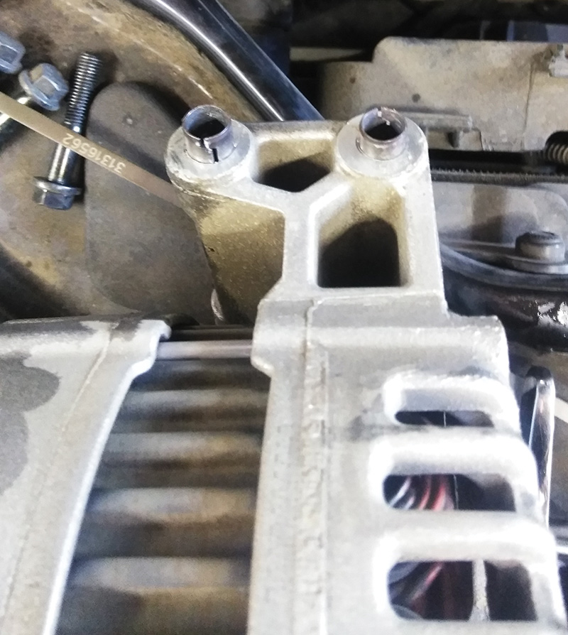
You will have to slide the alternator onto the belt gear on the engine while lining up the lower bolt holes with the alignment sleeves. This can be challenging.
You can use a 10 mm dowel to help line up the alternator body.
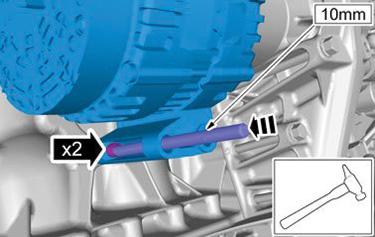
Be patient and take your time in this step. Make sure to start all four alternator mounting bolts before you tighten them to avoid cross threading them.
Tighten #2 to 24 Nm.
Tighten #1 to 15 Nm.
Install and tighten the nut for the B+ cable and then plug in the harness connector to the regulator ACM.
You can now reassemble the intake manifold and air cleaner assembly. Make sure to use new gaskets and torque the seven manifold bolts to 15 Nm.
Make sure that the car’s battery is fully charged before you hook up the negative battery clamp.
Retest the charging system output to check your work.
Reset the clock if needed and test drive the car.
In some cases, you may need to use VIDA to reinitialize the power window positions.


Tech tip: Check the torque on the gear/sprocket, occasionally it’s loose. I recommend little blue-Loctite. Thanks for a this tech-info.