


Using VIDA, we can limit time spent on diagnosing a Battery Monitoring Sensor (BMS) and ensure the vehicle is repaired correctly.
Although charging systems seem pretty straightforward these days, these systems can become very technical and sometimes hard to diagnose. Volvo vehicles equipped with the Battery Monitoring Sensor (BMS) can sometimes be tricky also, but with the help of VIDA we can limit the time spent on a vehicle and be sure that it’s repaired correctly.
Checking battery operation can be done with VIDA if the vehicle is equipped with the battery monitoring sensor. Visual inspection is very important as is making sure all connections are clean of any corrosion. If there are any signs of new leakage or battery leakage that has already dried into powder, you will need to clean completely and the battery should be replaced.
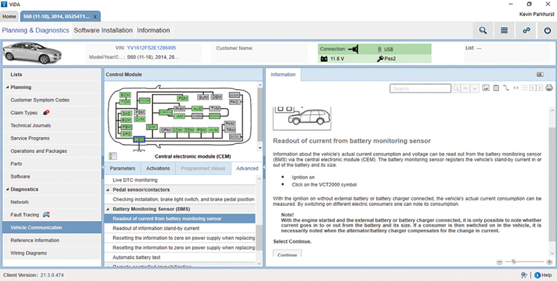
To check the battery system in the vehicle with VIDA, connect VIDA and run Profile, go to Communication and click on Central Electronic Module (CEM). Scroll down to the Battery Monitoring Sensor. Here you will be able to monitor and check different readings of the system.
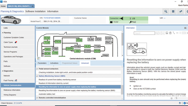
When replacing the battery, you will need to go into VIDA and then go to Advanced Settings, then scroll down to Battery Monitoring Sensor. Select resetting the information to zero on the power supply when replacing the battery or Battery Monitoring Sensor. There is also an automatic battery test that can be used to check your customer’s battery.
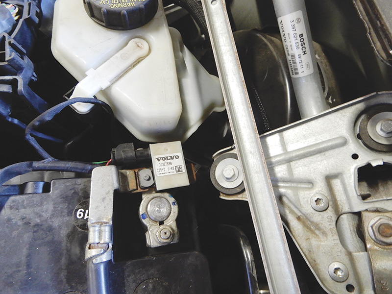
As an example, here we’ll check the battery charging during operation on a 2012 Volvo S60 five-cylinder engine equipped with BMS. We need to make sure that there has been no electrical equipment connected directly to the battery negative terminal. If there is, it is necessary to remove it and connect it to the correct place on the vehicle.
If there is electrical equipment connected in line at the negative terminal, the BMS will not have the correct state of charge.
Check the state of charge in the battery using VIDA. If the battery monitoring sensor has been disconnected and then connected again, the state of charge defaults to 80%.
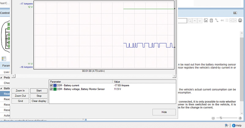
Warm the vehicle up and check the battery current using VIDA. Make sure that the battery current is positive; if the current is low the battery might need recharging or possibly, replacement.
If the battery monitoring sensor is replaced, you can reset it also by disconnecting the sensor and reconnecting.
Battery discharging while the vehicle is parked could be caused by a software issue and could be cured by adding new software to the CEM. In some instances, the battery draining could be caused by a component elsewhere in the system.
To check the individual components in the system, you will need to use the 10 volt scale on a multimeter, and check the CAN network. To do this, the vehicle must be powered down and locked. With the front driver’s door open, use a screwdriver to lock the latch. Let the vehicle sit for a few minutes, maybe five or so. This will let everything go into sleep mode, and then voltage in the CAN system should be zero. Communication on the CAN network will be 0.5 to 4 volts.
Measure voltage at the diagnostic socket to which DICE connects. The low speed CAN network can be checked by connecting your meter to terminals 3 and 11. The high side can be checked at terminals 6 and 14.
Checking accessory installation, low battery voltage
This symptom fault tracing only applies to the S40 2004-Present/V50/C30/C70 2006-Present with structure week 200923 and onward, as well as the S60 2011-Present/V60/XC60/S80 2007-Present/S80L/V70 2008-Present/XC70 2008-Present with structure week 201005 and onwards that display the following symptoms:
- LM, 12 V main battery/dead battery
- LN, 12 V main battery/weak or low electrical power
- LO, alternator and charge regulator/power supply problems
If electrical accessories are installed, it is very important to ensure that these accessories are grounded after the BMS and not before the battery’s negative terminal. If the battery’s negative terminal is used as a ground point, there is a risk of the BMS giving incorrect data to the alternator. This can lead to reduced charging voltage at the alternator.
Suggestions for alternative ground points for accessories are:
- For S40 2004-Present/V50/C30/C70 2006-Present ground points 31/110, 31/112, 31/114 are recommended.
- For S60 2011-Present/V60/XC60/S80 2007-Present/S80L/V70 2008-Present/XC70 2008-Present ground point 31/AL is recommended.
Remedy as necessary.
Let’s go in another direction. Let’s say you have a code in the CEM because the battery is over charging. This will happen if the CEM detects that the battery voltage is over 16 volts.
This could be a battery problem or the alternator, and possibly both. Make sure the drive belt and tensioner are not damaged and look to be OK.
Check the battery to see if it has the proper charge. If not, charge the battery. Disconnect the battery from the vehicle before charging and always disconnect the negative terminal first. If needed, replace the battery. Once the battery has been charged correctly or replaced, connect it to the vehicle. Start the vehicle and check the voltage. If the voltage is still too high, there could be an alternator problem or a fault in the Alternator Control Module (ACM). Replace as necessary.
Checking voltage drop between the battery and the alternator
When you have a vehicle that is not charging correctly, and the resistance in the circuit is too high, in certain circumstances you will get a code to check the resistance in the wiring harness.
Expose the battery and check for any corrosion at the cables. If you can see corrosion inside the cable, you will need to replace this cable.
To check the voltage drop on the cable between the battery and alternator, you will need your multimeter for this task.
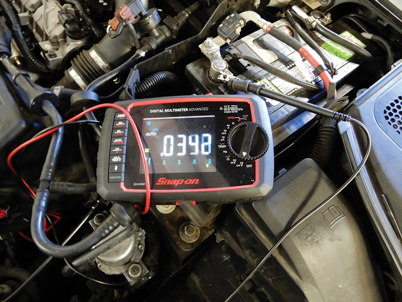

Now connect your meter between the battery positive terminal and the alternator. Start the vehicle and maintain a constant speed around 2,300 rpm. Make sure to turn off the radio, climate control, and any other power consuming components. Check the voltage drop and record.
Then do the same on the negative side of battery, and add up your values. The total value should not be over 0.72 volts.
Battery warning messages in DIM
There are two different battery warning messages that can appear in the Drivers Information Module (DIM).
- Low battery
- Low battery power save mode
For vehicles equipped with BMS, when a low battery message appears at the DIM, one of the following has happened:
- Key out of ignition and the infotainment system is on, battery State Of Charge (SOC) is less than 60% for more than 30 seconds.
- Key in ignition and turned to position I or II the battery SOC is less than 60% for more than 30 seconds.
The message “Low Battery Power Save Mode” appears at the DIM when the following conditions occur:
- Key out of ignition and infotainment system on, the SOC is less than 55% for more than 120 seconds after low battery light is on.
- Key in ignition and turned to position I or II and the battery state of charge is less than 55% for more than 120 seconds.
For vehicles with BMS, if the battery monitoring sensor is disconnected and then connected, the battery’s state of charge is set to 80% until the next calibration when the vehicle has been switched off for at least four hours.
The overall purpose of the alternator is to ensure the charging system has current while the vehicle is running and the battery maintains charge.
The alternator creates alternating current which is converted into direct current. There is a built-in regulator inside the alternator, the Alternator Control Module (ACM). The regulator communicates with the ECM via the LIN system.
The charge indicator light coming on means there is a problem in the system. The system is diagnosed through the CEM and the ECM.
Check the battery and all cables and terminal connections for corrosion or looseness. With the vehicle running, the correct voltage should be 12.8 volts to 14.2 volts, depending on the speed of the engine and the components in the system that might be on.
To understand the alternator, the components that make it up are:
- Stator
- Rotor with slip rings
- Integrated cooling fans
- DC bridge
- Charge regulator
- Front pulley
Depending on the make and model, some of these alternators are freewheeling.
The terminal connections at the alternator on a 2012 Volvo S60 are:
- A 1 B+ Main power to alternator
- B 1 Engine control module (ECM)
- B 2 Not used
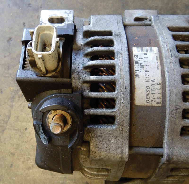
The alternator has a regulator that is fitted into the rear of the alternator (also known as the alternator control module, or ACM). The ACM can be replaced without replacing the complete alternator.
Once the vehicle is started, the ACM communicates with the ECM via LIN communication. The ECM then communicates with the CEM via the CAN to regulate the alternator output.
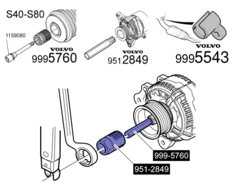
Certain alternators have a freewheel feature between the rotor shaft and the pulley. These alternators can be identified by a cover over the center pulley nut. The freewheel rotor shaft can only rotate freely in one direction; this minimizes any jerking in the belt setup.
Checking the function of the alternator freewheel while running the engine
Start up the engine, making sure to shut off all power consuming components. Run the engine to 3,000 rpm. Check to hear just a faint clicking noise at the alternator freewheel; this is the engaging and disengaging of the freewheel. Shut the engine off and immediately check to see that the alternator is still rotating. If the alternator is still rotating, then the freewheel is fine.
To check with the alternator off the vehicle, rotate the pulley counterclockwise, then brake the pulley. The freewheel will grip the alternator shaft turning counterclockwise.
Stopping the rotation, the freewheel pulley should release so that the alternator shaft continues to spin.
Using VIDA to check the alternator function
Checking the alternator function on VIDA will differ depending on whether the vehicle is equipped with BMS or not.
VIDA will give you the option to test the alternator either with BMS or without. The CEM works with the ACM to regulate the alternator’s output.
The temperature of the battery helps determine the output of the alternator which is controlled through the BMS.
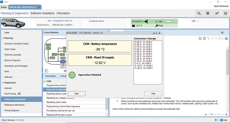
To test the alternator function when the vehicle is not equipped with BMS, use the manual test of the alternator in VIDA. Go to CEM, Advanced tab B. Scroll down to Quick Test of Alternator, then go to Manual Test.
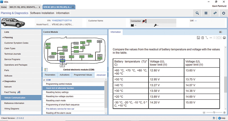
Turn off all electronics in the vehicle. Start the vehicle and click on Test. Compare the values from the readout of the battery temperature and voltage in the “table for manual battery test” image.
If the voltage is low, redo the test at an engine speed of 2,500 rpm. If the voltage is within tolerance, the alternator is good at this time.
In the table there are values for temperature and voltage; select a temperature value and give the alternator a few seconds to read voltage properly. You can check each value to test the alternator at different temperatures.
The CEM checks the battery voltage, and if the voltage stays at 11.6 volts or less for longer than two minutes, an error code will set the Check Engine light.
If the CEM detects voltage is 16 volts or higher, this too will set a Check Engine light, and you will have to diagnose the problem with the charging system.
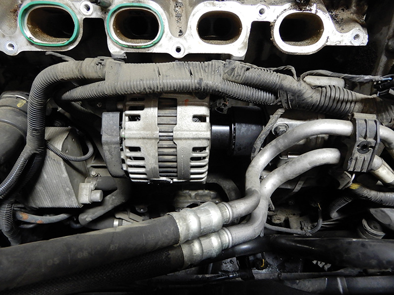
On Volvo’s six-cylinder engines, the alternator is connected to the engine block underneath the intake manifold and is driven by a gear transmission connected to the timing chain assembly.
The alternator on these six-cylinder engines operates the same way; the mounting is the only difference.
When replacing an alternator on a six-cylinder engine, the first thing to always do is disconnect the negative side of the battery. Disconnect the hose from the air filter housing to throttle housing and set it out of the way.
Disconnect all electrical connectors to the intake manifold and throttle housing. Be sure to remove the two bolts at the bottom of the intake that secure the unit to the block.
You will need to drain the coolant from the vehicle. Remove the coolant hose that is connected to the block at the middle of the intake manifold. Remove the seven bolts that hold the intake onto engine. Here it might be a good idea to remove the fuel pressure sensor so not to damage it. Remove the intake.
Remove the two electrical connectors at the alternator. Four bolts hold the alternator to the block; remove these four bolts and remove the alternator from the vehicle.
When installing a new Volvo alternator, be sure to replace the small belt and any pulleys that might show signs of wear.
Also, when installing a new Volvo alternator, be sure to install the two dowels between the alternator and the engine block. Properly install both dowels into the engine block and tap into place. Make sure both dowels are correctly installed; otherwise premature coupler wear can occur. Also replace the small belt and any pulleys that might show signs of wear.
In some instances, the alternator might not be bad, but the freewheel pulley may be damaged and needs to be replaced. You will need to remove the alternator from the vehicle to do this.
To remove the pulley, first remove the front cover and use special tools to hold the shaft and remove the pulley. Install the new pulley and torque to 80 Nm.


0 Comments