
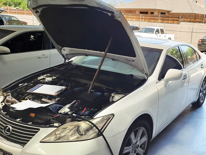
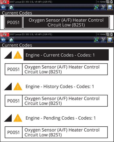
Some months ago, I was called to a shop to assist in the diagnosis of a 2007 Lexus ES350 (Figure 1) with a code P0051, “A/F Sensor Heater Control Circuit Low (B2S1)†(Figure 2). We’ll call this shop “Shop B.†Another shop, let’s call them “Shop A,†had installed a used motor but had been unable to diagnose the P0051 that appeared after the engine installation. Shop A then sent the vehicle to Shop B for troubleshooting. Shop B also had difficulty, so they called me.
I wasn’t worried because circuit codes are usually pretty easy to diagnose. Little did I suspect it would be the start of a massively frustrating saga. However, it did provide me with a great lesson, and now you can share the same lesson, without all the frustration.
But before we start, let’s go over a little background on AF (Air/Fuel) sensors as opposed to the conventional zirconia oxygen sensor.
A/F Sensor Primer
Many technicians have struggled with the diagnosis of AF sensor codes like P2195 through P2198 (AF sensor stuck lean or stuck rich, bank 1 or bank 2.) One of the difficulties in troubleshooting AF sensors is that Toyota and other manufacturers pick a range of voltages to display in live data that indicates the measured air fuel ratio. However, the actual output of the A/F sensor is amperage, not voltage. If you were to measure the voltage at the sensor, you’d find it doesn’t match the voltage reading in live data. Toyota explains this in their service information:
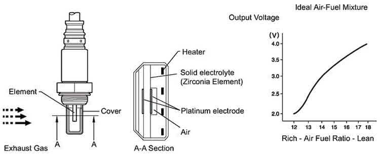
“The A/F sensor generates voltage* that corresponds to the actual air-fuel ratio. This sensor voltage is used to provide the ECM with feedback so that it can control the air-fuel ratio. The ECM determines the deviation from the stoichiometric air-fuel ratio level, and regulates the fuel injection time. If the A/F sensor malfunctions, the ECM is unable to control the air-fuel ratio accurately†(Source: TIS).
Notice the all-important designation of the footnote which reads:
“*: Value changes inside the ECM. Since the A/F sensor is the current output element, a current is converted to a voltage inside the ECM. Any measurements taken at the A/F sensor or ECM connectors will show a constant voltage.â€
If you were to measure the voltage output of the A/F sensor, you’d find it to be 3.3V all the time, regardless of the voltage displayed by the scan tool, which might be confusing. However, if you measured the current output, you’d find that it changes with the air/fuel ratio. It’s possible to measure the output with a microamp probe, but that’s an expensive tool, and there are no published specifications.
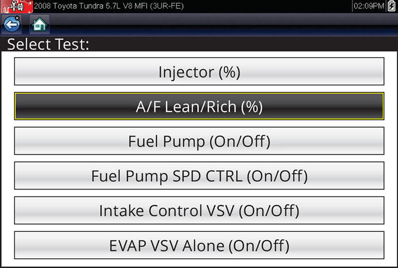
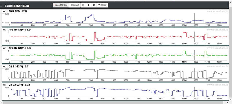
Instead, most technicians will simply look for agreement with other sensors. If the B1S1 AFS reads 4.99V (full lean) and the B1S2 oxygen sensor reads 0.9V (full rich), one must be wrong. On V6 engines, the A/F sensor readings can be compared bank to bank. (However, if a code has set, the data may display a substitute value based on the “good†sensor, so clear codes first.) You can also use active tests to drive the mixture rich or lean while monitoring the A/F sensor output in live data. Finally, you can snap the throttle or road test the vehicle to determine if the sensor will move through its full voltage range, usually around 2V–4.5V.
Back to the Case Study
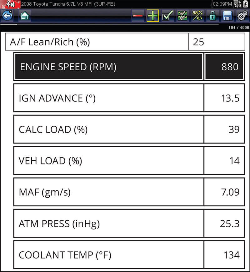
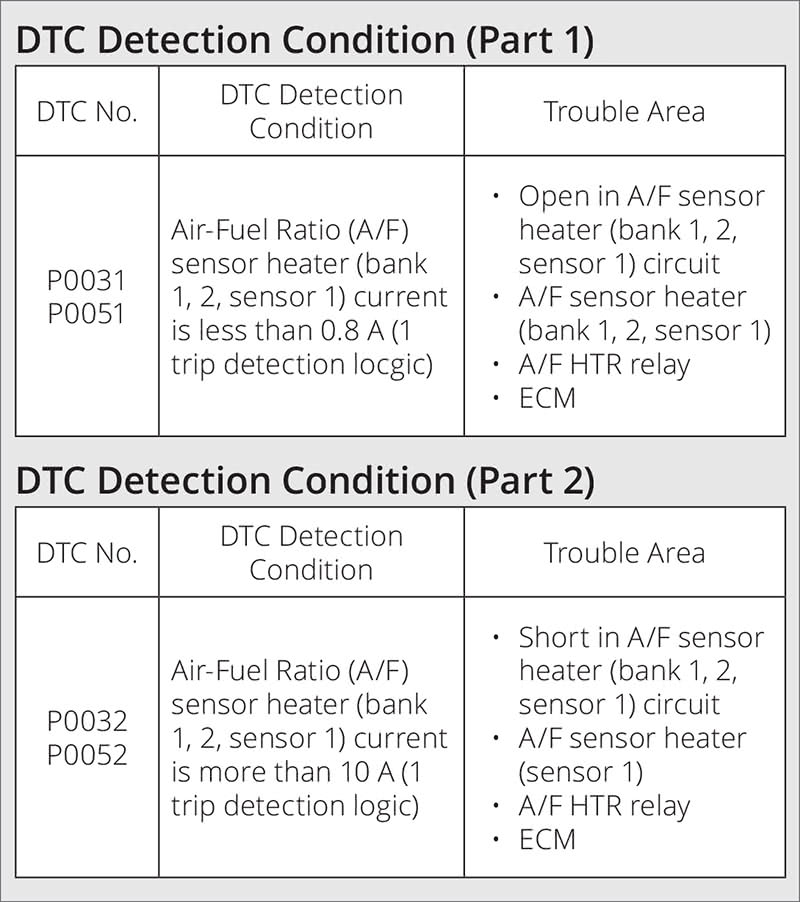
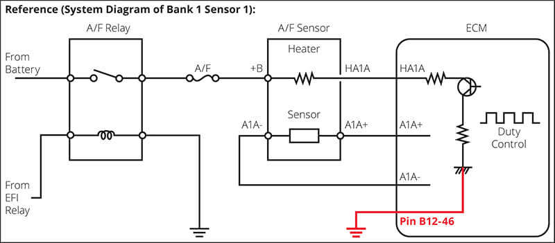
So far, we’ve covered problems with A/F sensor output, but for the A/F sensor to work, the heater must work. Our P0051 is a B2 A/F sensor heater code, not an output code. Time to get back to the problem at hand. According to TIS, P0051 will set any time the current through the B2S1 heater circuit is less than 800mA (Figure 7). The ECM provides pulse width modulated control on the ground side of the heater element. The other side is powered by the A/F sensor relay.
Most often, circuit codes are caused by either an open or high resistance in the component. This happens so often that technicians tend to jump to the conclusion that a circuit code is really just a component code and will replace whatever component is named in the code description.
That’s what had happened with this vehicle. Shop A had already installed a new B2 A/F sensor. Shop B had replaced the same part again with similar results; the P0051 kept coming back. At this point, it’s safe to assume a 3rd A/F sensor probably won’t cure our P0051.
P0051 Diagnostic Flow Chart
The diagnostic flow chart went like this:
1. Check A/F sensor heater resistance. OK? Yes. Go to 2.
2. Check for power at the sensor from the A/F relay. OK? Go to 7.
7a. Check heater wire from sensor to ECM. OK?
7b. Check heater wire to ground. No ground contact? Go to 8.
8. Clear codes and see if the P0051 returns. Yes? Replace ECM.
Doubt
At this point, using the chart from Toyota, this vehicle needs a replacement ECM. But my antennas were up for two reasons. First, Toyota’s ECMs are usually quite reliable. Second, an engine was installed in this vehicle, so some sort of pinched wire is not hard to imagine.
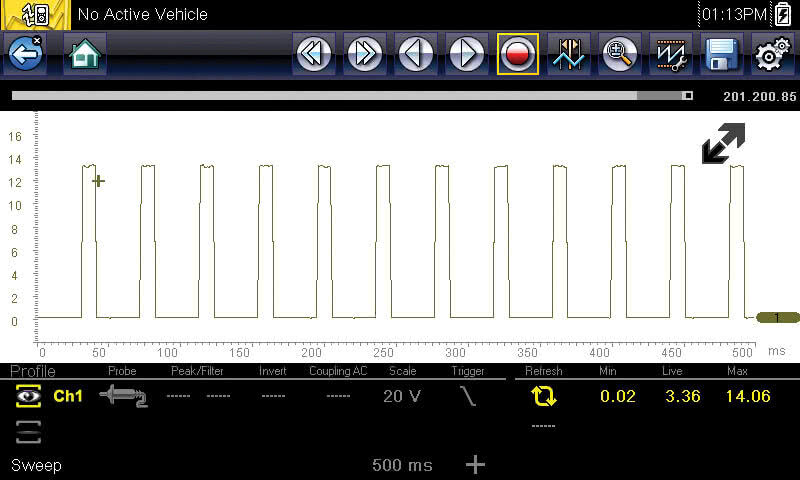
When the ECM is driving the A/F sensor heater, you’ll normally see a square wave on the heater wire from the sensor to the ECM. The B1 sensor waveform pictured is normal (Figure 9), which you’d expect since there isn’t a B1 code. B2 on the other hand is just a straight 13.7V line. The ECM wasn’t grounding the A/F sensor heater at all on our problem bank.
I first used my Fluke 88 in amps mode to activate both heaters with a 100% duty at the ECM Pins 86 and 109 respectively. The service information indicates a resistance reading of 1.8 to 3.4 ohms. However, I vastly prefer to activate the circuit by turning the key on to power and grounding the circuit by means of the DMM set on amps.
Both of my AF sensor heaters draw about 4 amps at 100% duty-cycle, falling well within parameters of less than .8 amps or more than 10 amps (refer back to Figure 7). More importantly, they are exactly equal, eliminating the possibility that a wire is pinched somewhere.
I have one more test that I think should clinch an ECM fault. Right at the ECM, I swapped the Pins 86 and 109 so the heater circuit for Bank 1 will drive the heater in Bank 2. It does so without a problem. Time to install an ECM, or so I thought.
I Pulled the Trigger and Shot My Foot
Two used ECMs later, I’m out of ideas. The sensor is good, the wires are good. Three ECMs can’t all be bad in the exact same way. And the same P0051 remains, even when I swap B1 & B2 heater wires in the ECM connector. I recommended Shop B to get rid of the vehicle and let Shop A do the suffering. I know better than to marry a problem car that I have no particular responsibility for. I hate to lose, but I also like to pay bills.
A Few Months Later
More than two months go by, and I have relegated the unfortunate Lexus to my memory of unfixable vehicles. One day I get a call. Shop D (as it turns out) has been sublet a vehicle from Shop C for purposes of readying a replacement ECM purchased from Lexus. Since I’m their programming guy, they call me to do the job.
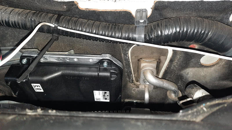
I arrive at Shop D and install the new ECM on the firewall location. As I’m doing so, I notice some replacement wiring that looks familiar. (Figure 10) Before completing the job, I asked the Shop D service writer if the Shop C has requested anything beyond the ECM preparation (which turned out to be nothing more complicated than a VIN write; no anti-theft preparation or tool use necessary with a new OE part.) They said no, so I went ahead with my work.
After starting the vehicle a couple of times with the replacement ECM, I notice the MIL is on, so I go ahead and check for codes. As soon as I read a P0051, I have a deja-vu moment. This is the same car I gave up on a months ago! Two used ECMs and now a third new ECM haven’t fixed this vehicle. Something else is wrong but what?
I had searched for TSBs and cases on Identifix looking for an assist, but no luck. However, as I don’t like failing much, and Shop C really wanted the help, I agreed to give is a shot, again.
I told Shop C that I had one idea left and gave very little hope that it would prove true, but I’d be willing to test it. Maybe the B2 A/F sensor had an undocumented ground, separate from the B1 and rear O2 sensors. It seemed unlikely, but everything up to this point didn’t make sense to me, so why not check.
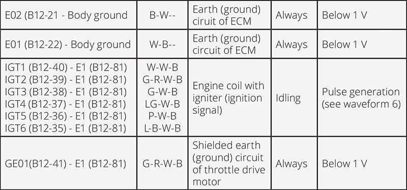
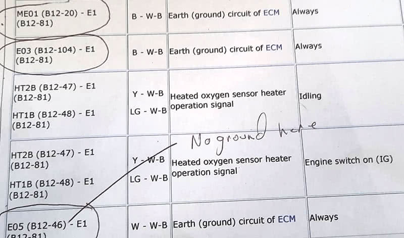
My method for checking grounds isn’t high-tech. I started by going to the pin chart for the ECM and circling every ground wire. (Hint: There are lots!) Some of them helpfully define what circuit they work for. See Figure 11 for an example.
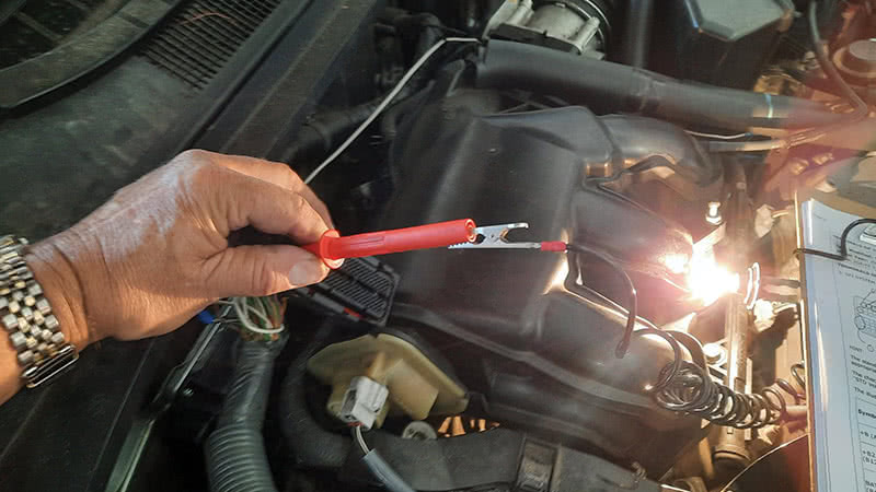
Now, I don’t like the Toyota suggestion to test the voltage on the pin with a voltmeter referenced to ground (Pin 81, another potential fault circuit). It might work fine if there is current flowing, but since I don’t know that, I prefer to flow my own current through a test lamp, which incidentally happens to be a headlamp bulb that draws close to 4 amps — just like my heater circuit.
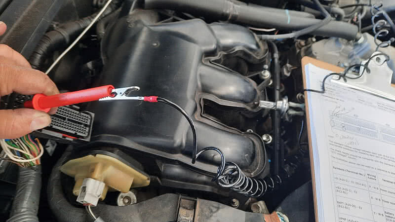
I work my way down the chart by hooking my test lamp to battery positive and then touching my probe to each of the ground pins at the ECM connector (Figure 12).
This is tedious work, confirming the pins and checking for the lighting of the test lamp, and I’m not spurred on much by my skepticism that this is a waste of time. However, when I get to Pin 46 my test lamp does not light up (Figure 13).
I made a note on my chart of the missing ground, which raised my hopes a bit, but not much (Figure 14).
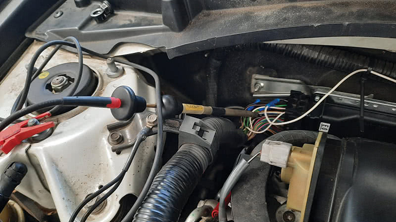
I had already inspected all of my ground connections on the cylinder heads in case the engine installer had left something loose. Nevertheless, Pin 46 is bad and won’t light my light. There are signs under the hood of rodent activity which makes me suspicious that a chewed wire is probable, but a visual inspection of the loom holding this ground wire doesn’t show anything. Besides, does this missing ground have anything to do with my problem? I decide to apply a temporary ground and find out (Figure 15).
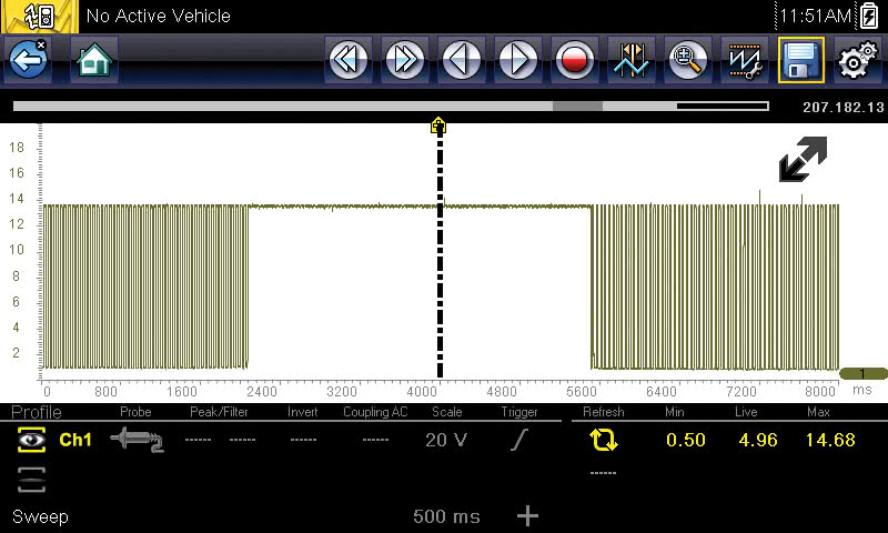
When I applied the ground, I at first just started the engine and got a surge of excitement after the second key cycle with no MIL illuminated. But lest I go off track, I hooked up my scope to the control wire on Pin 109 again and fired it up. You can imagine how excited I was when I saw the square wave. Plus, removing the temporary ground caused the duty-cycle to disappear, then reappear when I reconnected the ground (Figure 16).
The Moral of the Story
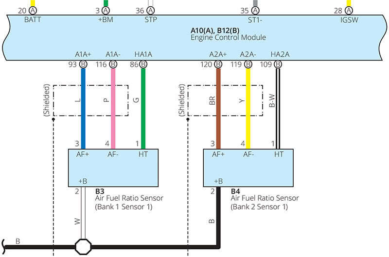
I had found the problem! Lexus uses a single wire to do nothing else but provide the ground for the B1 A/F sensor heater. It would have been very handy if this had been identified in the diagram provided in the P0051 code description (Figure 17). Regardless, here’s the lesson I promised at the start of the article: Before replacing an ECM, find the “Terminals of the ECM†chart on TIS, and check every single ground before getting a new ECM.
By Edwin French

Thank you so much for your post, i fixed my coworker 2007 lexus es350 same exact problem, the ground juction B32 plug was lose from ground cap, someone reinstall the engine and did not plug all the way down, Pin 46 white wire grounded to the juction B32 plug.
So did you find the fault with the existing ground and repair it or just splice in a new ground? No judgement , I’ve done both depending on the situation, just curious. 😊
Hi Ted,
This came from the writer:
Edwin, Loved the fact that you found the answer to your problem, lots of perseverance! I had a similar issue with a neighbor’s 2004 Chrysler Sebring. It was a P0134 for B1S1 heater circuit. This heater is constantly grounded, the positive side is duty cycled through the ECU. I got to look at the vehicle after the second O2 sensor and first engine ECU. I scanned the circuits involved and everything appeared to be okay when I was looking at it. Finally I got it to act up, the ground to that sensor was intermittent. Repairing the faulty ground wire finally fixed the problem.