


In this article, we will go over the Volvo Rear End Auxiliary Drive (READ) assembly, how it works and how to maintain it. The READ assemblies on these six-cylinder engines are unique to Volvo.
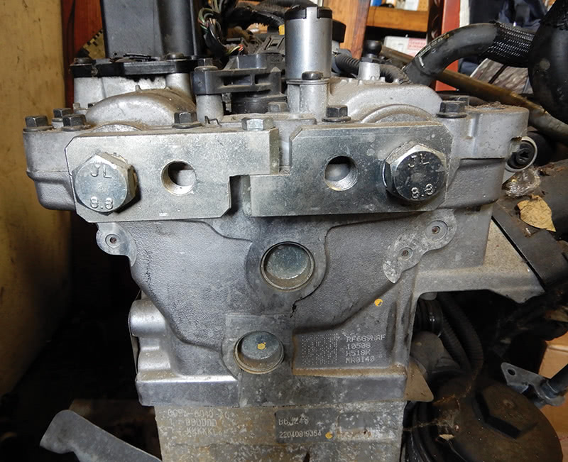
We go through inspecting the READ assembly, and how to deal with a potentially expensive repair for the customer. The READ assembly is the gearbox on the side of the engine, closest to the radiator.
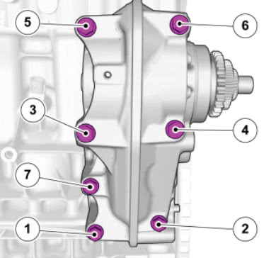
The gears in this assembly are all driven by the crankshaft. The READ assembly diagram shows each gear wheel and its function.
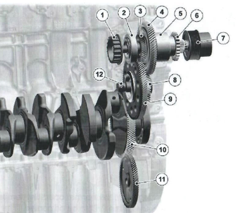
Sleeve Connection, Alternator Front Bearing Gear Wheel, Auxiliary Unit Shaft (Inner shaft) Gear Wheel, Cam Driving Shaft (Outer Shaft) Rear Bearing Gear, Cam Chain Pulley Gear Wheel, Drives the Cam Driving Shaft (47T) Gear Wheel, Drives the Auxiliary Unit Shaft (94T) Gear wheel, Crankshaft (99T) Gear Wheel Oil Pump (76T) Intermediate Shaft
The gear housing is machined to the engine block. The unit contains a shaft inside a shaft. The intermediate shaft (12), which is joined to the crankshaft gear wheel (10), drives the two shafts. The intermediate shaft has a small and large gear wheel. The small gear wheel drives the outer gear wheel on the cam drive shaft (4). The large gear wheel drives the inner gear wheel on the auxiliary unit shaft (3).
Being of different sizes, the shafts will rotate at different speeds. The oil pump connected to the gear wheel (11) is driven from crankshaft gear wheel (10).The gearbox READ assembly links the timing chain and drives the alternator and the serpentine belt that runs the A/C compressor, water pump, and power steering pump.
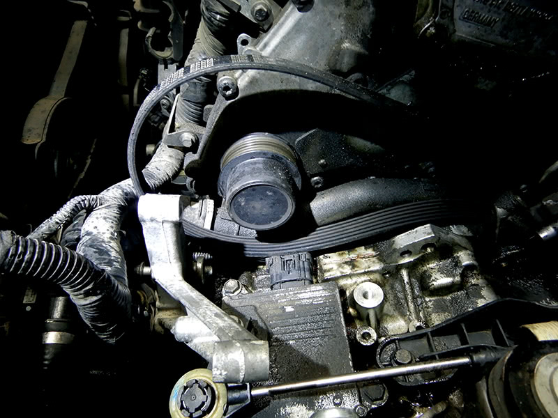
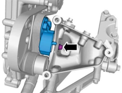
When the bearing in the coupler pulley becomes noisy (7), and/or the pulley won’t turn freely in one direction, it must be replaced before internal engine problems occur to the complete READ assembly or even worse, engine timing chain problems.
When maintaining customers’ vehicles, it is always a good idea to check to see if the drive belt will spin freely in one direction; if not, or it feels tight, you might want to tell your customer it’s time to replace the coupler pulley, drive belt, tensioner, and idler pulley.
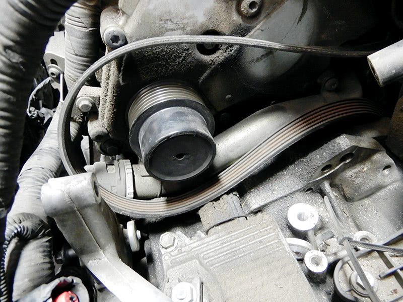
The READ assembly should be checked periodically to prevent damage to the engine. The coupler pulley on the drive belt side should turn one way free; if this pulley becomes locked up, this can damage the engine.
To check this, try to spin the belt on the engine. If the belt spins one direction with less friction, the coupler is OK; when the belt will not spin, it’s time to replace the coupler and any other parts that are damaged or need to be replaced.
Replacing coupler pulley, belt, tensioner, and idler pulley at READ assembly
Remove the air filter housing, disconnecting the air mass meter. Disconnect the battery; always disconnect the negative cable first. Disconnect the electrical connector from the computer that sits on top of air filter housing. Pull up on the housing and remove it. Remove the plastic hose down to the throttle housing from the air filter assembly. Remove the battery tray and its three 8 mm bolts and set aside.
You will need to evacuate the air conditioning system. Remove the bracket that holds the power steering reservoir from the back side of the compressor. There are two 13 mm nuts and one bolt. Disconnect the hard lines going to the air conditioning compressor. Disconnect the electrical connectors at the compressor. Remove the T25 Torx screw at the bracket that holds the air conditioning line. Now you can move the air conditioning lines out of the way.
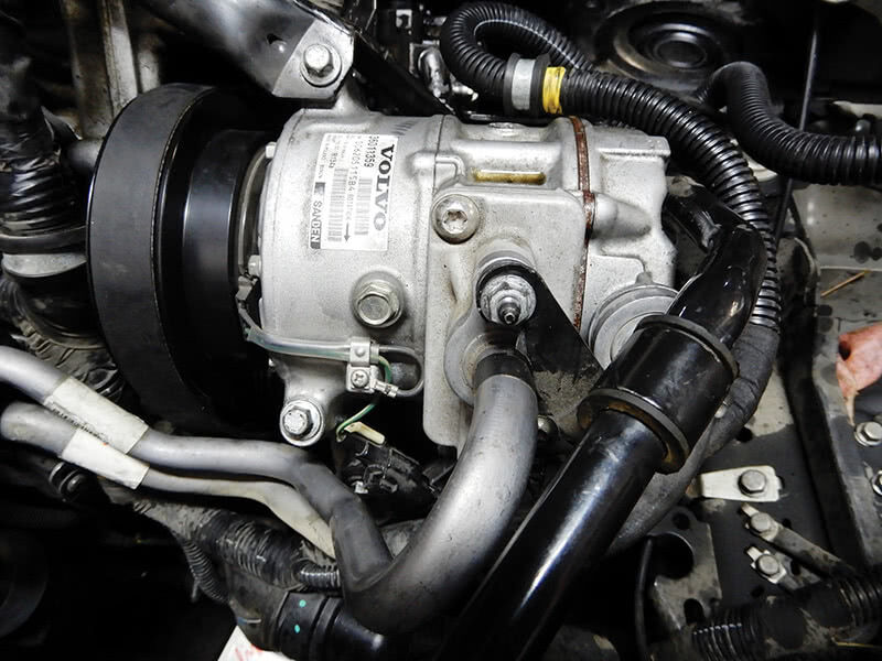
Remove the brackets at the air conditioning compressor. Remove the power steering hose at the pump if so equipped. Depending on the model and year you might have a pump or not. In this case remove the power steering hose and set it out of the way.
At the drive belt tensioner, using a 19 mm wrench, release the tension. Use a 3 mm pin and insert it at the tensioner to lock the tensioner into position. The belt will now be free. Now that the brackets to the air conditioning are removed, remove the three bolts that hold on the air conditioning compressor and wiggle the compressor out of the engine bracket. Tape up the compressor line connections so dirt and moisture don’t get into the compressor.
After the air conditioning compressor is out of the way, there is a bolt that holds the drive belt tensioner into place. Remove this bolt and remove the tensioner. Now the bracket that holds the air conditioning compressor needs to be removed. Four bolts will need to be removed and set the bracket out of the way.
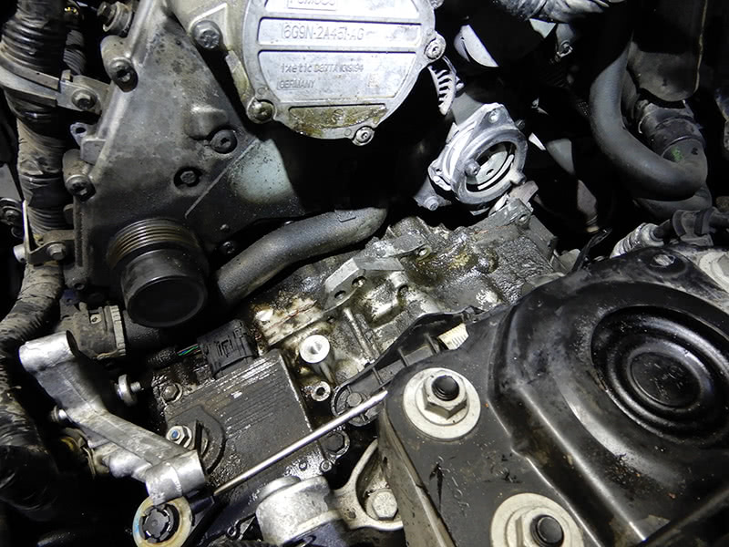
After the lines have been disconnected, use a T25 Torx bit, quarter-inch drive, on a long extension to remove the screws at the pump pulley.
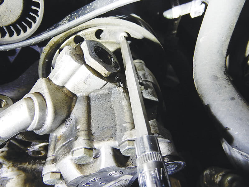
Once the screws are removed, remove the bracket at the back of the pump and two bolts that hold the pump in place. Push in on the spring behind the power steering pump and remove from the vehicle. Engines with no power steering pump will be a little bit easier to deal with.
Now that the power steering pump is out of the way and the tensioner is removed from the engine, you can now remove the bracket that the air conditioning compressor sat in.
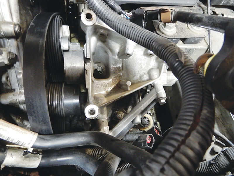
Now remove the auxiliary bracket under the air conditioning compressor, depending which model will determine the number of bolts that need to be removed. After removal of the bolts, you can now remove the bracket and set aside.
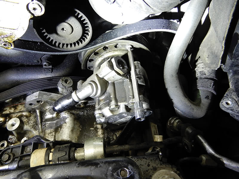
Now that the bracket is out of the way, we can see the coupler pulley. To remove the cap that covers the release bolt, drill a small hole into the cap, insert a small screwdriver and pop out the cover. This cover will be replaced when installing the new coupler pulley.
To remove the coupler pulley, you will need special tools 9995760 and 9512926. Remove the coupler pulley and pop out the seal with a screwdriver or an awl. Install a new seal using special tool 9997265. Install the new coupler pulley and using special tools 9995760 and 9512926 to tighten down to 60 Nm.
Install the cap over the end of the pulley. Now you can start putting everything back together. Set the new drive belt into place around the coupler pulley. Install the auxiliary bracket and tighten all bolts.
Install the power steering pump back into place, making sure to wrap the drive belt around pulley for the power steering pump. Set the pump into place and adjust the spring assembly into power steering pulley. If you don’t install the drive belt at this time, the pump will have to come back off, so don’t forget.
Once the pump is into place, secure the two bolts that hold the pump on. Install the T25 Torx bolts at the pump pulley to spring assembly for the water pump and tighten.
Install new idler pulley, and slide the tensioner into place at the auxiliary bracket for the air conditioning compressor. Leave the pin in the tensioner until the A/C compressor is secure.
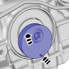
Install the air conditioning compressor and secure the bolts. Install the brackets at the top of the compressor. Connect the A/C hard lines, making sure to replace the A/C o-rings. Tighten down. Secure the A/C hoses at the bracket with the T25 Torx fasteners. Connect the electrical connectors at the A/C compressor. Install the power steering hoses and tighten. Remove the pin from the tensioner. The drive belt should be tight and spin freely in one direction, counterclockwise.
Evacuate the A/C system, vacuum and charge the system with the correct amount of refrigerant.
Install the battery box, then install the battery. Set the air filter box into place, connecting the hose at the throttle housing. If equipped with an ECM on top of the air filter housing, secure and connect the electrical connectors.
Tighten down the battery terminals, starting with positive first, then negative. Start the vehicle and make sure everything is operating correctly. Test drive the vehicle making sure the air conditioning is nice and cold.
Doing this job ensures there will be no premature problems with the READ assembly.
The Rear End Auxiliary Drive (READ)
Let’s talk about how to rebuild or repair this component. Let’s say you have a major noise, possibly a grinding sound from the READ assembly, and you know it will need to come apart. First thing is to make sure you have all the tools to do this job. Second, this is a time-consuming repair and needs to done by an experienced technician.
To do this job, you will need to remove the intake manifold, which is not too hard to do. Remove the air cleaner box assembly and disconnect the hose at the throttle body, and remove together.
Remove the two bolts at the bottom by the throttle housing that holds the intake to the block. Disconnect all electrical connectors and hoses. At the top, remove the electrical connector for the fuel pressure sensor and the coolant hose at the middle of the manifold.
Remove the seven bolts that hold the manifold to the block and remove the intake manifold from the vehicle.
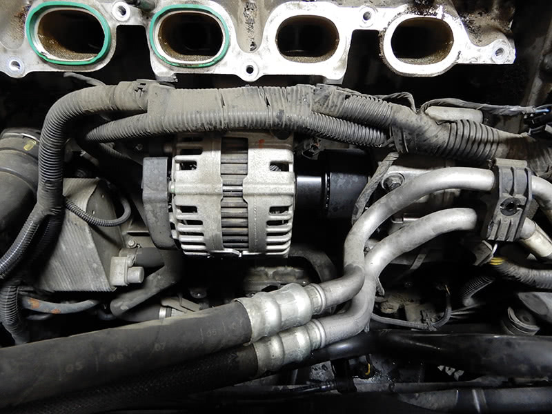
Now the alternator will need to be removed. Take out the four bolts and two electrical connectors and remove the alternator with the small belt that connects alternator to the READ assembly.
Now let’s go back to other side – the timing chain side. Remove the battery, battery box, and the air conditioning compressor and brackets, as we previously explained. Once everything is out of the way, remove the coupler pulley at the drive belt side.
You will need to remove the timing chain to remove the READ assembly for rebuilding. First, use tool 9997257 at the front of the engine at the crankshaft; turn the tool to lock in position.
Use tool number 9997261 to lock the camshafts into position at the front of the engine.
Remove the coolant pipe at the bottom of the timing cover. Remove the twenty bolts around the timing cover and the two in the center and pop off the timing cover and set it aside.
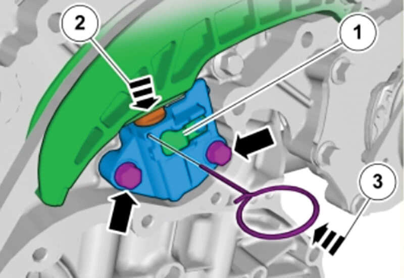
Now we need to remove the inner timing cover. First we need to remove the timing chain tensioner. Raise the tensioner’s lock plate (1) and press the tensioner together (2). Use a 2 mm drill bit and insert it into the tensioner hole to hold the tensioner in position for removal (3).
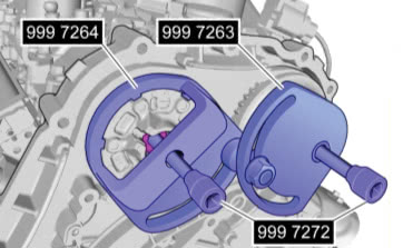
Remove the timing chain from the gear sprockets. Use tools 9997264, 9997263, and 9997272 to remove the gear sprockets — both intake and exhaust.
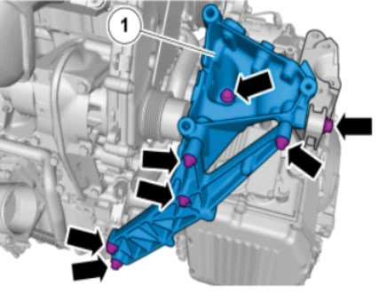
Remove the two bolts that hold on the inner timing cover and remove the cover. Now that everything is removed, we can remove the READ assembly from the engine. Seven bolts hold this unit in place. Use tool 9995670 to release the unit from the engine block.
The READ assembly unit is unique to each engine; when removing it, if either the READ unit or the block is damaged, both will need to be replaced.
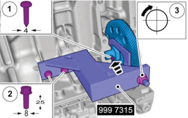
To remove the gear still installed at the block, you will need to use tool 9997315 to press out of the block; you will need to replace the set pin when installing back into the block.
After the READ assembly has been rebuilt, now we can install the unit to the block. Install the gear back into the block, and install the new set pin with punch, tool 9997316. Use liquid gasket part number 1161771 on the surface of the READ assembly and install on the block.
Install six bolts finger tight, the bottom left bolt, and thread sealant, and install finger tight. Tighten down the bolts using this sequence.
Now that the unit is secured to the block, we can install the timing inner cover. Use a new gasket and set the inner timing cover into place with two bolts and tighten down to 17 Nm. Install the timing gear pulleys. This would be a good time to replace the timing chain, guides, and tensioner.
Once the new guides and chain are in place, install the tensioner and remove the pin so the tensioner expands. Remove the tool at the camshaft and crankshaft and spin the engine around a couple of times to make sure everything is smooth and in time correctly.
Remove the seal from the outer timing cover. Turn the two 9 mm allen screws at the front of the cover a couple of turns. Install the cover using tools 9997267 and 9997266 to align the cover to the engine. Install three bolts, one at the top, one at bottom, and one to the right of the cover and adjust finger tight; with tools in place, align the gasket and cover.
Install three bolts at the middle of the cover, and then install the rest of the bolts. Torque down to 17 Nm. Turn the two 9 mm studs in until they make contact.
Install the bottom coolant pipe and vacuum pump. Install the idler pulley for the drive belt, install the bracket for the air conditioning compressor, and install all components on the timing chain side as discussed earlier in article.
Position the alternator side install pulley at the READ assembly and, using tool 9997258 to hold the pulley, tighten the center bolt and torque to 44 Nm. Install the coupler belt. Slide the alternator into the belt, and make sure the two dowels between the block and the alternator are aligned properly.
Install the four bolts and tighten down. Install the electrical connectors to the alternator. Set the intake manifold back into place, using a new gasket and install the bolts and tighten down. Install the two bolts at the bottom of the manifold, and attach all electrical connectors and hoses.
Set the air filter assembly into place securing the hose at the throttle housing.
Servicing the READ assembly is not a simple task. But it’s good to know what’s involved when the occasion arises.


0 Comments