


An oil leak or burning smell might indicate a leak from the front engine cover. Here’s the procedure for resealing front engine covers.
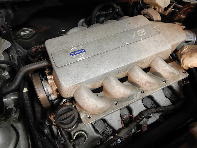
You might have a customer that comes in complaining about an oil leak or maybe a burning smell. On the Volvo XC90 V8, the front engine cover might be leaking and oil could be all over the under chassis. In this article, we will go through the procedure of resealing the front engine cover.
First thing you might want to do is steam clean the engine to help clean it up for the procedure. This is a big job, so make sure to organize all of the parts during disassembly. The vehicle will need to go onto a hoist when doing this job. Disconnect the battery in the back of the vehicle.
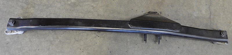
Remove the four bolts, two on each side, near the strut towers, for the top mount cross bar. Remove the bolt at the engine mount, and set the cross bar out of the way.
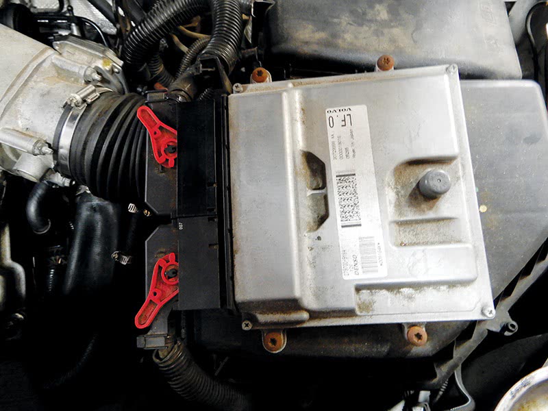
Remove the cover over the ECM and the air filter housing by pulling straight up. Disconnect the ECM electrical connectors, being careful not to break the connectors when removing them. Disconnect the air mass meter connector. Remove the two bolts that hold down the fresh air intake to air filter housing and remove.
Loosen the hose clamp at the hose that connects the air mass meter to the throttle housing and remove air filter housing by pulling up. Set the filter housing out of the way. Remove the upper engine cover and both covers over valve covers. Pull out the dipstick so not to damage it.
Remove the four bolts that hold down the top mount and set aside. Raise the vehicle up and drain the oil and coolant. While the the vehicle is up, remove the protective cover and the six bolts that hold it in place. Once bolts are removed, lift up and pull out.
Lower vehicle and, on the front side of the engine, you will want to remove the expansion tank and power steering reservoir. If possible, remove all the fluid from the power steering reservoir so as not to make a mess.
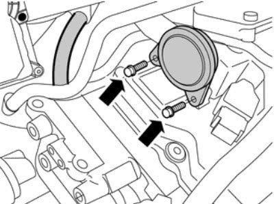
Remove the cover over the power steering pump, two bolts. Lift the cover from the top of the pump. Disconnect the ground cable between the engine block and chassis. Remove the oil line to the steering pump and plug the pump to prevent leakage.
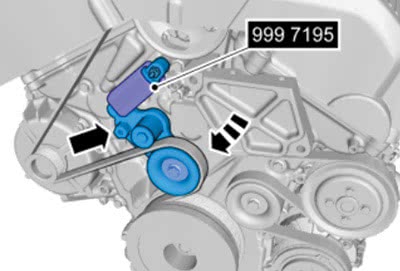
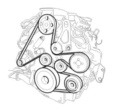
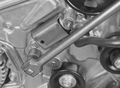
Now you will be able to expose the auxiliary belt tensioner. Using a long ½ inch breaker bar and socket, pull from front of the vehicle, clockwise to 230 Nm. Pulling back should take about 20 seconds before inserting tool number 9997195 to lock in place. Now you will be able to remove the auxiliary drive belt.
Before removing the drive belt, it’s a good idea to take a photo of the belt routing.
Now that the belt is removed, remove the connector at the top of the engine at the intake manifold for the pressure and temperature sensor, and also remove the two vacuum hoses to the check valve and distribution damper.
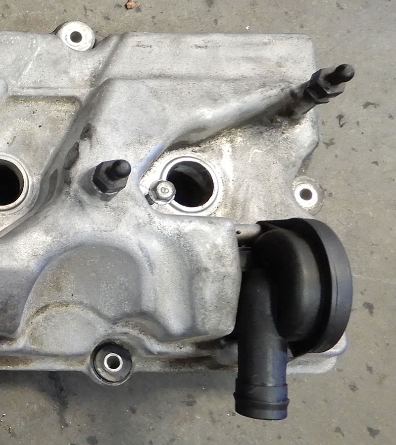
Remove the brake vacuum hose near throttle housing. Remove the hose at the throttle body from air mass meter. Remove the two nuts and screws that hold the throttle housing to the manifold. Now you will be able to disconnect the hose to the coolant pipe and throttle body. Remove the two bolts that connect the non-return valve for crankcase ventilation to the valve cover near the firewall. Disconnect the vacuum hose at the manifold.
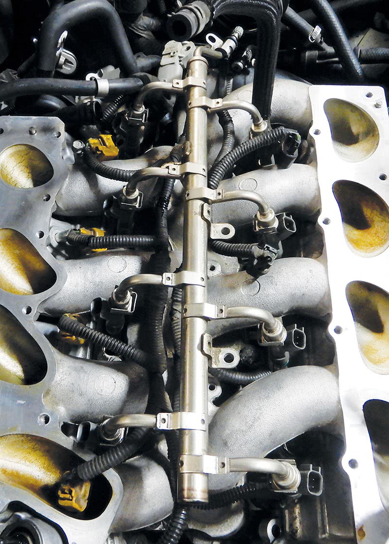
Remove the 21 bolts that hold the top intake manifold in place, lift up manifold and remove the two bolts that hold the coolant manifold to the bottom of the intake manifold. This will make the job a little bit easier, instead of disconnecting the coolant hose. If the coolant hoses are damaged, be sure to replace them when reassembling. Now you can remove the fuel rail, making sure to release the pressure. Remove the ventilation hose between the two valve covers, two hose clamps. There are three bolts that secure the fuel rail that need to come out, and the two at the fuel pressure sensor. Disconnect the main supply and return hose from the rail. Lift up and remove the fuel rail.
Now for the lower intake manifold; remove the 12 bolts that hold it in place. Remove it from vehicle. Remove the hose from the power steering pump to the reservoir cap at pump. Remove the three bolts that hold pump in place; looking through the pulley you will see the three bolts.
Next will be to remove the valve covers. First disconnect the electrical connectors at the coils. On the valve cover near the firewall, remove the fuel lines and remove the bolts at the bracket. Set the lines out of the way. Remove the bolts that hold down the ignition coils and remove the coils.
The valve cover is close to the radiator, so remove the cam sensor electrical connector and harness and push it down out of the way. Remove the seven bolts that hold the valve cover on and remove the valve cover.
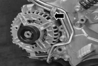
At the valve cover, near the firewall, you will need to remove the bolt near the alternator that holds the fuel lines in place. Disconnect the cam sensor and ignition coils and set the harness out of the way. Remove the bolts from the valve cover and remove from engine.
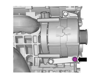
Now for the front engine cover, you will need to remove the two idler pulleys for the drive belt. Also remove the front pulley at the water pump, four bolts, and set aside. Remove the front bolt at the bottom of alternator that is connected to the front cover.
Raise vehicle up on a hoist and remove the right front tire. Remove the inner plastic fender; this will help to get to front cover. Now you will want to remove the front crank pulley. Using tool number 9997196, secure it into place and remove the front bolt from the pulley. Use puller 9997198 to remove the pulley from the crankshaft. Now the front engine cover is exposed and ready to remove.
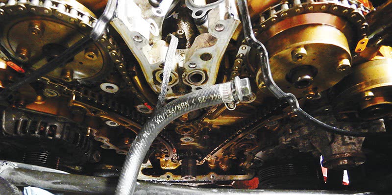
You will need to remove engine mount that is connected near front engine pulley. Using a jack and a block of wood, set it under the oil pan and jack up. Remove bolts at the front mount and remove the engine mount. Now remove the 24 bolts that hold the front engine cover on. Once all the bolts are out, remove front engine cover from engine. Check timing chain, guides and tensioner to make sure all are in good working condition.
Clean the front cover and engine block, making sure not to damage the surface. Once the cover and engine block are completely clean, you can now install the cover back onto the engine block. Using sealant part number 30757050, add sealant to the cover. Do not leave sealant on the cover for longer than five minutes. Install the front cover onto the engine block. Insert the 24 bolts into the cover and torque down to 24 Nm.
Install the new idler pulleys for the drive belt and tighten down. Do the same with the water pump pulley.
Install the bolt you took out of the alternator to front engine cover and tighten. Install a new seal at the crankshaft; use tool number 9997197 with the front crankshaft bolt and tighten down until the tool bottoms out. Remove the bolt and tool, and install the front crankshaft pulley; using special tool number 9997198 screw into crankshaft. Use the counter hold tool number 9997196 that connects to the front pulley, now screw in the center bolt at tool 9997197 until the pulley is completely installed. Remove the tools and tighten down the center bolt for the crankshaft pulley.
Now for the valve covers, first make sure all surfaces are clean and free of debris. Install a new valve cover gasket onto the valve cover. Install the valve cover onto the engine starting with valve cover closest to the firewall. Make sure nothing is in between the valve cover and engine. Install the seven bolts and torque down to 10 Nm. Install the other valve cover and secure in the same manner. Secure the bracket for the wire harness that connects to the bolt for the valve cover.
Install the ignition coils and tighten down. Run the ignition coil electrical harness to each coil and connect each electrical connector to its coil. If the connector is broken, this would be the time to replace it and the terminal. On the valve cover near the firewall, add the bracket and fuel lines, connect the fuel lines and secure them to the valve cover. Install the bolt at the front engine cover that holds down the hard fuel lines.
Install the electrical connectors for the vacuum valves at the front side of the valve cover near the firewall, and connect the camshaft sensor electrical connector on both sides.
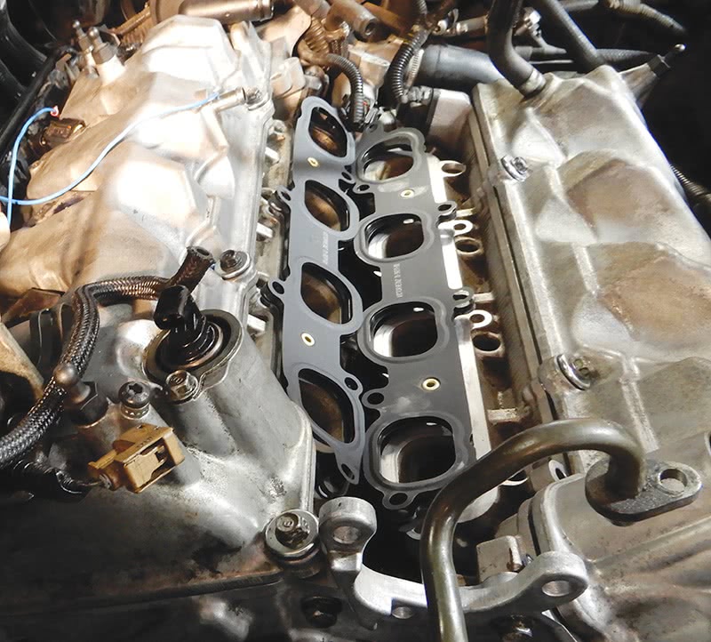
Install new lower intake manifold gaskets and set the lower intake manifold into place. Install the 12 bolts that secure the manifold into place and torque down. Install fuel rail with injectors, lubricate the o-rings at the injectors and fit the fuel rail into place. Install the three bolts that hold down the fuel rail and tighten. Tighten the two screws that hold the fuel pressure sensor in place. Connect the fuel pressure hose to the fuel rail and tighten.
Add the hose between the top intake manifold and the crankcase ventilation non-return valve and tighten down the hose clamp. This makes it much easier to install the return valve into the valve cover after the top manifold is in place.
Set the power steering pump into place and tighten down the three bolts that secure it. Connect the power steering pressure line to the pump, and use a new o-ring.
With new gaskets in place, install the top intake manifold, install two bolts that hold the coolant manifold to bottom of the intake manifold, be sure to use a new rubber gasket. Make sure to connect the vacuum hoses. Install the 21 bolts that hold the intake manifold in place and torque down. Now slide the return valve into the valve cover and secure the two bolts that hold it in place. Connect the pressure sensor and temperature sensor electrical connectors at the intake manifold.
Install the top engine mount. Install the throttle housing with a new gasket and install the two nuts and the two bolts and tighten down. Connect the two coolant hoses and tighten the clamps. Connect the throttle housing electrical connector.
Set the air filter housing into place, and connect the hose from the throttle housing to the air mass meter at the filter housing and tighten the clamps. Connect electrical connectors to the ECM and air mass meter.
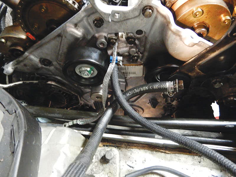
On the front of the engine, you will need to add the auxiliary belt tensioner. Install the center bolt and the top nut for the tensioning and damping element and tighten. Connect the ground strap from the body to engine and also connect the expansion tank hose to the engine. Route the auxiliary drive belt around the pulleys accordingly. Use tool number 9997279 at the center bolt of the tensioner. Using a breaker bar, turn clockwise to 230 Nm and remove tool number 9997195 from the tensioner and release the breaker bar. Make sure the belt is riding correctly on each pulley and tension is good.
Set the expansion tank and power steering reservoir in place. Connect the power steering delivery hose to the power steering pump and to the reservoir and tighten the two clamps. Secure the bracket at the front of the engine for the power steering pressure hose. Connect the coolant hoses at the expansion tank and tighten the clamps.
Install the cover over the power steering pump and covers over the valve covers. Raise the vehicle up and install the inner plastic fender, along with the front tire. Raise the vehicle completely up and install the skid plate, six bolts hold it in place. Install the protective cover on the subframe, six bolts hold it in place.
Lower the vehicle down, install the fresh air duct for the air filter housing and secure the two bolts that hold it down. Set the top cover over the engine into place and push down to secure. Put the cover over the ECM and snap into place.
Add power steering fluid, raise the vehicle up just so the front tires are off the ground and turn the steering wheel back and forth, without starting the vehicle, to remove all air from the system. Continue to do so until bubbles are completely gone. Fill with coolant and top off as needed. Check the engine oil and top off if needed.
Connect the battery and start the vehicle. Check the power steering fluid and add if needed. You might get a few air bubbles in the power steering. If so, shut the vehicle off and turn the steering wheel back and forth until air bubbles are gone again. Repeat if necessary.
Check the vehicle for any leaks, test drive and check again.


0 Comments