
Yes, there is a lot of wire in a car, but did you ever wonder just how much wire?
Well, based on various estimates, the typical mid-size car can have up to three miles of wiring. Now, three miles of anything weighs a lot and takes up a lot of space. And installing all the wiring in a car also takes a lot of time and money. With the apparently unending growth in the use of electronic components in modern vehicles, even more wiring will be necessary in the future.
Anything that reduces the amount of wiring in a vehicle saves space, weight, and money. That’s why BMW and other carmakers are jumping on the “CAN” Bus. CAN stands for “Computer Area Network” and “bus” is an electronics term for a system that links multiple points or devices together with a common connection.
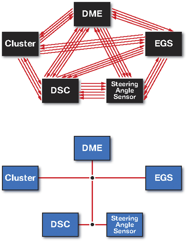
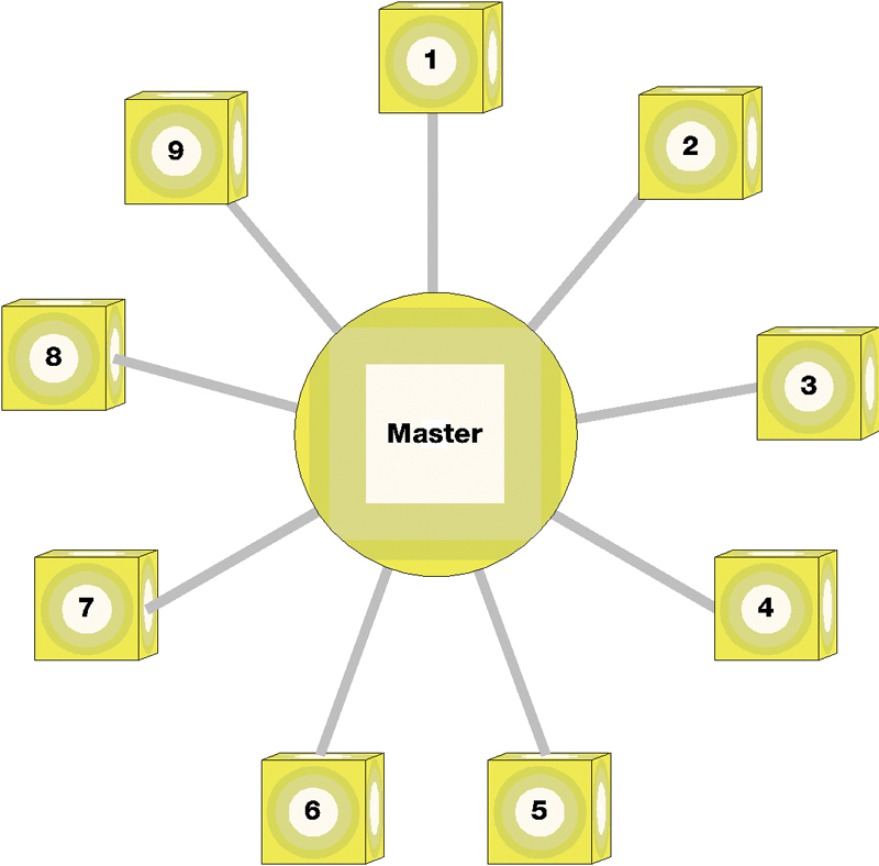
Before CAN bus, every component was wired to every other component individually (above). With CAN bus, one set of wires connects everything.
CAN bus technology was developed in the late 1980s by Intel™ and Robert Bosch. The companies realized that unless there was a way to reduce the amount of wiring needed in a modern vehicle, the automotive industry was on the verge of an unmanageable wiring problem.
On a BMW, the ECU (Engine Control Unit) requires inputs for engine speed, air temperature, coolant temperature, throttle position, road speed, etc. to properly manage spark timing and fuel flow for optimal power and fuel economy while also minimizing emissions. In the pre-CAN bus days, each sensor had to be connected to the ECU with a separate wire, and the signals from each sensor differed by duty cycle, frequency, range, etc. So, the resulting connection to the computer was a thick wiring harness that had to fit in the limited space available inside the car.
With a CAN bus, that thick harness is gone, replaced by just two copper wires twisted together. One wire is the called the “CAN-high,” the other is “CAN-low.” Each wire transmits an opposing signal through the system at the same time. The opposing signals virtually eliminate the effects of outside electrical interference on signals sent over the CAN bus.
Both wires are attached to every component in the system. “Node” is the generic name for any device on a CAN bus. In automotive use, the nodes are usually “transmitters” and “receivers.” The transmitter nodes are the various sensors and other devices that provide input data to the computer system. The receiver nodes are the actuators that receive and respond to data.
BMW first used a CAN bus on the 1993 740i/iL as a data link between the DME (Digital Motor Electronics module) and the EGS (electronic transmission control), and started using it for scan tool communications on the E70 and R56. Since then, BMW has expanded its use of the technology across its entire vehicle lineup. The early BMW CAN bus installations used shielded cable, but since MY 2000, the system uses two copper wires twisted together.
On current BMWs, the CAN bus typically links the:
• Engine controller (DME)
• Electronic transmission controller (EGS)
• Dynamic stability controller (DSC)
• Instrument Cluster (KOMBI)
• Lateral acceleration sensor
BMW also uses K-bus and MOST-bus technology on its later models. The K-bus or Body Bus is a “low speed” circuit used to connect components inside the vehicle. The MOST-bus is an extremely fast fiber optics circuit used to transmit visual or audio signals.
Benefits
BMW is certainly not alone in riding the CAN bus. The technology has become the virtual standard for under-hood and under-car communication among electronic devices on almost every new vehicle from every manufacturer in the world. CAN bus technology is also being used in many non-automotive applications, wherever sophisticated electronic components must communicate with each other in a system. According to various electronic industry estimates, hundreds of millions of devices or systems using a CAN bus are manufactured every year.
It is easy to see why BMW has moved quickly to adopt the system, because CAN bus technology:
- Replaces multiple bundles of thick wiring harnesses with just two twisted wires, saving weight, space, and installation cost.
- Not only reduces the wiring needed, but also reduces the number of components in the system because messages from any component are shared throughout the system. For example, the ambient air temperature sensor can send data to both the ECU and the climate control system, instead of requiring two temperature sensors, one for the ECU and one for the climate control.
- Is energy efficient. The bus operates on 2.5 volts and goes into “sleep mode” when no messages are being transmitted. The system immediately “wakes up” when a message is sent.
- With fewer wires and components, is more reliable in the harsh under-hood and under-car environments.
- Is extremely accurate. The system has virtually no transmission failures or errors.
- Makes troubleshooting easier. The system can identify any node that is not performing properly and transmit a failure code for that component.
- Is easier to modify, adapt, or expand to meet different vehicle requirements.
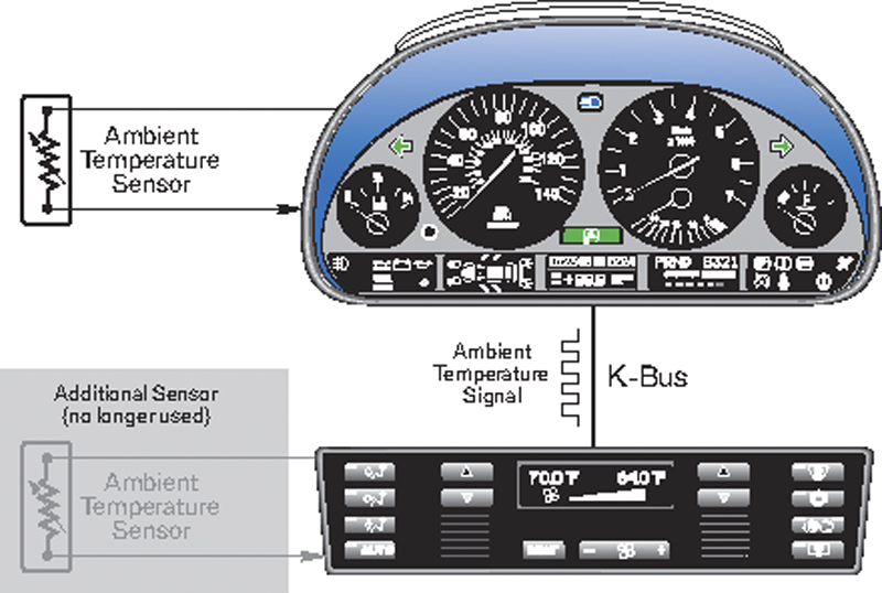
BMW uses a different bus, the K-bus or Body bus, for low speed data transmission inside the vehicle.
Different from multiplexing
The CAN bus concept is similar to “multiplexing” with one significant difference. In a multiplex system, each transmitter and receiver has a unique address. Each message is sent directly from one unit to another unit. The message bypasses all other components on the system.
With a CAN bus, all nodes can send and receive data equally. In theory, any given node could communicate with all of the other nodes at any time. However, the programming controlling the CAN bus labels each message sent out with a unique identifier code. As the message is received, each component on the system “opens” or “reads” the message and immediately looks for the identifier code. A component will process only the messages that have the correct ID code for the component. All other messages are ignored. The use of identifier codes, instead of unique address, is one reason why CAN bus systems can be easily modified and expanded.

Morse code is a “human” version of the electronic bit. In between sending a dot or dash (switch on) there is no signal (switch off).
The identifier code also gives the message its priority. When a component receives two messages at the same time, the node will process the higher priority message first, ignoring the lower priority message. Within the CAN bus system, no messages are ever lost. The lower priority message is stored and retransmitted later, after the high priority message has been processed. In addition to priority, the identifier code also tells the CAN bus how fast to send the message. For example, the signal to activate the antilock brake system (ABS) would be sent at the fastest possible speed through the system, while an adjustment to the climate control system would be sent a at slower speed.
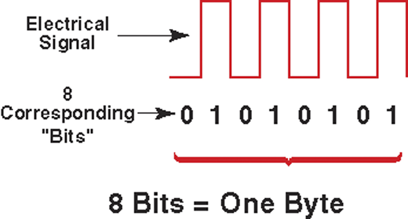
Of course, to a CAN bus, later and slower are measured in milliseconds. To humans, high and low priority messages are processed at the same time and there is no such thing as slower, but within the CAN bus, there is a later and slower. In a BMW CAN bus, data is transmitted at speeds up to 500K (500,000) bits per second (bps), which is an extremely fast rate for a “hard wire” system. “Bit” is the electronics term or abbreviation for “binary digit” which is either a 0 or a 1. Eight bits make up a “byte” and a series of “bytes” forms the digital message or signal that is transmitted along the CAN bus.
Troubleshooting
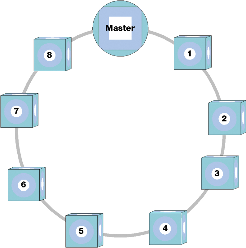
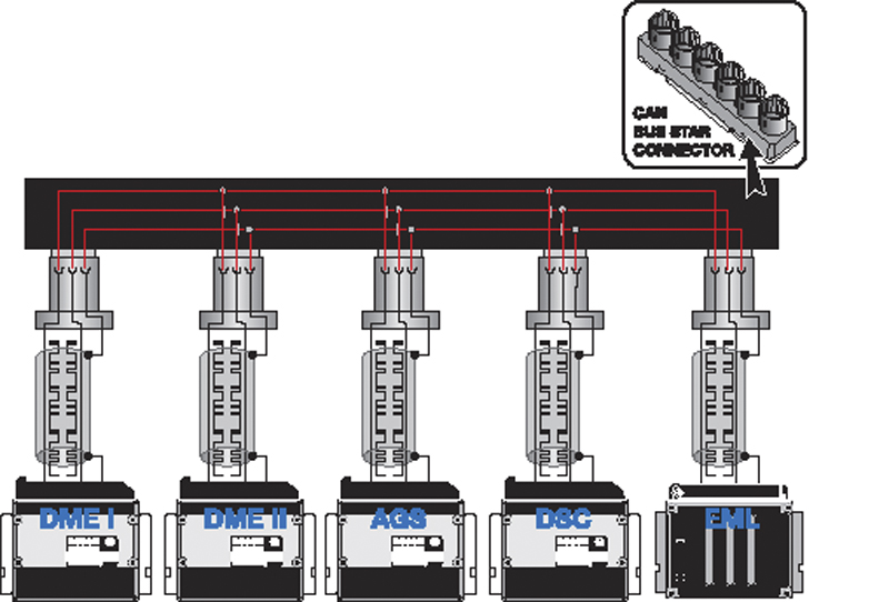
BMW uses a “Tree” or “Linear” arrangement for its CAN bus applications. Two other setups, the Ring and the Star, are used with the K-Bus and MOST-bus applications. In a Tree arrangement, the twisted wires are the “trunk” and each component on the circuit is a branch. The ability to easily add or delete components gives the CAN bus its flexibility for different applications.
The CAN bus is normally a very reliable system, but problems can occur. If there is a CAN bus communications fault that uses the term “Timeout,” this refers to a component that cannot communicate with other units on the system. Each component will attempt to communicate several times. If there is no success after multiple attempts, the system will store a “Timeout” or “CAN bus” failure code. The system will self-diagnose to determine if the problem is within the bus or one of the units that cannot receive its messages.
Wiring failure
Before testing the CAN bus, check to make sure that there is normal battery voltage present and that the charging system is operating.
Failure of the CAN bus wiring can be caused by a break in the wire, shorts to battery voltage or ground, the two wires becoming shorted to each other, or a bad connection with one of the units on the system.
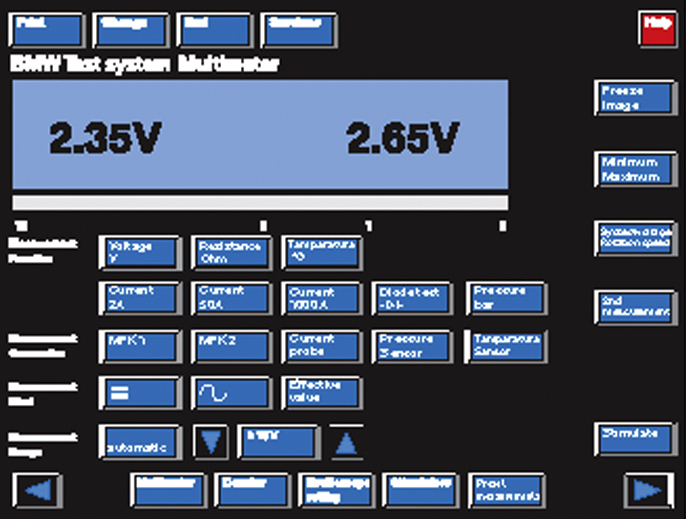
Test for voltage drop and continuity among the components. The CAN bus should show an average of 2.5V on both the CAN-high and CAN-low wires. However, the presence of 2.5 volts does not eliminate the possibility of a fault in the bus, it only indicates that there is adequate voltage for proper operation.
CAN bus wiring is tested like any other automotive wiring. Check the twisted wires first. Then test for continuity between the connections of the different components, with all components disconnected from a power source.
Resistor failure
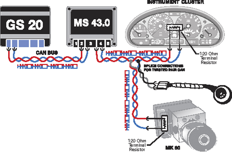
Terminal resistors are used in the CAN bus circuit to establish the correct impedance to ensure fault-free communication. A 120 Ohm resistor is installed in two control units of the CAN between CAN-H and CAN-L. Because the CAN is a parallel circuit, the effective resistance of the complete circuit is 60 Ohms. On some vehicles there is a jumper wire that connects the two parallel branches together, others have an internal connection at the instrument cluster.
The resistance is measured by connecting the appropriate adapter to any of the modules on the CAN and measuring the resistance between CAN-Low and CAN-High. The resistance should be 60 Ohms. The CAN bus is very stable and can continue to communicate if the resistance on the CAN bus is not completely correct; however, sporadic communication faults will occur.
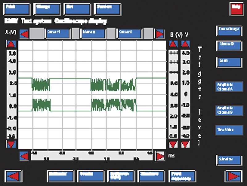
The top trace shows the 2.5V base line for the CAN-low wire. The voltage is “pulled down” during data transmission. The lower trace shows the 2.5B base for the CAN-high. Its voltage is “pulled up” during data transmission.
The terminal resistors are located in the ASC/DSC control unit and either the instrument cluster or in the DME. Early 750iL vehicles that used the star connector have a separate external resistor, which connects CAN-H and CAN-L together.
Modules that do not have the terminal resistor can be checked by disconnecting the module and checking the resistance directly between the pins for CAN-H and CAN-L. The value at these control units should be between 10 kOhms and 50 kOhms.
Control unit failure
Each component attached to the CAN bus has its own communications module that allows it to communicate with other nodes on the bus. Failure of a control unit’s communication module normally triggers a fault code in the other units on the bus.
In rare cases, failure of one unit can take down the entire bus. When that happens, every unit will store a fault code. To isolate the defective unit, disconnect units one at a time while monitoring CAN bus readings with an oscilloscope or voltmeter. When the defective unit is disconnected, the faults will only point to communication with that unit and none of the other units.
Interference
Interference is rare, but can happen. Unfortunately, interference problems often resemble shorts or communications failures. The primary causes of interference are a defective alternator or improperly installed aftermarket components. Check the CAN bus operation. If no problems are found with the system, verify that generator operation is normal. Then check for aftermarket devices that have been added to the car. Disconnect each device to see if the interference problem disappears.


0 Comments