

Over the years of hot and cold temperatures, use, and abuse, some of the automatic transmission plastic shifter parts can wear and crack.
Over the years Volvo automatic transmission shifter assemblies and controls have tended to be reliable, tough and relatively problem-free, even when your customers let the dog, and sometimes the kids, abuse them.
But, of course, over the years of hot and cold temperatures, use, and abuse, some of the plastic shifter parts can wear and crack.
Sooner or later you will probably see one of these Volvos come into your shop, sometimes on a tow truck.
Your customer will complain about the shifter not staying in Park and slipping down into the manual (Geartronic) shifting mode.
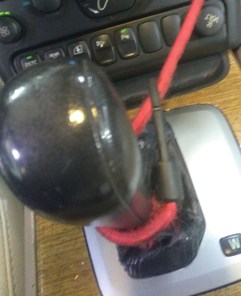
Sometimes your customer will try to temporarily “fix†this condition themselves in some creative ways that will include duct tape or rope in an attempt to keep the car in Drive.
Of course driving like this can cause unsafe driving conditions and the issue needs to be fixed properly.
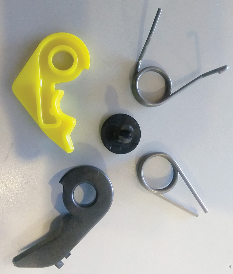
In most cases this condition is caused by a part of the shifter’s rocker arm or claw assembly being cracked or broken.
And in most cases the shifter can be repaired with an inexpensive parts kit that is available from your local Volvo dealer’s parts department. The Volvo part number is 9463559.
Of course before you start ordering parts you should inspect the shift control components and functions to make sure that this is the only problem area.
Start by parking the car on a flat surface and setting the parking brake and chocking the wheels to prevent the car from rolling while you inspect and repair the shifter mechanism. You will need to move the shifter through the gears and into Neutral while removing the shift knob, trim pieces and center console. You don’t want the customer’s car to start rolling down the driveway while you’re working on it!
Some technicians prefer to remove the entire shift assembly to perform repairs but this is not necessary. If you do end up removing the entire shift control assembly, take extra care to mark and make note of the cable positions, and the wire harness routing. Make sure to move the front seats as far to the rear as possible to make it easier to access the panels around the shifter before you disconnect the battery.
Just like any repair that includes working around and removing electrical connections, the best practice is to always disconnect the battery at the negative post before you start.
But first a word about disconnecting the battery on a modern Volvo
Take extra care when replacing and disconnecting the battery on any networked Volvo. There are many reasons to do so besides having to reset the clock.
Here is Volvo’s official procedure
Battery, disconnecting
Note before disconnecting Battery Cables
Warning! The SRS (Supplemental Restraint System) is active for a certain time after the power is cut. Therefore wait three minutes before starting work.
- If the malfunction indicator light in the combined instrument panel is illuminated, the diagnostic trouble codes for the management system must first be read out and remedied before battery power is cut off.
- The ignition should be off for at least five minutes before the battery is disconnected from the car to allow the control modules time to store information.
- If the vehicle is equipped with remote heating, the personal code is reset to the factory value (1-2-3-4) if the battery is disconnected or is discharged.
Caution! Always disconnect the negative battery cable before disconnecting any positive cables.
Note: Before connecting battery cables ensure that no live objects that can short-circuit the battery are under the battery’s protective cover.
Warning! The key must be in position 2. No one must be in the car when the battery is reconnected. This is a safety precaution in case an air bag module activates when the power is connected.
Note after connecting battery cables you must do the following:
- Initiation of the Upper Electronic Module (UEM)
- Initiate the central locking system, interior lighting and sun roof by unlocking the car with the remote control, key or VIDA vehicle communication.
Windows
- Initiate window positions.Â
- Calibrate the passenger compartment fan.
- If the car is equipped with Manual Climate Control (MCC) or standard climate control system, the fan speed must be recalibrated if the battery has been disconnected.
- Ignition on.
- Turn the fan control to Max.
- Turn the fan control to Min.
- The calibration is complete.
Engine
- If the battery was disconnected, the engine may need to run for a few minutes before it runs smoothly.
One thing that is not covered in this list of procedures is that, in some early Volvos (1999-2001) that have the “after blow†program software installed in the Climate Control module (CCM), these systems do not like the battery being disconnected while the CCM is running the “after blow†program.
The “after blow†software was developed to help dry out excess moisture from the car’s evaporator, helping to prevent odors and possible mold growth.
It works by running the interior fan at half speed for 15 minutes, 50 minutes after the car has gone into sleep mode.
Some shops have reported damage to the climate control units by disconnecting the battery during the “after blow,†so don’t take any chances.
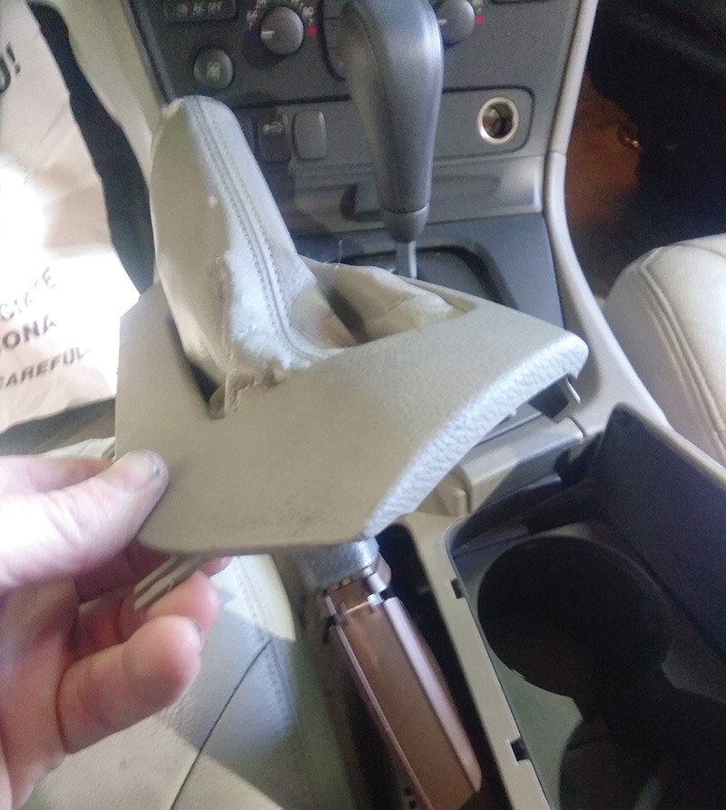
After you disconnect the battery, start disassembly by removing the shift knob.
This step is relatively easy, but can take a bit of brute strength.
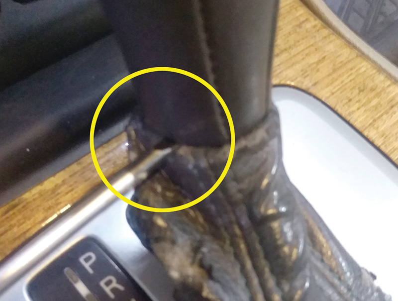
Insert a small screwdriver between the boot and the gear selector lever knob to access the lock bracket. Carefully pry the screwdriver forward so that the lock bracket detaches from the gear selector lever knob.
Now grasp the gear selector lever knob with both hands and pull it straight upwards with a hard jerk. Try not to hit yourself in the face or damage that very expensive rear view mirror assembly or UEM.
Remove the panel (the pen holder) between the dashboard center console and the center console.
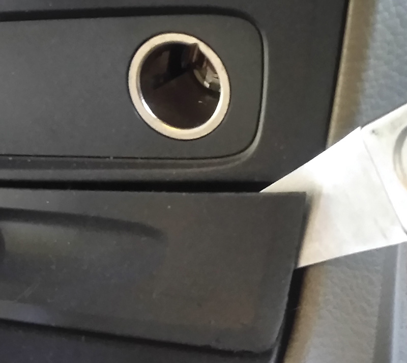
Pry out the panel at both ends. Use a “bone†or similar tool to pull the panel straight out.
Next, use a bone tool to carefully pop out the wood trim plate that surrounds the shift boot and display. There are four catches on the front and rear of the panel that should be depressed while you pull the panel up and out. Be careful not to crack that fake wood trim; it is brittle and is easily damaged.
Next, remove the lower panels on the left and right sides of the center console by removing the twist clips at the rear of the panels and pushing the panels forward to release them.
Remove the two T25 screws at the front of the center console.
Next, open the arm rest and remove the contents and cover at the bottom that hides the two T25 screws, then remove them.
Now pull the panel that has the boot for the parking brake towards the driver’s seat and then pull the boot and cover over the parking brake handle to remove it.
Lift the center console from the rear and reach under it to disconnect the wire harness in the lower rear of the center console.
Carefully lift the center console assembly up and out towards the rear of the vehicle to remove it.
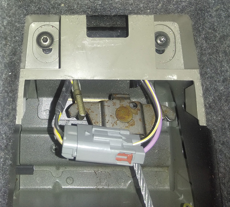
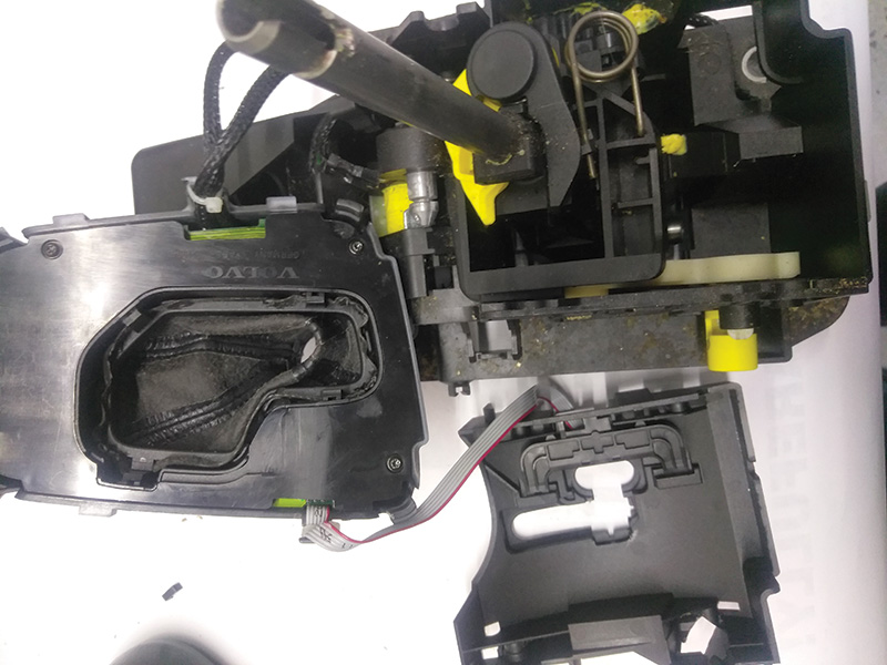
Now with all the panels and center console removed you have the access you need to inspect the shift control assembly.
Check for cracks in the plastic parts and check to see if any of the springs and clips are missing or loose.
Check to make sure that there is no dirt or debris, like loose change or paper clips, jamming the mechanism. Blow out the area with compressed air before disassembling the top of the shift control.
Use a panel tool or small screwdriver to carefully pry under the sides of the top cover at the back while pulling up at the rear. Once it releases, pull it up and over to the side; you can leave the wire harness connected.
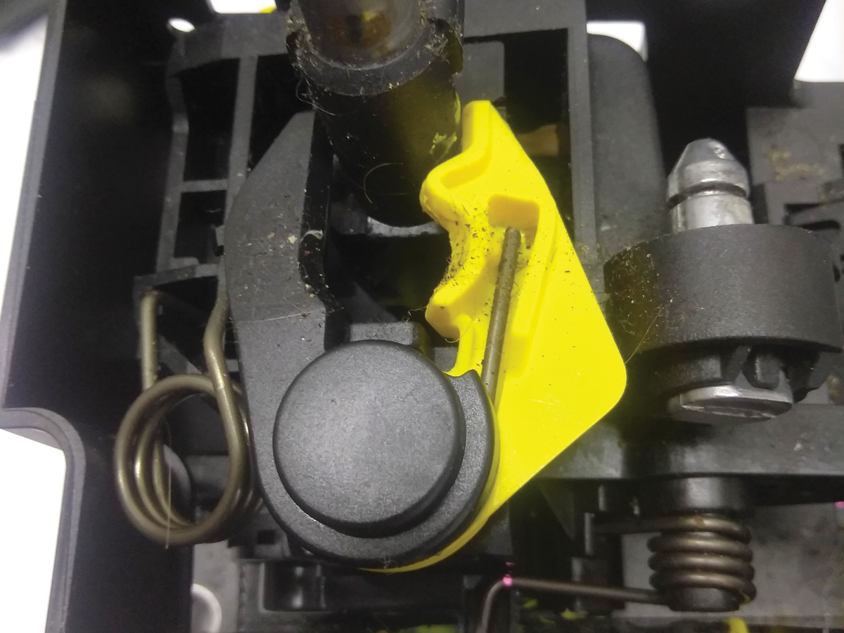
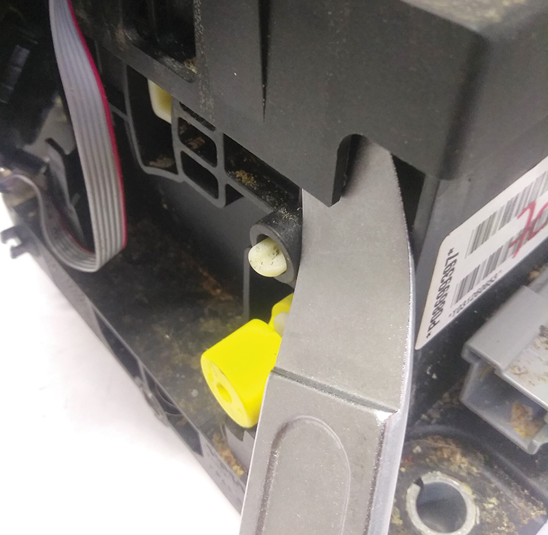
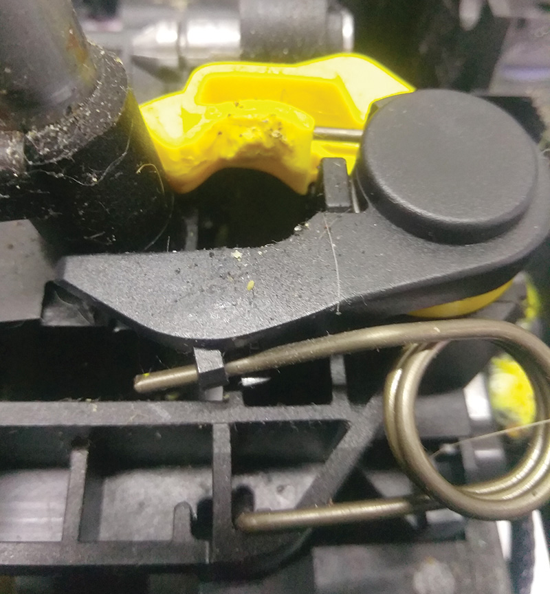
Now you will be able to see the rocker arm in all its broken or cracked glory.
At this point if nothing else is broken but the rocker claw parts (usually the yellow claw part), you can proceed to change out the parts that are included in the parts kit 9463559.
When the parts are removed make sure to blow out any broken bits of plastic and dust to prevent any sticking or jamming in the shift controls.
Reinstall all parts in reverse order and test the function and feel of the shift control.
Reconnect the battery following Volvo’s guidelines, then reset the clock and test drive.
STICKING IDLE AIR CONTROL (IAC) VALVE EARLY S/V40 2000-2004
There are still a fair amount of these first generation S/V 40 series Volvos on the road these days, and you probably still see them coming into your shop for service and repairs.
Volvo officially designated these models as the X40 platform. The first versions of the 40 series cars were seen in Europe starting in 1995. After a few years, and with improvements in the X40 platform cars, they were introduced to the U.S. market in 1999 and sold until 2004 when Volvo introduced the completely redesigned S40, released in 2005. This was part of the P1 platform cars which include the S40, C30, V50, and C70 Volvos.
These cars were manufactured at the Nedcar factory in the Netherlands as part of a joint venture between Volvo and Mitsubishi.
Introduced in the beginning of 2004, the second generation S40 (known as the 2004.5 Volvo S40) had a new design based on the Volvo P1 platform built at the Volvo Cars factory in Ghent, Belgium.
At the same time, the V40 was replaced by the V50, also based on the P1 platform and built in Ghent.
These early S/V 40s have some aging issues, such as deep cracks in the front brake hoses under the spring, worn relays in the Central Electronic Module (CEM) that cause the low beams to lose power, and a few more we have covered in past issues.
The Idle Air Control (IAC) valves on these cars are built well and usually perform properly for a lot of miles.
But if you get one of these early S/V40 series cars in your shop with a stalling issue at idle, even if it’s an intermittent issue, you may have a stuck or sticking idle air control motor.
As with any stalling issue, you should start by interviewing the customer about the symptoms, especially if the symptom is not presenting itself in your shop. Next check the ECU for any stored codes and freeze frame data. A lot of times these cars will not store a code for a sticking IAC.
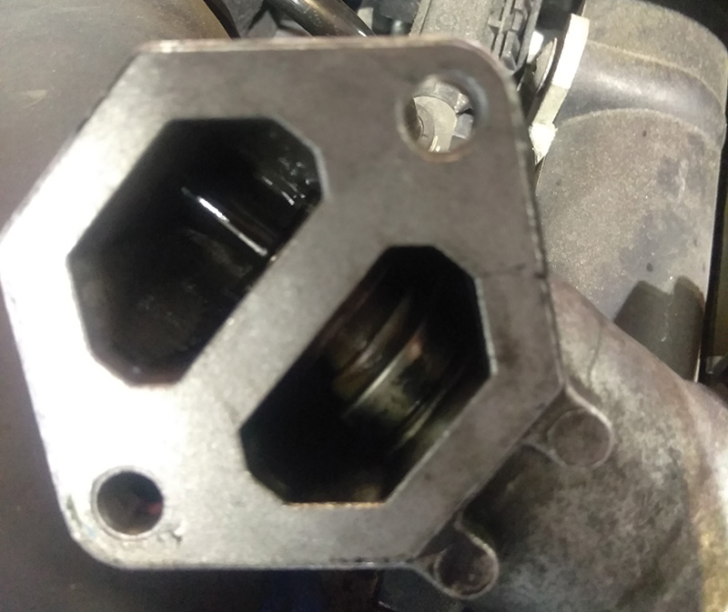
Next, always make checking for intake air leaks part of your test procedure; using a smoke tester is a great way to do this. If there are no leaks in the intake and no other smoking guns, you should remove the IAC valve and test it. If you have VIDA you can command the valve to operate in the Vehicle Communication tab.
Or you can bench test the valve by applying power and ground directly to the pins on the valve.
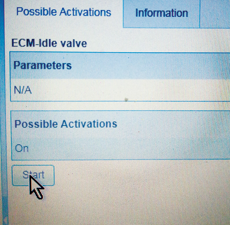
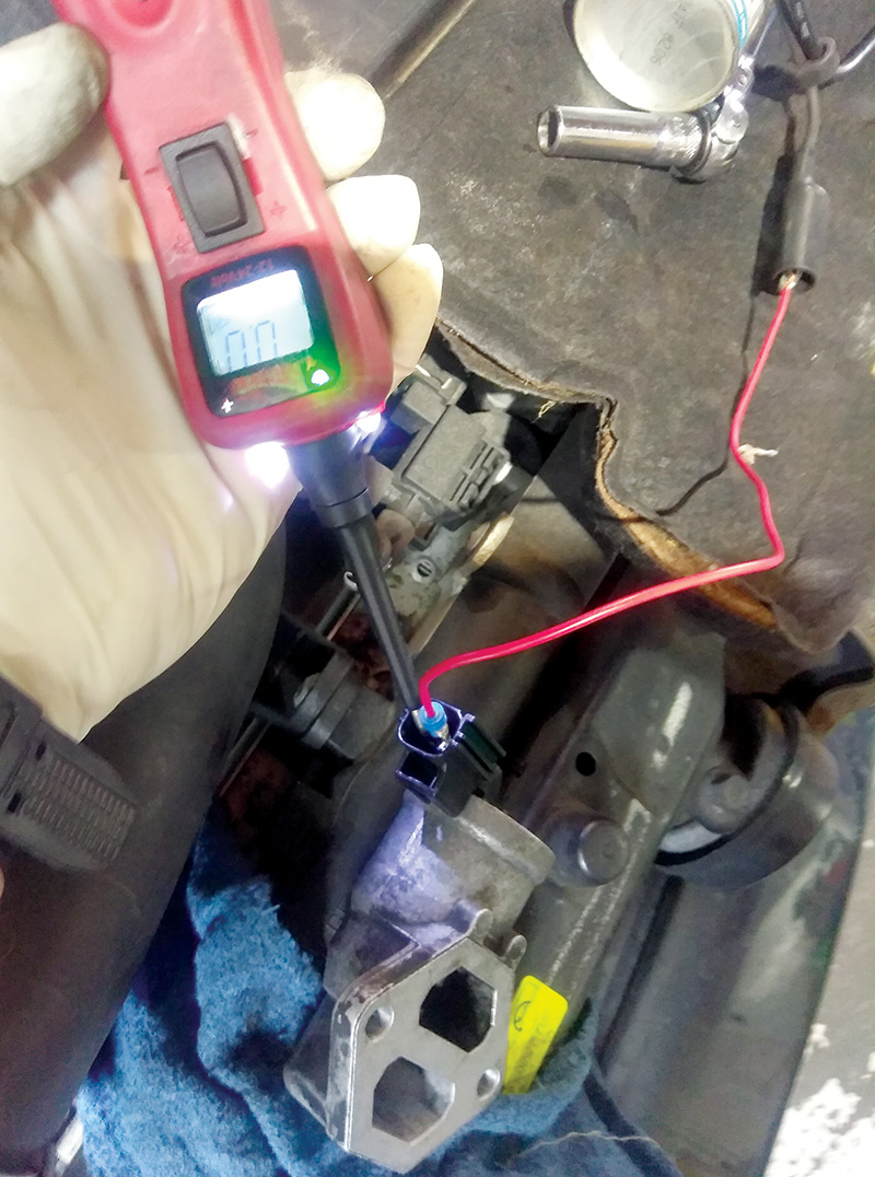
But if you command the IAC with VIDA or a scan tool you will eliminate any issues in the wiring to the valve.
In most cases the valve will be full of carbon and will be stuck or sticking when you apply power. You could clean the valve and put it back on with a new gasket, but replacing the valve and gasket with new Volvo factory parts will make sure you have a repair you and your customer can count on.
NOT SO COMMON HIGH MILEAGE VOLVO ISSUE
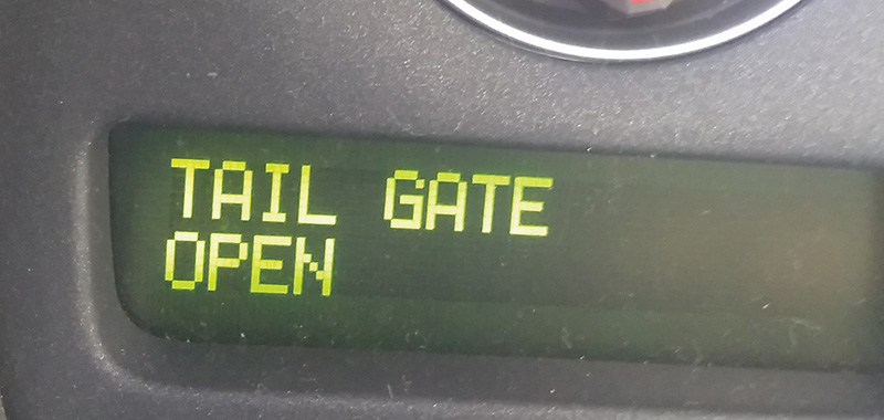
Tailgate Open warning on all the time on 1999 – 2008 V70 / XC90.
How many times have you had a Volvo wagon come into your shop with the Tailgate Open message showing up on the DIM display, even when the tailgate is firmly closed and locked? Most Volvo shops will see these cars come in on a regular basis.
Over years of grocery shopping and taking the kids to the soccer game, these tailgates and their components take a lot of abuse. The door lock mechanism gets locked, unlocked, opened, and slammed shut hundreds of thousands of times.
The door lock assemblies on these Volvos have a micro switch built into them that tells the Driver’s Information Module (DIM) if the door is open or closed. These switches can wear out after years of use and cause a false Tailgate Open warning to come on intermittently or all the time. In the majority of cases, a new door lock assembly is the solution.
Of course in some cases a worn or broken tailgate wire harness is the cause of this issue.
But what happens when you have just replaced that worn old lock assembly with a brand new shiny one you just got delivered from your local Volvo dealer’s parts department and the Tailgate Open warning is still coming on when the door is closed and locked?
The next logical step, unless you did this first, is to disconnect the tailgate wire harness connectors at both ends and use an ohmmeter to check for wires that are open or shorted.
(By the way, checking the wire harness for open or shorted wires should be done before you order that new lock assembly).
But what happens when you have that new part installed and you have checked the wire harness and it’s good, but the Tailgate Open message is still stuck on?
The signal from the door’s micro switch goes into the Rear Electronic Module (REM) and the Central Electronic Module (CEM) before it shows up on the driver’s information module.
It is possible that poor or corroded connections at these modules could cause this issue, but it’s unlikely.
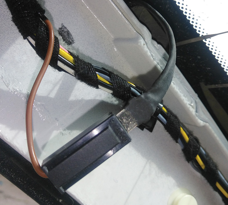
The tailgate lock assembly’s micro switch has two wires coming from it: one is the signal or powered side, and the other one is ground. What’s interesting about the ground side wire is where it gets its ground.
The pink powered wire comes from the connector on the REM, the ground wire gets its ground for the connector on the left side of the rear window glass break detector. This is a thin wire that is part of the rear window defroster grid. The left side connector gets its ground from the other side of the defroster grid after it passes through the grid.
So we all know that the later Volvo rear window defroster grids are very tough and rarely have issues, but the fact that the tailgate open or closed status switch depends on the rear window defroster grid being intact and the rear window not being cracked or broken can’t be overlooked.
The ground wire for the rear window defroster grid/glass break detector comes from the right side of the grid and runs though the tailgate harness and down to a body ground point (31/72) behind the battery.
In most cases there will be a break in the ground wire inside the tailgate wire harness near the point where the harness bends inside the body near the roof. But in some rare cases a break in the grid in the rear window glass can be the culprit.
This issue is more common in wagons that are used as the “dog car†because a lot of larger dogs like to scratch at the back window to get their owner’s attention. This scratching, of course, can cause breaks in the grid. The point is, check those wires for power and ground before replacing that part.
Download PDF


0 Comments