


Though you may rarely perform this job in your shop, it’s important that you understand how to check and adjust valve clearances. This knowledge will save you and your customers a lot of wasted time and money.Â
This article is about a job that you may rarely perform in your shop, but it is very important that you understand how to check the valve clearances and how to adjust them if needed. This knowledge will save you and your customers a lot of wasted time and money.
But you’re probably thinking to yourself, “Volvos don’t need valve adjustments,†and in most cases you would be right.
The fact is that Volvo has not had “valve adjustment†on their regular maintenance schedule since they used two digit engine numbers and cast iron engine blocks.
Some of you seasoned Volvo veterans have done these types of adjustments on the old B21 – B230 engines and probably still have the tools or maybe even a dusty box of assorted valve shims hiding somewhere in the shop.
If you have been in the automotive trade for a while, you might remember the old days when valve adjustments were a routine part of most car makers’ regular maintenance schedules.
Yes kids, in the olden days, an average technician could check the valve clearances and adjust the valves on most engines in less than an hour with very few tools.
And in a lot of cases adjusting the valves made a noticeable improvement in the engine’s performance, emissions output, and fuel economy.
That was the upside. The down side was that you had to adjust the valves a lot more often, and these older valve systems had a lot of limitations on how much efficiency and performance the car makers could squeeze out of the engines.
With the advent of hydraulic valve lifters, computer-controlled variable valve timing and camshaft control systems, the need for mechanically adjustable valves has widely become a thing of the past.
But there are still some cases where you will need to check and possibly adjust the valves on some late model Volvos.
If you’re relatively new to this line of work you probably have not had to perform many valve adjustments, unless you restore old classic cars or work on certain makes of Japanese cars.
If you are replacing the head gasket or replacing damaged valves after a timing belt jumped on any of Volvo’s 5 cylinder engines from 1995-2008, you should make it a habit to check the valve clearances when you have the camshafts removed for any reason, especially if the head has just been freshly overhauled at a machine shop.
Even if you have an outstanding machine shop perform the machine work on the head you should always take the time to double check the valve clearances before installing the camshafts, timing components, and camshaft cover.
There are many reasons that the valve clearances could be off.
Probably the most common possibility is that some of the valve tappets could have been mixed up in some way and it only takes one set of two to screw up your whole day. You may find, when you go to start the car after the job, that you have a misfire because one or more of the valve clearances is too tight and the cylinder can’t build enough compression.
And say, if for some reason, the valve tappets were not sent to the machine shop with the head and the machine shop lapped the valves. When you get your head back most likely all of the valve clearances will be too tight and in need of adjustment.
If this head is installed in this condition, the lack of valve clearance may cause some of the valves to not close fully, causing a loss of compression. This could cause low power or even a no start condition.
Don’t be the person who put one of these heads back together and found out too late that the reason the engine would not start (after a lot of testing and head scratching) was caused by low compression because the valves were not sealing well during the compression stroke.
Of course the opposite happens with valve clearances that are too loose.
When you start the engine for the first time after the cylinder head replacement, you may hear an audible clicking noise from the valve train and think to yourself, “Oh, it’s only the engine building up oil pressure. It will go away after the car warms up and it’s taken for a long test drive.†This statement could be true in some cases, but if any one of the valve clearances was too loose, no amount of “test driving†is going to fix that tapping noise.
You’re going to have to disassemble and adjust those valves in either case.
The moral of the story is to check those valves if you have the camshaft cover off for any reason.
Here is the procedure to check and adjust the valve clearances on a 2007 S40 with a B5244 non turbo engine, but the tools and techniques can be used on most Volvo 5 cylinder engines from 1994-2008.
CASE STUDY 2007 VOLVO S40 NON TURBO 2.4L (B5244 S7)
So let’s talk about what tools you are going to need to do this job.
Here is the list of Volvo special tools that you will need to perform this job:
If you need to purchase these or any other Volvo special tools, you can order them from your local Volvo dealer’s parts department or log on to volvotechinfo.com for tool information and an online catalog.
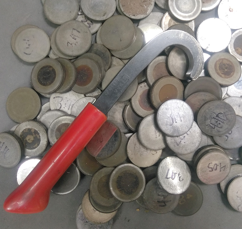
Volvo uses solid tappets in all of the P1 cars. The tappets are marked on the underside in tiny print and you will probably have to clean them off before you can read the size markings.
The tappets can be ordered individually from your local Volvo dealer’s parts department.
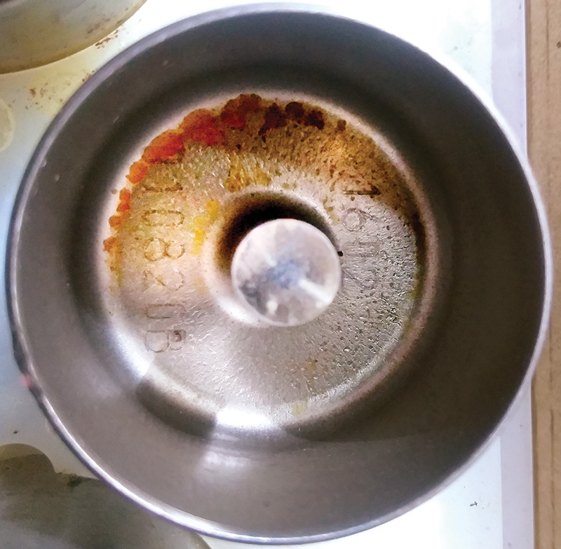
They come in 0.05 mm increments. Sometimes these tappets will need to be special ordered so make sure to double check your measurements before you order them because time is money and you don’t want to play that game.
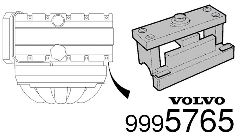
Volvo has a simple fixture (999 5765) that holds the camshaft down while the valve clearances are being checked.
Clearances are checked one cylinder at a time on each of the intake and exhaust sides.
If you already have the cylinder head removed you can still check and adjust the valve clearances on the bench using the camshaft holder fixture (999 5765).
If you are going to check or adjust the valve clearances you are going to have to get to the tappets first.
Start by disconnecting the battery at the negative post.
Next, you’re going to have to remove the timing belt and variable valve timing unit or hub assembly or assemblies in some cases where the car has both intake and exhaust VVT.
The next step is to remove the camshaft cover.
Start by carefully disconnecting the wire harness that is connected to the coils and VVT actuator and carefully move it to the side. These harnesses can have brittle insulation from years of heat, so when reassembling the head and hooking up coils be sure to look for any cracked wire insulation or loose connector pins.
Next, remove the ignition coils and spark plugs.
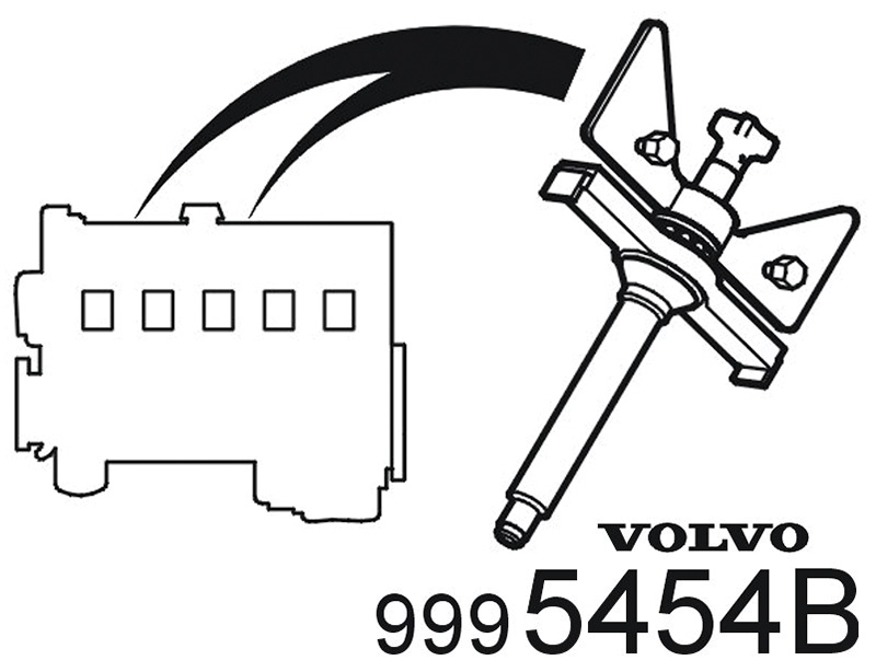
Lubricate the threads and install the big wing nut tools into the cylinder number 1 and 5 spark plug holes (999 5454 PRESS TOOLS) with 2-3 mm gap to the camshaft cover.
Ensure that the screw in the spark plug well is fully tightened.
Next, remove all the bolts securing the camshaft cover to the cylinder head.
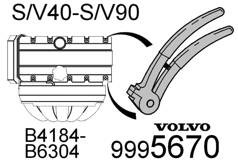
To get the cam cover to safely pop up off its dowel pins use pliers (999 5670) to help lift the cover from the cylinder head.
Install the pliers at the stop lugs in the corners and middle of the cam cover. Start with cylinder 1 and work alternately backward.
Slacken off the wing nuts approximately 2 turns. Repeat the procedure with the pliers.
Try not to use a screwdriver or pry bar to lever between the head and the cam cover as this may cause damage to the mating surfaces and may cause an oil leak or damage to the camshaft bearing surfaces.
When the cam cover is free, remove the wing nut tools and carefully lift the cam cover straight up and off the cylinder head. Pulling it up from one end could cause damage to the cam cover.
The camshafts may want to come with the cover when you remove it, so be careful not to let them hang from the cover and DO NOT pull the camshafts out of the cover from one side. This can break parts of the cover off and then you will have to replace it.
Now carefully push out the camshaft seals
Take care not to damage the sealing surfaces on the camshafts when removing them and storing them.
Next, remove the wing nut type tools (999 5454), the camshaft cover and the camshafts.
Use a rag with some parts cleaner on it to clean off the tops of the tappets so you can use a felt tip marker to write the position on each one before you remove them.
Use a magnet tool to remove the tappets and keep them together in order in a box or on a magnetic parts tray.
Use a razor blade or a gasket scraper and gasket solvent on the camshaft cover to remove residual sealant.
Do the same on top of the cylinder head mating surface.
Do not use air tools with abrasive disks for cleanup. This can cause permanent damage to the delicate aluminum sealing surfaces.
Use an air gun to blow all surfaces clean.
Next, carefully tap the end of each valve stem to ensure that the valve is correctly located in the seat.
Use a plastic, aluminum, or brass drift to protect the valve and the surface of the tappet.
The sound made by tapping will let you know if the valve is correctly seated.
Now it’s time to check those clearances.
Start by installing both the tappets for the inlet valves at cylinder number 1.
Note! Only install two tappets. The tappets should be placed at the same cylinder!
Intake valve: .0.20 ± 0.03 mm.
Exhaust valve: .0.40 ± 0.03 mm.
Position the intake camshaft so that the lobes at cylinder 1 point upwards.
Apply a little oil to the cam lobe and the upper side of the tappet to facilitate later measurement.
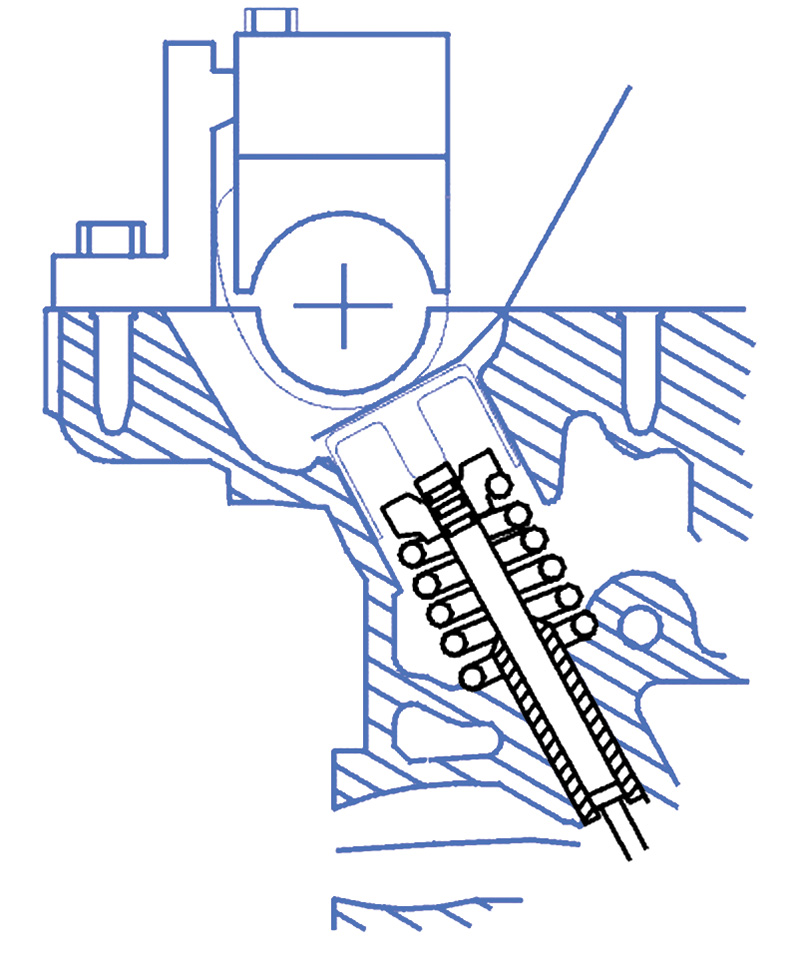
Install the lower section of camshaft press (999 5765 Holder camshaft) by the inlet valves for cylinder 1.
Tighten the tool against the cylinder head. Tighten to 17 Nm.
Turn the camshaft until it stops against the camshaft press.
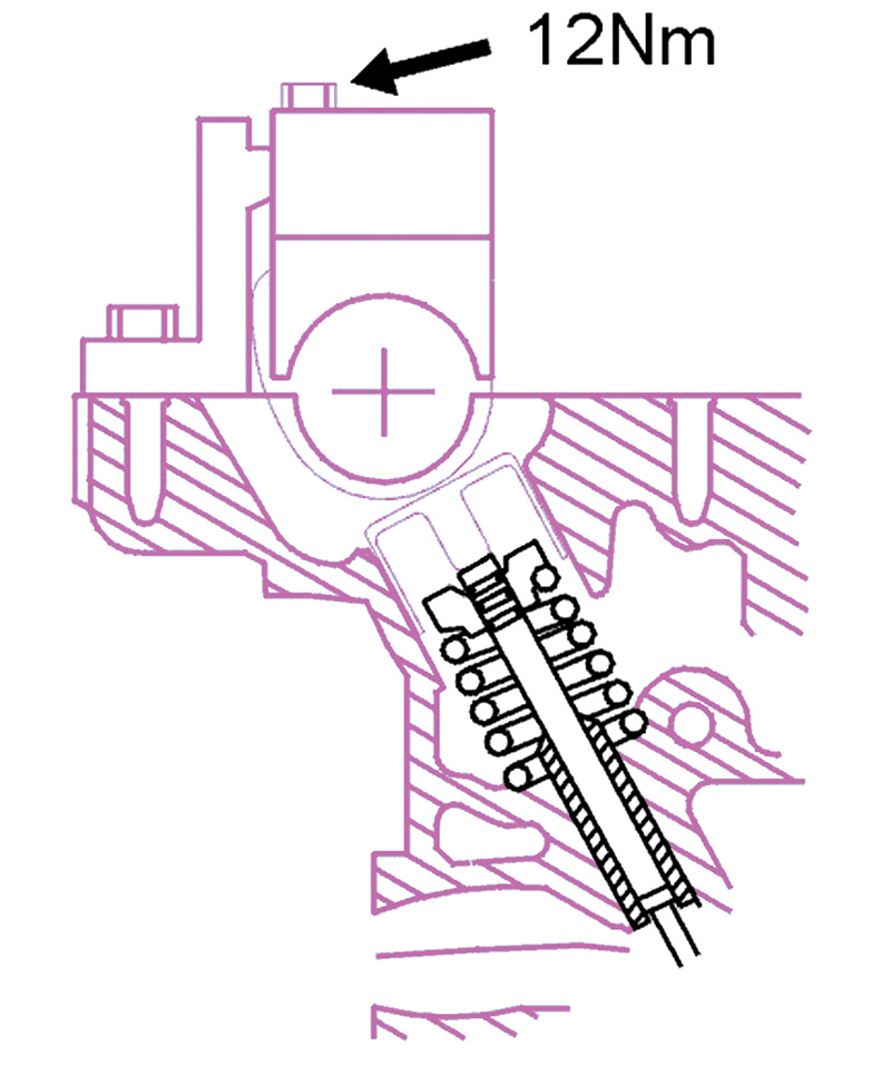
Install the upper section of the camshaft press.
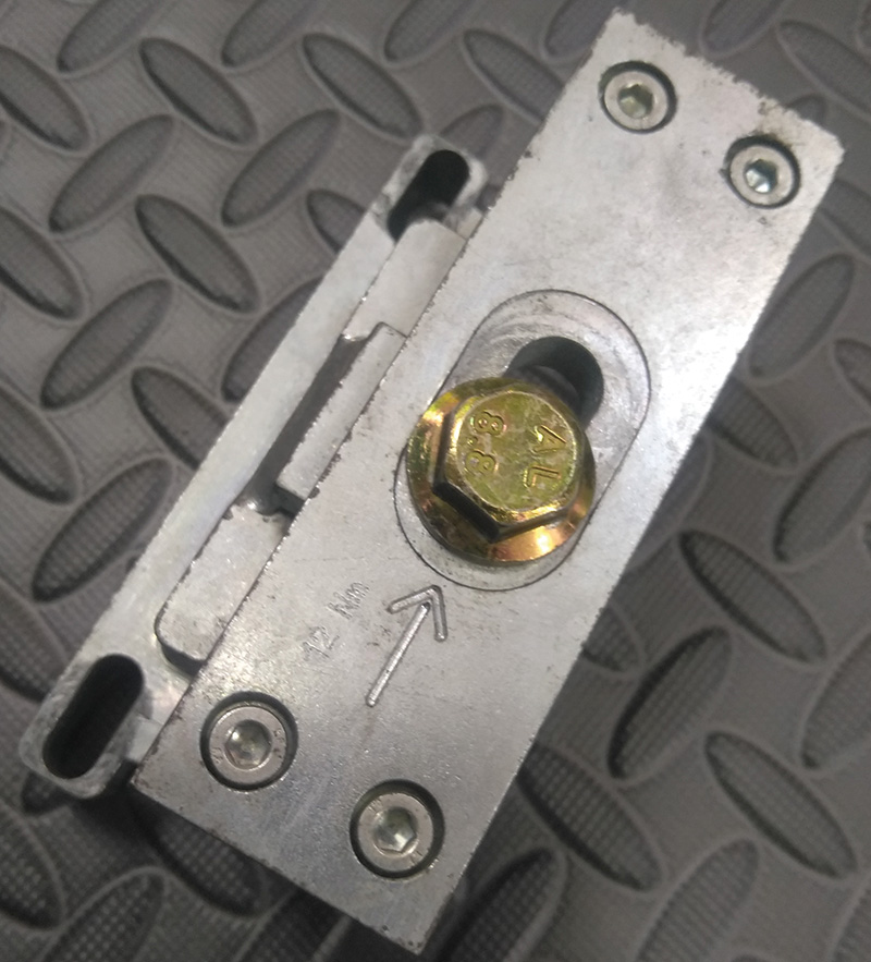
Tighten the screw which tensions the camshaft. Tighten to 12 Nm.
Remember measurements must only be taken on a cold engine.
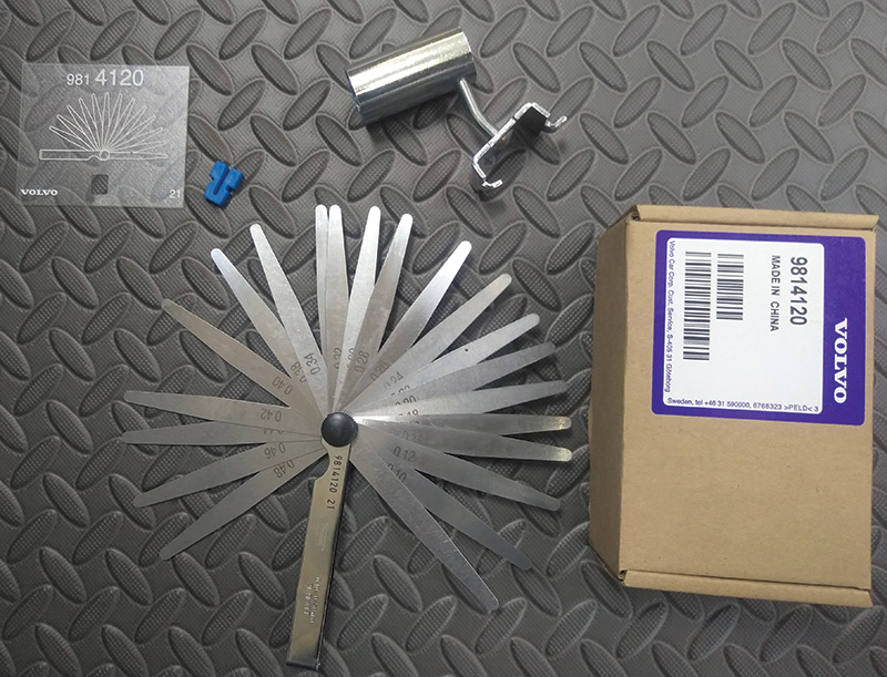
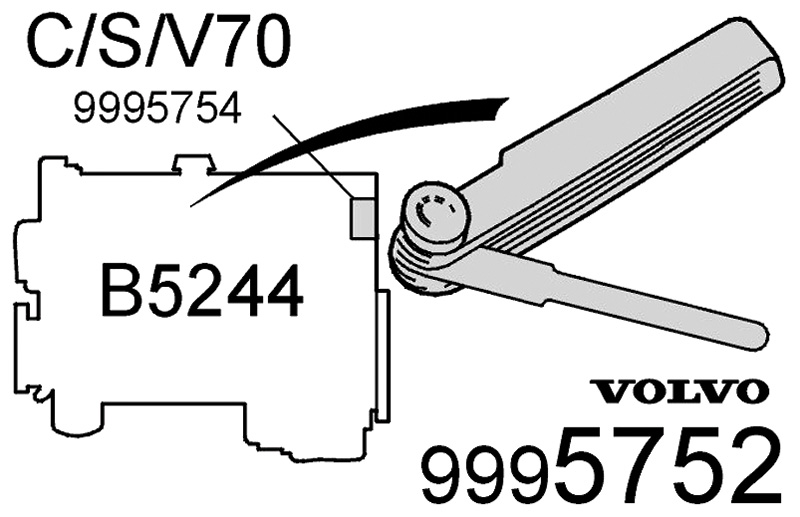
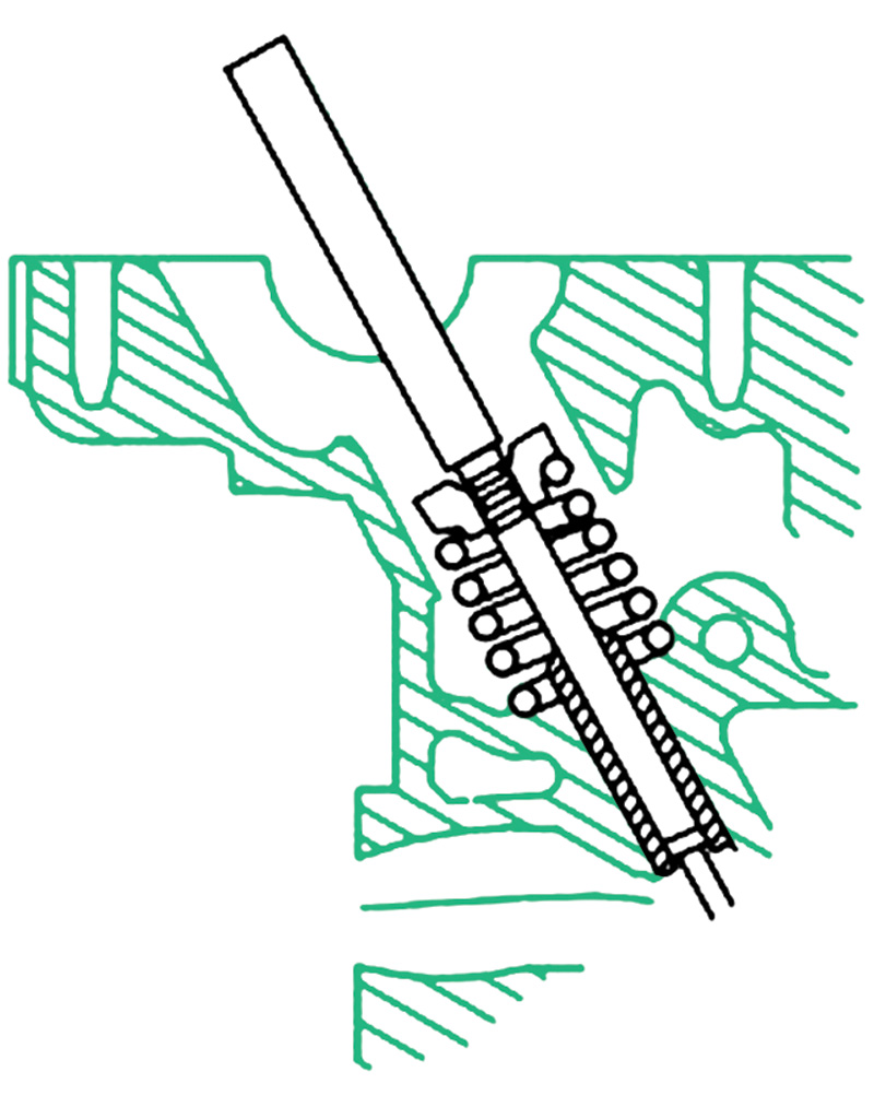
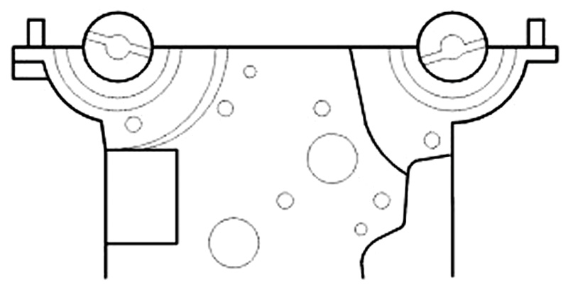
Use feeler gauge (999 5752) or similar feeler gauge and press with a finger so that the feeler gauge lies parallel to the upper side of the tappet (see illustration).
Move the feeler gauge sideways when taking the reading in order to obtain as accurate a measurement as possible.
The clearance specs on the B5244S are:
- Intake valves: .0.20 ± 0.03 mm.
- Exhaust valves: .0.40 ± 0.03 mm.
It’s a good idea to draw a diagram with a map of the tappets so you can make notes about those that need to be adjusted.
Correcting measured clearance
Lift out the upper section of the press tool.
Lift out the camshaft.
Adjust the play by replacing the tappets with new ones that are smaller or larger to achieve the correct valve clearance.
Reinstall the camshaft and the upper section of the press tool. Tighten to 12 Nm.
Make a new valve clearance measurement.
When the correct valve clearance is achieved:
Remove:
- the press tool 999 5765
- the camshaft
- the tappets.
Note! Carefully mark the tappets with a marker before you remove them from the cylinder head so that they won’t get mixed up and installed in the wrong order.
Installing tappets and camshafts
Lubricate the valve guide wells with engine oil.
Install all the tappets.
Lubricate the camshaft bearing seats and the upper sides of the tappets with oil or assembly lube.
Position the intake camshaft so that the groove at the rear edge of the camshaft is above an imaginary center line.
Position the exhaust camshaft so that the groove at the rear edge of the camshaft is below an imaginary center line.
Before applying the liquid sealant and installing the camshaft cover make sure that the mating faces are clean and free of foreign material.
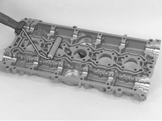
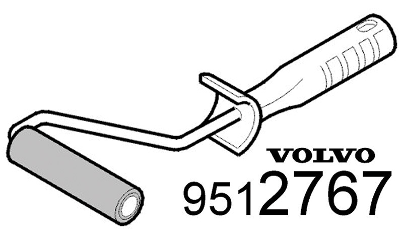
Use a clean roller like Volvo tool 9512767 to apply the liquid gasket (Volvo p/n 1161059) to the camshaft cover.
Ensure that no liquid gasket gets into the oil galleries.
You can use a disposable paint tray or a clean piece of laminated cardboard to squirt some of the liquid sealant on so the sealant can be evenly spread across the roller’s surface; this will ensure even application.
After rolling the liquid sealant evenly onto the camshaft cover install five new spark plug tube o-rings and place the cover back onto the cylinder head using the guide pins to line it up.
Reinstall the wing nut press tools (999 5454) and evenly tighten them down to press the cam cover close to the head.
Install and start all the cam cover bolts and begin to tighten the bolts from the middle and outwards.
Reassemble the rest of the cylinder head parts and timing components and give the car a good test drive.
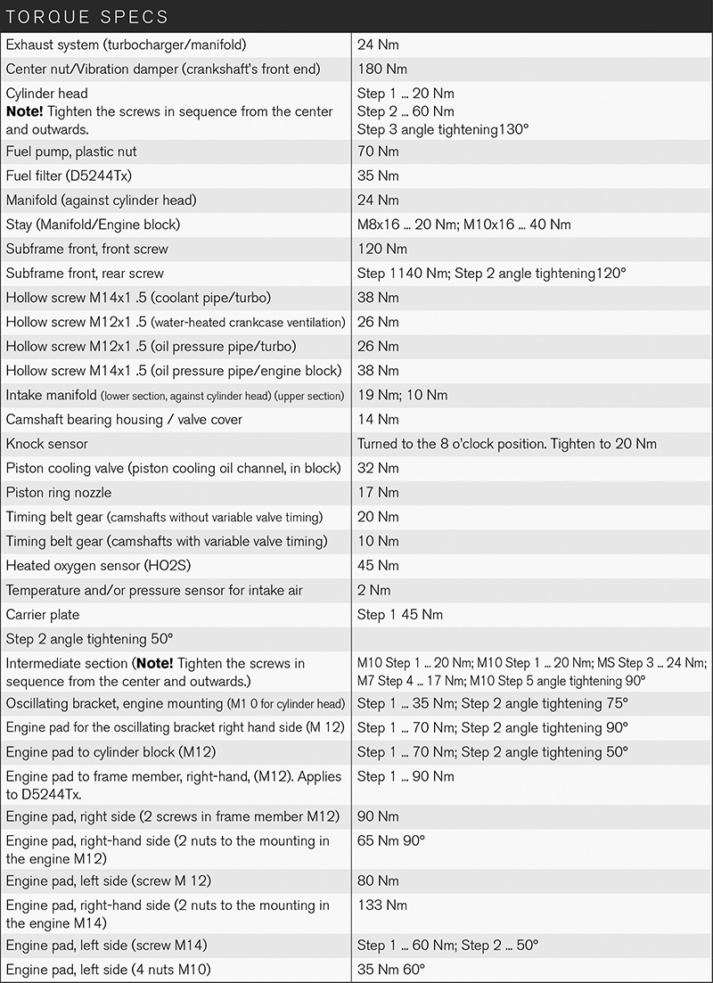
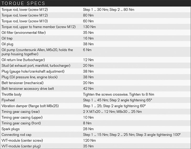
Here is a list of the torque specs for this engine.


0 Comments