


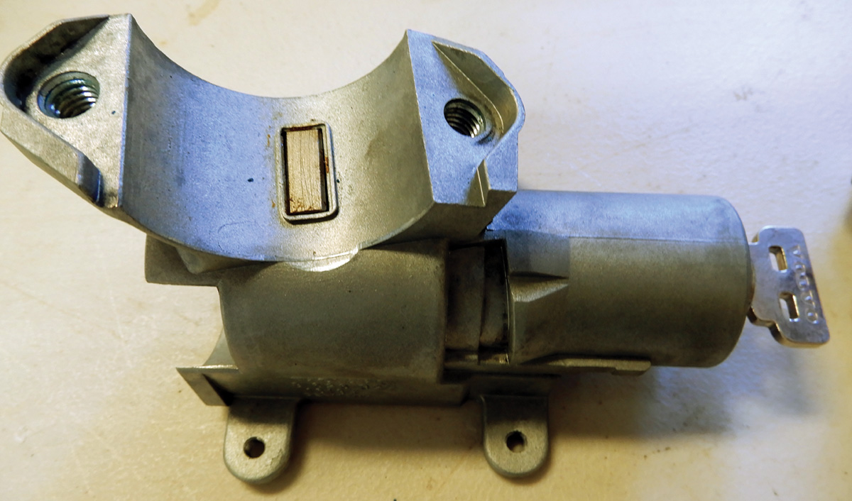
Volvo’s ignition lock assemblies for the 1999 – 2009 models are quite similar with a few different features through the years. These ignition locks had the basic key fitting into a tumbler connected to the steering column. Through the years basic wear will start to deteriorate the key and tumbler, and the ignition lock assembly will need to be replaced.
Replacing ignition lock assemblies can sometimes be quite difficult and sometimes hard to diagnose. The right tools and know-how make this job a lot less challenging.
There are many ways an ignition lock assembly can malfunction. Consider an ignition lock assembly in which the key just spins around in circles and sometimes works fine. Other times, the key won’t turn at all. There are times the key will get stuck in a certain position and won’t release. In most of these cases, replacing the ignition lock is required.
The lock cylinder and ignition switch are two separate components. The lock cylinder is the portion that the key slides into, and allows the ignition switch to turn when the correct Volvo key is inserted in the ignition lock assembly. This is one of the vehicle’s lines of defense against theft.
The lock sensor or antenna ring receives the ignition key and, if the proper key is inserted, small actuators on the lock cylinder will allow the lock cylinder, and ignition switch, to rotate. Also, the ignition switch on most vehicles should remain locked if the transmission is in Park or Neutral, and some models will only unlock once the brake is applied in Park or Neutral. This is a safety feature, called the shift ignition lock interface, that connects or communicates information from all three sensors to prevent the vehicle from starting in a harmful manner. The ignition lock cylinder must also be released by this system to turn.
The mechanical lock cylinder assembly wears out from normal use. Lock cylinders fail fairly commonly, but mostly on higher mileage vehicles. The lock cylinder may become difficult to turn or it gets jammed. If this is happening, try a different key before condemning the lock cylinder. Worn out keys over the years can cause problems, and sometimes a new key can cure the problem.
Often, people put other keys and items on their key rings, making them heavy on the ignition lock assembly when inserted in the lock. This pulls the lock angle down so that the key doesn’t slide in as well, making the lock assembly wear out much faster. Suggest to your customers that they try not to weigh down the key ring.
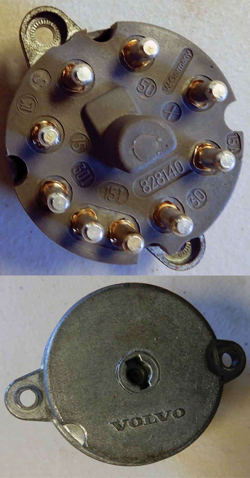
The electrical switch also wears out, creating a no-start condition or electrical problems. In some instances this electrical switch can get jammed and cause the key not to turn. Make sure to check before replacing the complete ignition lock assembly.
Dash warning lights staying on, radios not working, and many other problems can be caused by a faulty ignition switch. If you find low voltage to fuses or other weird electrical problems, check the power out of the switch. It should match battery voltage. If it does not, there may be resistance inside the switch, dropping the voltage and causing the vehicle problem.
Ignition lock assemblies will need to be ordered through your local Volvo dealer. The lock assembly must be specified by VIN (Vehicle Identification Number) for that vehicle. This is so existing keys will match. This would be the time to order new keys if needed. Note that the lock assembly doesn’t come with new keys. So any new keys would have to be programmed to the specific vehicle.
Some ignition locks get stuck in certain positions that make it more difficult to work with when replacing. For example, if the key won’t turn at all, this makes replacing a little more difficult.
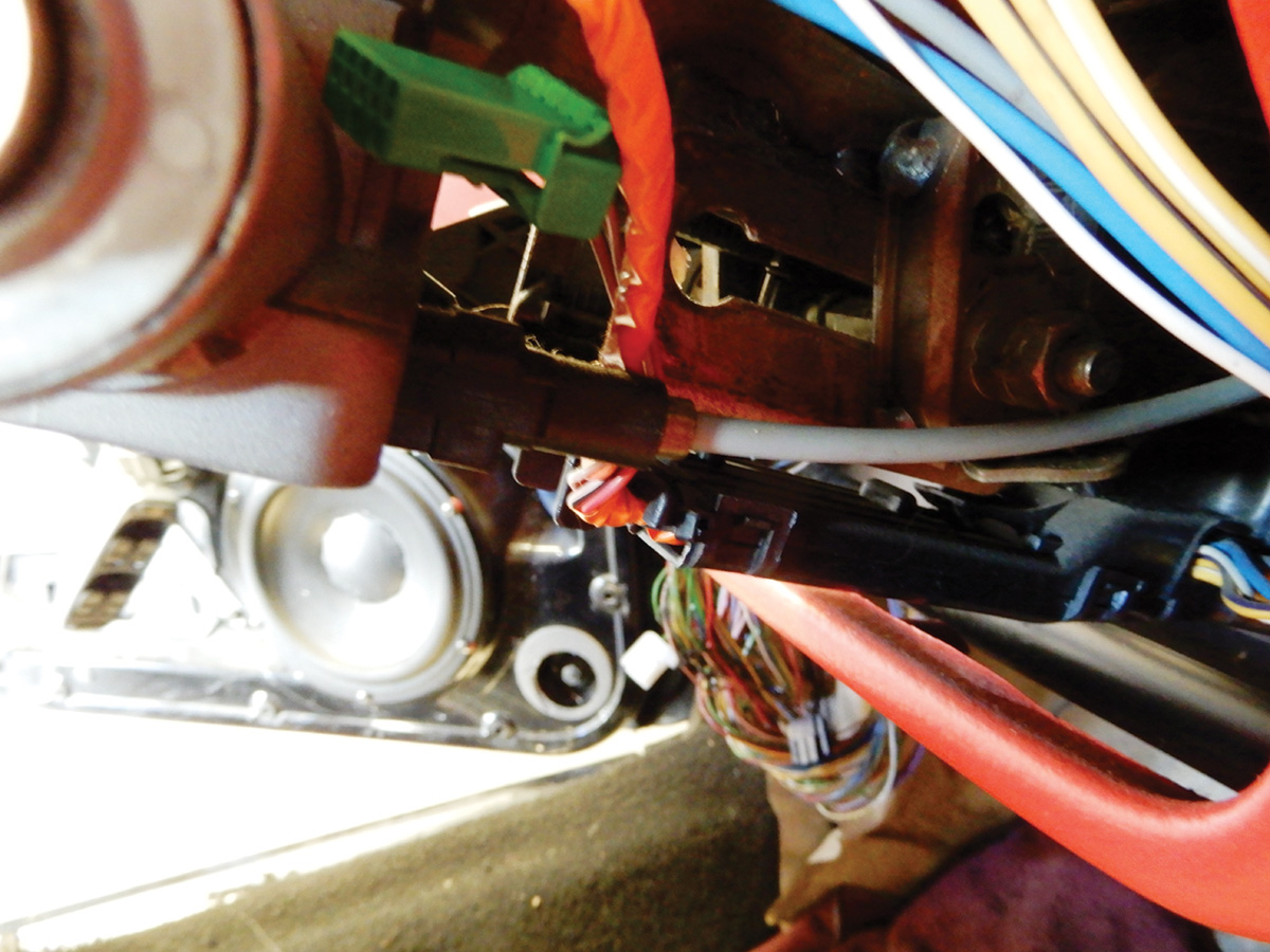
As an example, here’s the procedure for replacing the ignition lock assembly on a 2000 S80. Remove the negative cable at the battery to make sure not to short any electrical components. Lower and extend the steering column towards the driver’s seat. This will give room to work on the lock assembly.
Remove the trim around the steering column so to expose the ignition lock assembly. Remove the T25 lower steering column trim screws. Then pull the upper trim straight up to remove. Removing the steering wheel makes the job much more accessible. When removing the steering wheel, remove the air bag first.
The supplemental restraint system (SRS) is active for a certain length of time after the power supply has been disconnected. Wait for a minimum of 30 seconds before disconnecting or removing any SRS components.
Make sure to use the screw to hold down the clock spring that is supplied in the steering wheel. Not doing this can damage the clock spring. Make sure the steering wheel is pointed straight ahead and mark the steering wheel to the column so it is reassembled properly.
Now that the steering wheel is off and the trim has been taken off, unplug all electrical connectors. Unplug the connector to the electrical part of the ignition switch. This is the juice for the switching mechanism. Remove the switch with a T20 Torx driver.
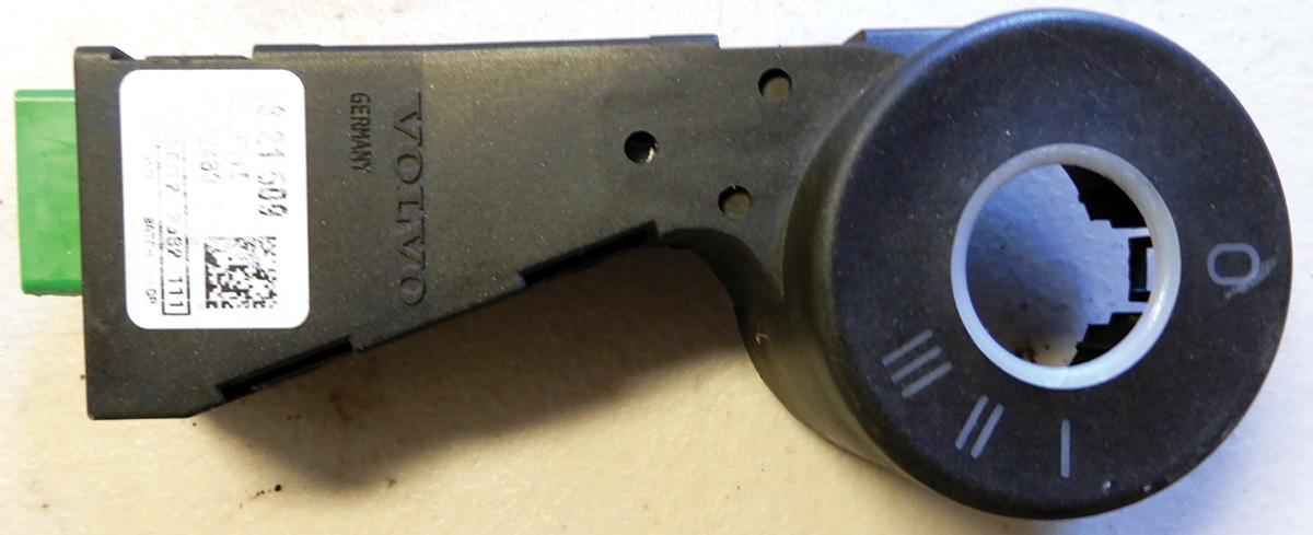
Now it’s time to remove both switches on each side of the column, the turn signal switch and the windshield wiper switch. Remove the antenna ring around the ignition lock. This antenna ring is designed to communicate with the chip or transponder in the key that sends a signal to the immobilizer and ECM (Engine Control Module) to start the vehicle when the key is turned.
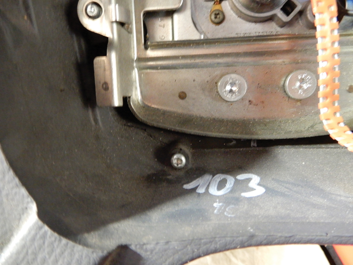
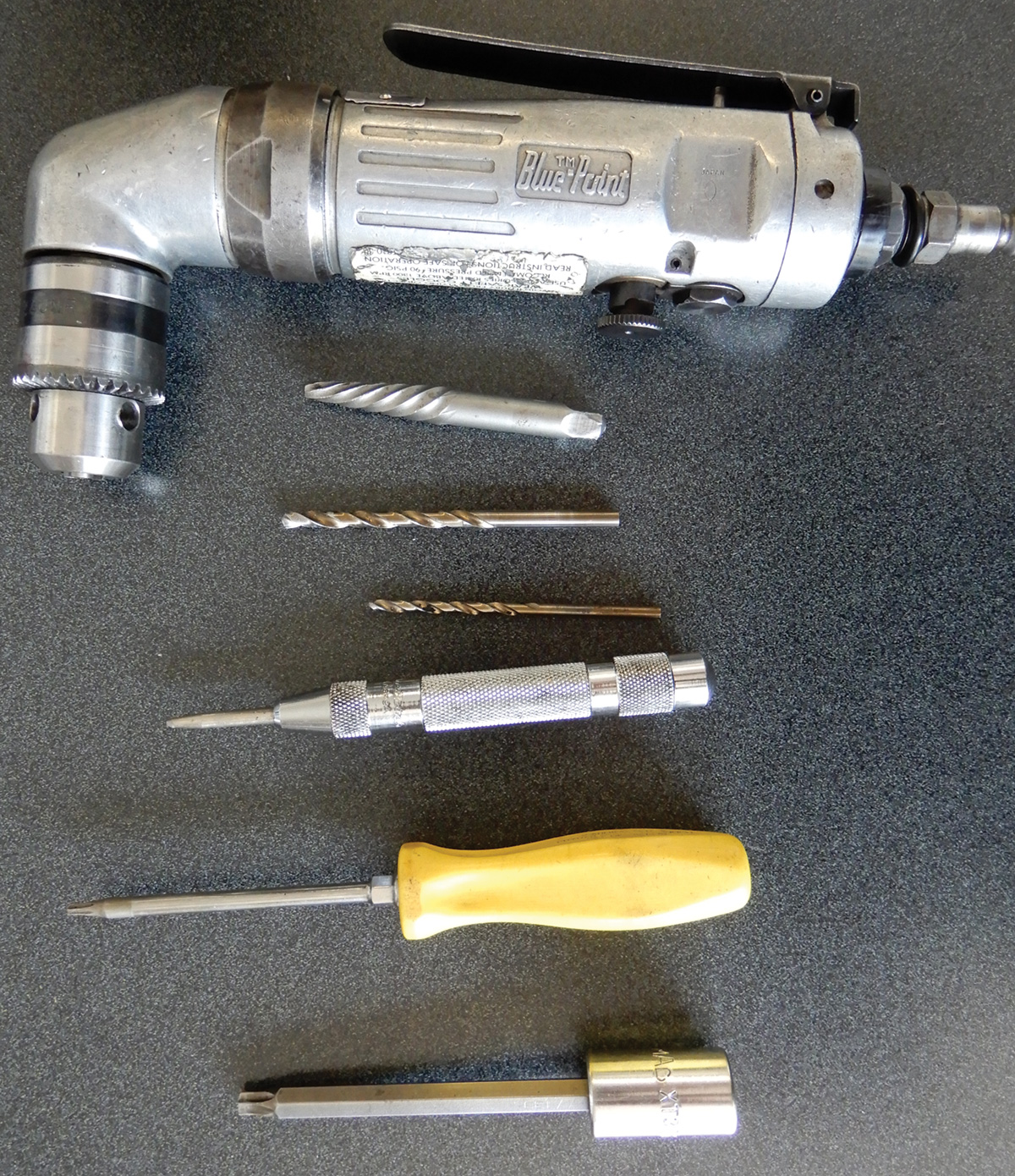
Now that everything is out of the way, drilling the tamper proof bolts will be the next thing to do. Always protect your eyes with protective glasses when working with drilling of any kind. A good center punch, sharp drill bit and drill will be needed. Now this is a very important procedure. Make sure to center punch the bolts correctly. This is where removing the lock can get very hard to do. Always make sure to center punch in the middle of the bolt and drill slowly with a straight shot into the bolt. Starting with a smaller drill bit, like 1/8 inch, and then move up to a bigger bit that will be a perfect fit for an easy-out type tool to remove the bolts.
Once the bolts have been drilled, carefully unscrew the bolts from the lock assembly. Now that the bolts have been extracted, the lock assembly will be able to be removed. Make sure to turn the key to position 2. That way, removing the cable for the transmission shifter can release. Make sure to clean up all drilling debris so that particles don’t get into any electrical parts or connectors. Using a magnet will help in this process.
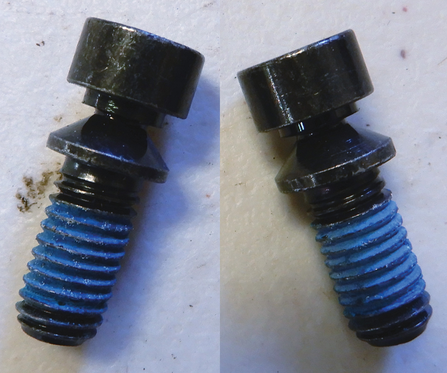
The new lock assembly will come with two shear bolts or security bolts. Once the lock assembly is in place around the column, make sure the steering lock is properly engaged in the steering column slot. Tighten the bolts until the tips break off.
Once the ignition lock assembly is in place and tightened down, you can secure the cable into the lock from the shifter. Now we can connect wiring and install the antenna ring, turn signal switch and wiper switch. Insert the key and make sure the ignition lock works properly. It’s always a good idea to insert the key into the lock before installing just to make sure we have the right lock assembly.
Now that the lock assembly is installed and all wiring has been connected, it’s time to reassemble the trim around the switch. Secure the steering wheel and remove the screw that was holding the clock spring in place. Set the air bag back into place and tighten down. Connect the battery and make sure all switches and the ignition lock work perfectly.
The following is the procedure for removing the ignition lock assembly from a Volvo XC90. Much like that in the S80, the mechanical ignition lock looks very similar. Tools you will need to replace the lock assembly are T25 and T20 Torx drivers, a socket for removing the steering wheel, and drill bits, drill, and center punch.
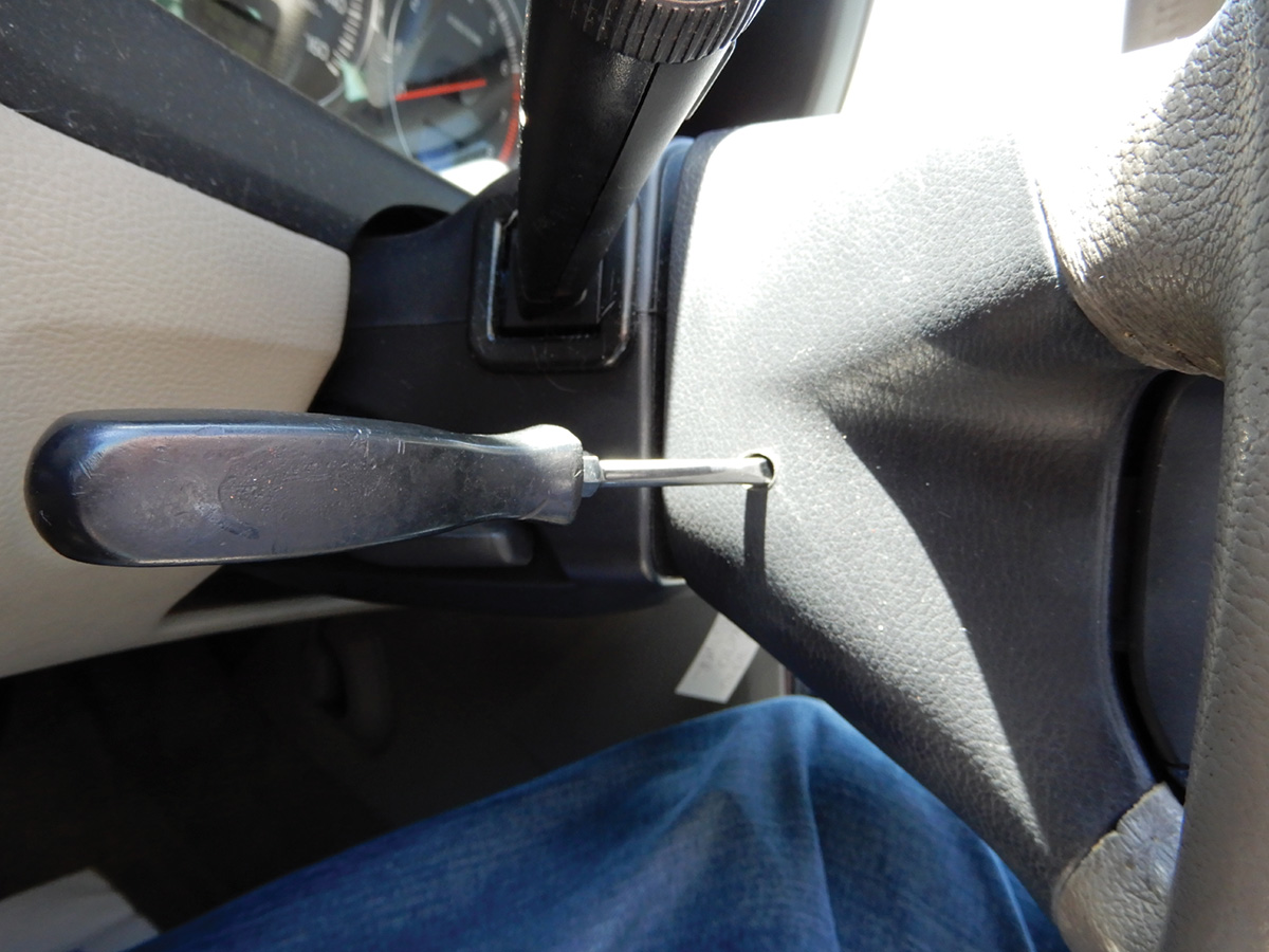
Turn the steering wheel ¼ turn so both screw holes are accessible in the rear of the steering wheel. Insert a screwdriver of medium size on the back side of the wheel. The screwdriver must be at a right angle to the rear surface of the steering wheel. Position the screwdriver point at the top of the spring inside the steering wheel. Pry the screwdriver up against the upper edge of the hole so the point of the screwdriver presses down the catch until the catch releases. Do the same with the other side. Remove the electrical connector from the air bag and remove the bag. Place on flat surface face up.
Never tamper with an air bag or hook a volt meter to it. This could cause the air bag to deploy.
Now that the air bag is removed, turn the steering wheel to the straight ahead position, adjust the column and extend it towards the front seat. This will give room to work on the ignition lock assembly.
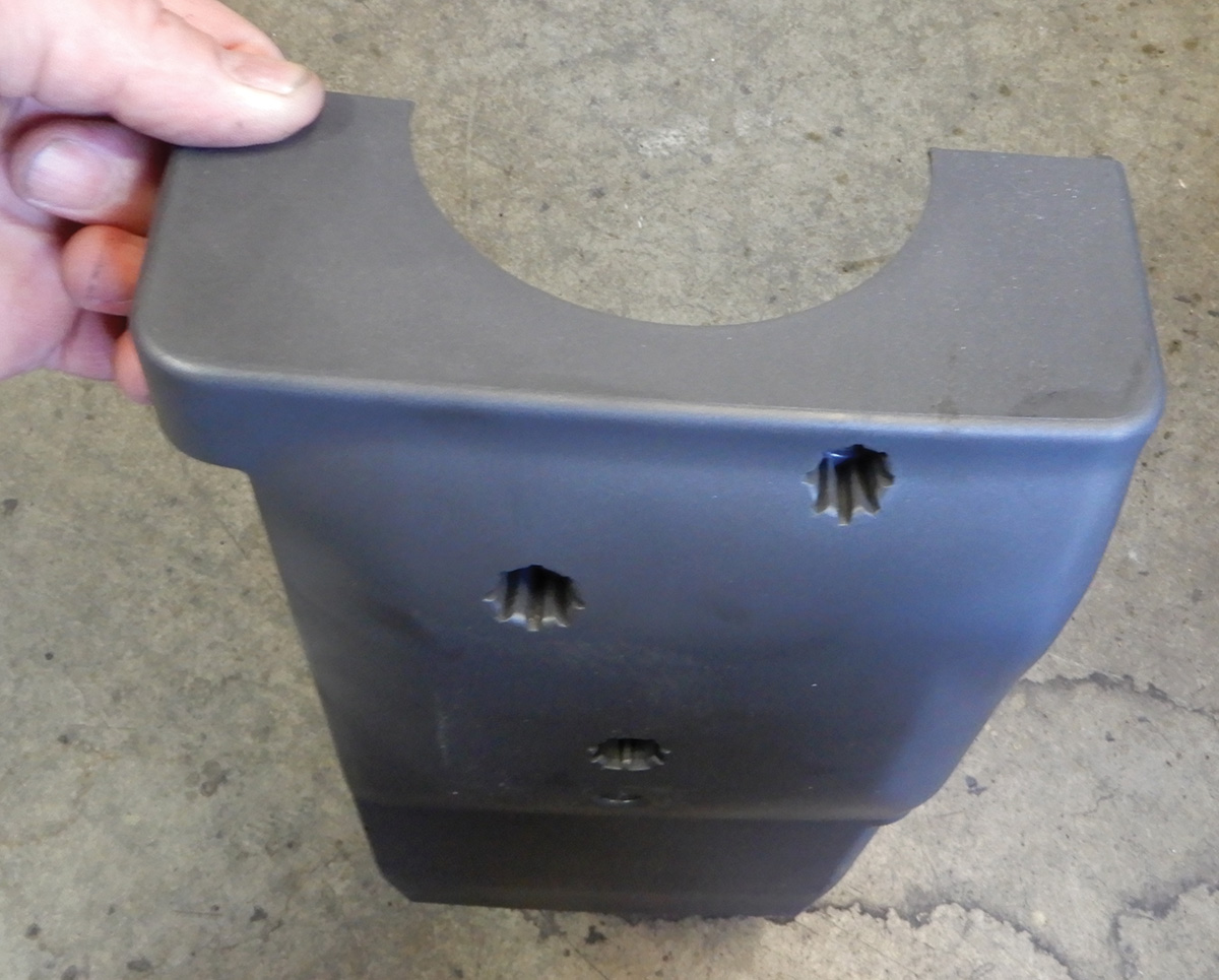
Insert the lock down screw into the clock spring so that the clock spring doesn’t move. The screw should be in the steering wheel specifically for this reason. Now that the clock spring cannot move, remove the steering wheel and be sure to mark the position so you can reassemble it in the same place. Remove the steering column covers. Remove the three T25 screws and remove the cover over the ignition lock assembly. Pull the top cover straight up and fold it back out of the way.
Press in the snap connector and remove the antenna ring around the ignition lock and disconnect the electrical connector. Adjust the key to position 1 and remove the interlock cable from the shifter assembly. If for some reason the key will not move, it will be necessary to replace the cable for the interlock. Remove the screw that holds in the wiper switch and the turn signal/high low beam switch. The steering wheel module will need to be disconnected and removed.
Remove the electrical connector to the ignition switch opposite of key entry. Unscrew the two screws that hold in the ignition switch electrical part.
A 90 degree drill might work the best. Insert a 1/8 inch drill bit into drill. Center punch the very middle of the security/break-off bolts. This step is very important and should be done properly, so be certain to drill straight into the bolt and not at an angle. Not doing this correctly can make the job very difficult.
Now that both holes are drilled at 1/8 inch, use a bigger bit, 11/64, and drill both holes again. Using some sort of easy out tool, extract both bolts until they come out. The ignition lock assembly will now come apart from the steering column.
Make sure to clean up all debris and metal particles. A vacuum cleaner and magnet are good tools to do this.
Insert the ignition key into the new lock assembly. Check to make sure the key is in position 1 and that the locking lug on the steering assembly lock is down. Install the new steering lock against the cap on the steering column. Install the new security/break-off bolts and tighten until the heads break off.
Put the gear selector shifter into Park. Insert the key and turn to position 1. Press the cable for the gear selector into the ignition lock assembly and feel to make sure it’s in position. Remove the key and make sure the vehicle doesn’t come out of Park.
Install the electrical part of the ignition and connect. Install the steering wheel module and connect. Install both switches at the steering column and connect. Install the antenna ring around the ignition lock assembly and connect.
Install the lower steering column cover with the three T25 Torx screws. Make sure not to trap any wires when installing the cover. Fold down the top cover and snap into place. Make sure that all rubber trim is in the correct position. Install the steering wheel to the position previously marked and remove the screw for the clock spring. Tighten down the steering wheel and connect air bag wiring and snap the air bag into place.
Connect the battery and check that all key positions work properly and that the vehicle starts correctly. If other keys are ordered, downloading software will have to be performed to make the key work correctly. Check that the shifter works properly and that, with key out of the ignition, the shifter will not come out of Park.
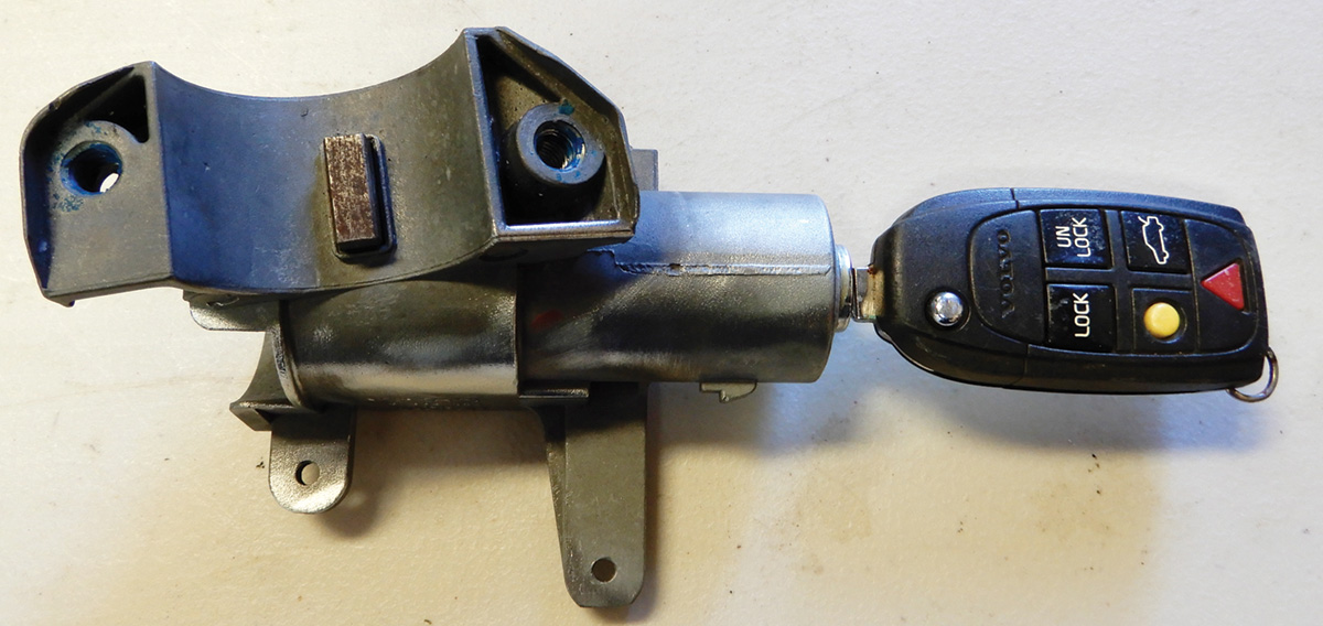
Volvo’s ignition lock assembly through the years has changed somewhat but the various designs are very similar, consisting of a basic tumbler coded for keys and fitted into an aluminum base that is secured at the steering column. There are some electronics involved, like the antenna ring for the immobilizer, so the chip in the key will communicate with the vehicle. This is also a theft deterrent provision.
The newer model Volvos will have a keyless entry that will have no key and only a remote device that will be able to communicate with the vehicle and be able to start it without turning a key. These systems will be more convenient for Volvo owners and will eliminate the old key lock assembly.
Download PDF


0 Comments