


Volvo engines have been fuel injected for many years, but the fuel injection system has changed a bit. We will go over different systems used through the years, how to maintain these systems, and the various problems that might occur.
When working on fuel systems, any time there is a fuel system leak, be sure to disconnect the battery before any repair.
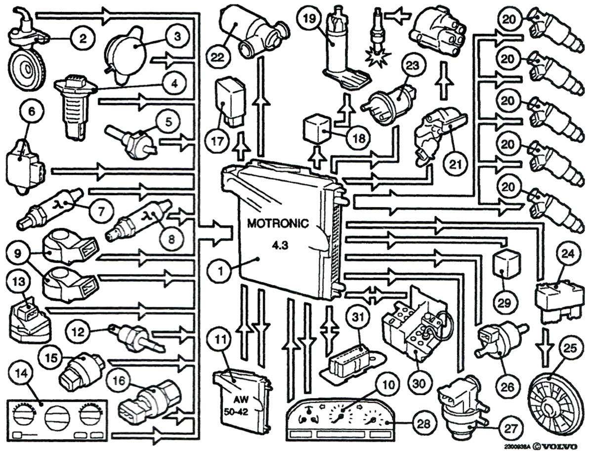
On the 240, 740, and 940 vehicles, the injection systems were all Bosch-designed systems. These systems primarily used these components:
| electric fuel pump | fuel accumulator |
| fuel filter | fuel pressure regulator |
| fuel distributor | fuel injectors |
These systems worked well, but as time went on, more strict emissions standards were introduced and the systems changed. Evaporative emissions systems were upgraded to keep fuel vapors from escaping into the atmosphere.
In 1994, the Volvo 850 Turbo was fitted with Motronic 4.3 fuel injection. The new system was a complete system with a control module that controls fuel flow, idle speed, ignition timing, engine cooling fan, EGR system, EVAP system, air conditioning switch, and the boost control for the turbo. There was also an on-board diagnostic system.
Motronic 4.4 came along and added some more features, including:
- Atmospheric pressure sensor
- Outside temperature sensor
- Modified location of rear oxygen sensor. The sensor was moved forward and right behind the three way catalytic converter.
- A more effective EVAP system
- The fuel regulator is located above steering rack on right side of vehicle and the hose routing is different.
The Motronic 4.4 B5254S fuel pressure regulator is connected in line, so pressure stays at 300 kPa (43.5 psi). This will give an accurate control for the Engine Control Module (ECM) to work on a non turbo engine.
With no return line from the fuel rail, the engine will not heat the fuel, and the fuel temperature will remain low to reduce evaporation from the fuel tank.
The Motronic 4.4 system was a very reliable system with little trouble. Keeping the vehicle maintained correctly is a big key. Changing the fuel filter, changing spark plugs and air filter every 30,000 miles, and using the correct fuel with the right octane — all these things need to be done to keep a Volvo running in top shape.
Volvo EVAP System
The components of a 1998 Volvo S70 EVAP system:
- Canister purge valve
- EVAP canister
- Shut-off valve
- Filter
- Fuel tank pressure sensor
- ORVR valve
- Rollover valve
- Motronic 4.4 ECM
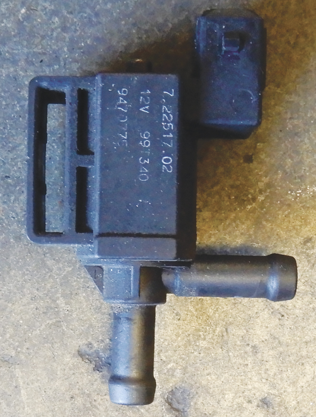
Canister purge valve (CP)
This valve controls the flow of fuel vapor and air from the EVAP canister to the engine. The valve is controlled by the ECM.
EVAP canister
Hydrocarbon vapor coming out of the fuel tank is dealt with by the EVAP canister. To minimize pressure drop in the lines between the fuel tank and the EVAP canister, the EVAP canister is located close to the fuel tank. The EVAP canister volume is 2.1 liters. A new type of carbon reduces pressure drop in the gas flowing through the EVAP canister.
EVAP Canister Shut Off Valve
The valve is located close to the EVAP canister. The valve is part of the leak diagnostic system and temporarily closes the EVAP canister fresh air intake during the diagnostic test.
The filter is connected to the EVAP canister shut-off valve in line with a hose.
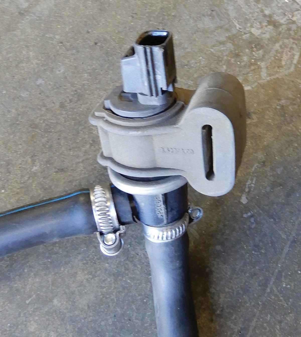
The pressure sensor is located in line with the ORVR valve and provides information about fuel tank pressure.
The ORVR valve has two functions: the rollover valve, which closes off fuel at the EVAP line so fuel won’t escape if the vehicle has rolled over, and also a float valve that closes when the fuel tank is full.
Rollover Valve
The rollover valve is mounted high on the fuel tank, and a small EVAP line runs from it to the ORVR valve. The rollover valve lets the fuel tank breathe when the ORVR valve is closed after the vehicle has been fueled up.
Montronic 4.4
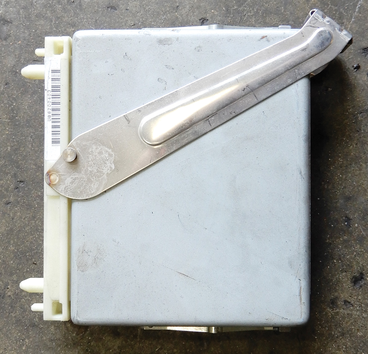
The ECM controls all functions in the system during cold start and after warm-up.
The following is a description of how the EVAP system works.
When refueling starts, the check valve in the fuel tank opens. The fuel flow creates negative pressure at the top of the fuel filler pipe. This results in an air flow in the fuel filler pipe. It is important to have low resistance between the fuel tank and atmospheric pressure (via the EVAP canister shut-off valve filter) to stop fuel vapor from escaping from the fuel filler pipe. The principle of the system is called a dynamic seal.
When the fuel tank is full, the ORVR valve closes and the fuel tank pressure increases rapidly. This closes the check valve in the fuel tank, preventing fuel from coming out of the filler pipe when the fuel pump nozzle is shut off.
Fuel vapor in the fuel tank (together with air) reaches the EVAP canister via the ORVR valve. Fuel vapor is adsorbed by the carbon in the EVAP canister. If the ORVR valve is closed, the fuel tank is vented via the rollover valve.
When the canister purge valve (CP) is closed, the fuel vapor remains in the EVAP canister. When the ECM transmits an opening signal to the valve, vacuum from the intake manifold or from the fresh air intake creates a flow through the EVAP canister. The EVAP canister is connected to the outside atmosphere via the canister shut-off filter, which allows the flow to evacuate the EVAP canister.
The air flow through the EVAP canister removes stored fuel vapor, which flows to the engine and enters the combustion process. The canister purge valve (CP) pulses rapidly when the car is being driven and is idling.
How the EVAP System Carries Out Diagnostics
When the EVAP canister shut-off valve and (CP) canister purge valve are closed, the fuel tank system is now completely closed. Pressure in the fuel tank should be stable. If pressure drops the (CP) canister purge valve is leaking.
When the EVAP canister shut-off valve opens, the tank system is open. The (CP) canister purge valve is pulsed, and because of the negative pressure in the intake manifold, the engine starts to suck air through the EVAP canister. Because the EVAP canister shut-off valve is open, the pressure in the fuel tank drops slowly. If the pressure in the fuel tank drops rapidly the EVAP canister shut-off valve is clogged.
When the EVAP canister shut-off valve is closed, the (CP) canister purge valve continues to be pulsed, and pressure in the fuel tank should drop rapidly. If pressure does not drop enough, there is a large leakage in the fuel tank system. A Diagnostic Trouble Code (DTC) will be stored.
When the canister purge valve is closed, the EVAP canister shut-off valve is still closed, so there is negative pressure in the fuel tank. The negative pressure in the fuel tank should be stabilized. If pressure starts to increase too quickly, this indicates a small leakage in the system. A diagnostic trouble code is stored. When the EVAP canister shut-off valve opens, the EVAP function is enabled and the diagnostic test is finished.
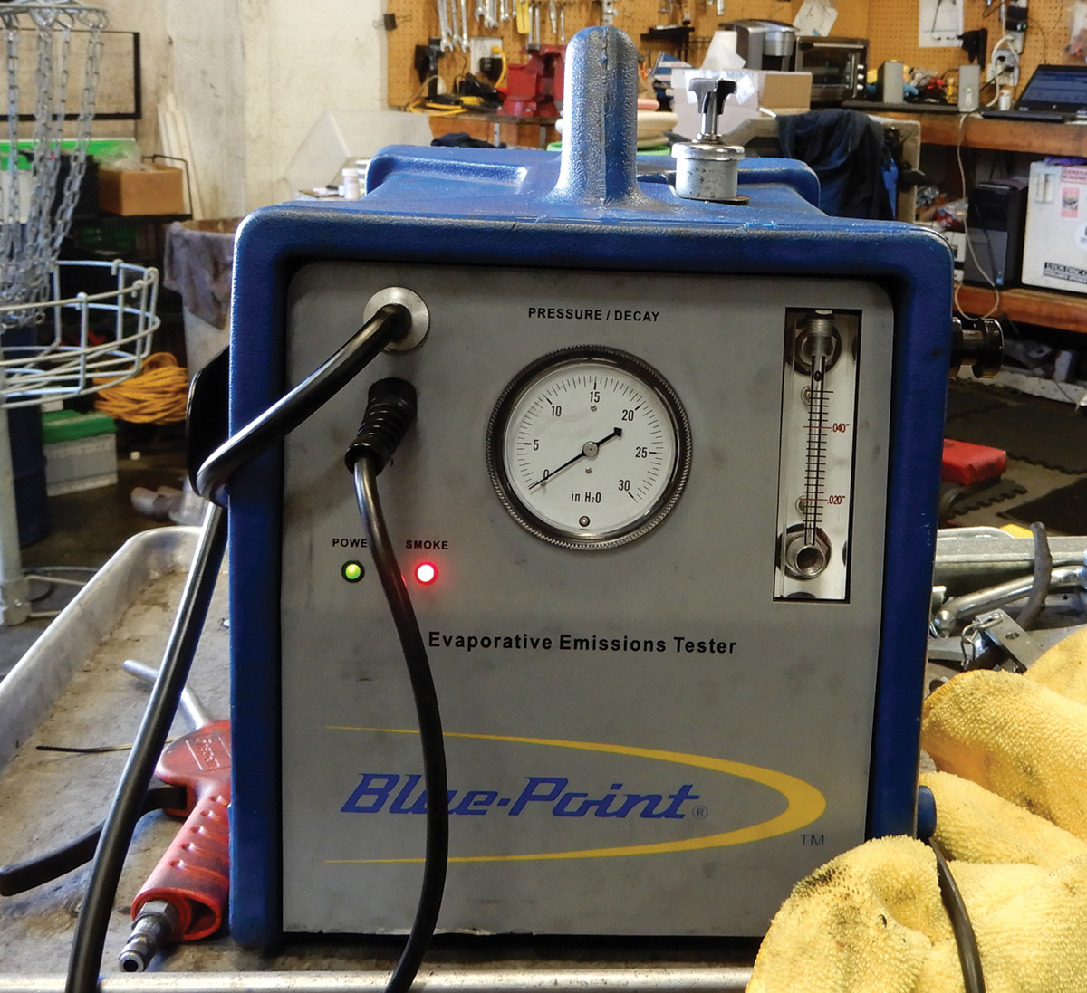
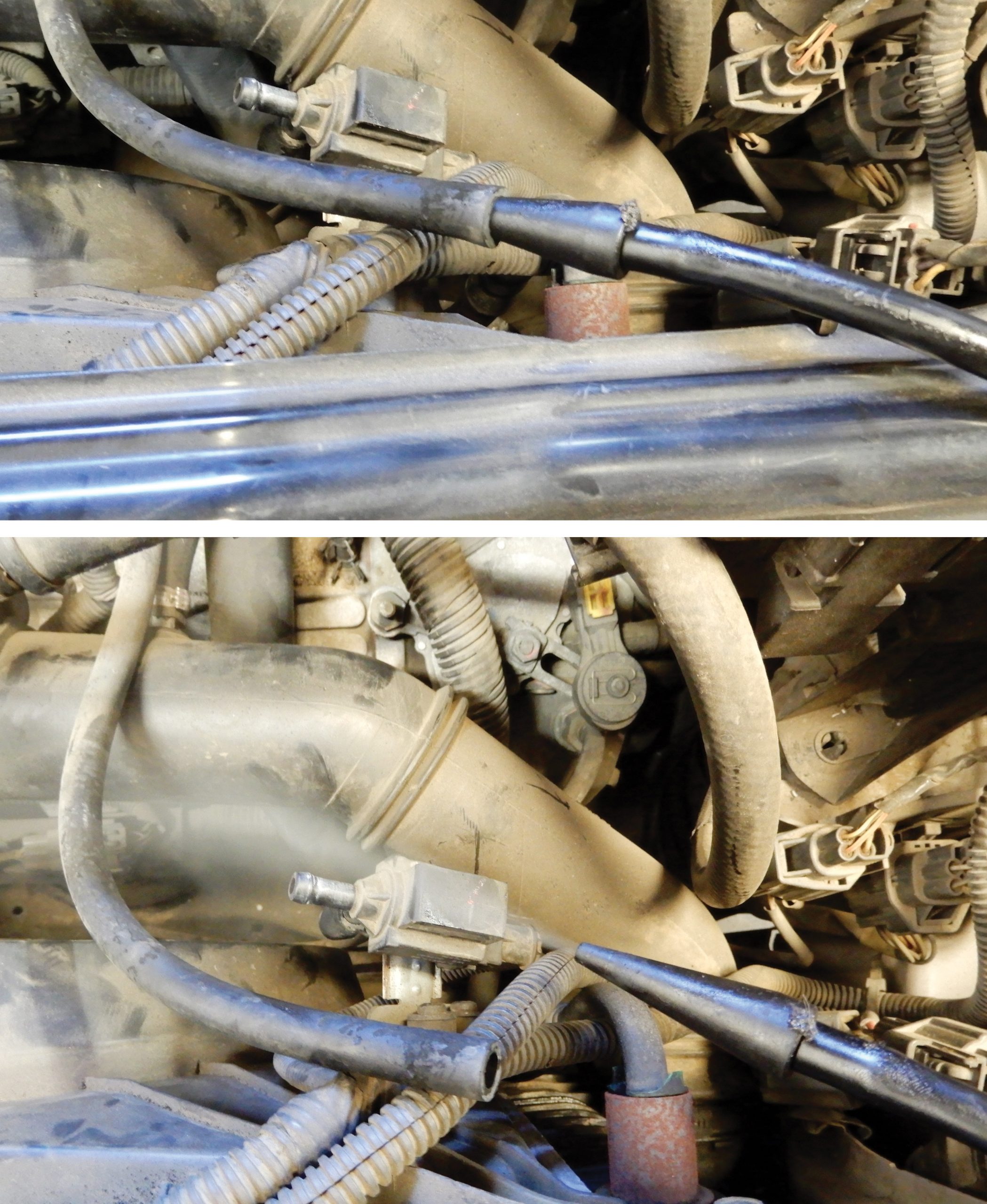
Smoke testing or introducing smoke into the system can help in finding EVAP leaks, possible hose leaks, or maybe a faulty seal at the tank. Hoses at the EVAP canister deteriorate, get worn out and crack, letting vapors out and setting a Check Engine light.
Volvo 850 Fuel Pump Replacement
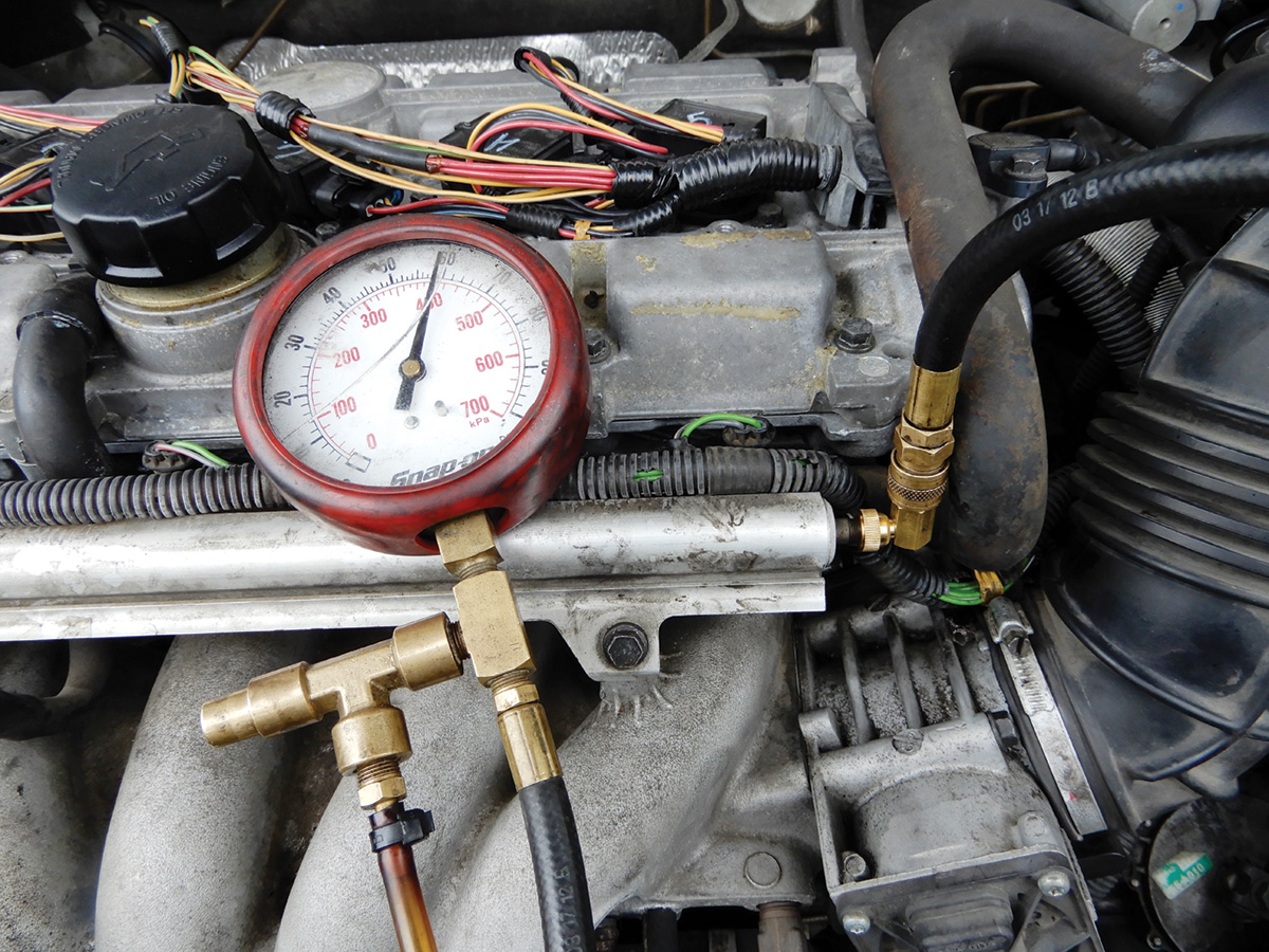
Now that diagnosis has determined that the fuel pump is not working, make sure to disconnect the battery negative cable before beginning repairs. Relieve all pressure in the system. This can be done at the Schraeder valve on the fuel rail. Hook up a fuel pressure test gauge to relieve pressure and catch all fuel in a drip pan. Now that all pressure in the system is relieved, replacing the pump will be a cleaner and safer job.
Lower the right rear seat. This will give room to replace the fuel pump. Open the trunk and remove carpeting to expose the fuel pump cover. Disconnect all electrical wires that lead into the pump. Remove the cover bolts with 10 mm heads. Now that the cover is off, carefully disconnect the two quick connect fuel lines that are connected to the fuel pump.
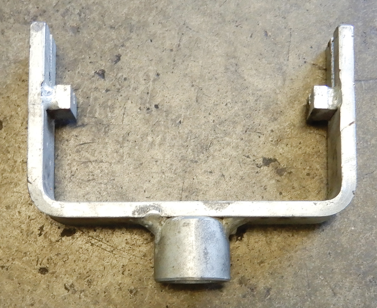
Remove the collar using tool number 9995485. Pull out fuel slowly so as not to spill fuel everywhere. Install a new fuel pump, Volvo Genuine Part number 9480152. If the fuel pump is out for a time, make sure to temporarily install the collar. Otherwise, the fuel tank could expand due to the characteristics of the plastic tank.
After the new pump is installed, torque down the collar to 30 ft-lbs or 41 Nm. Connect both the pressure and return lines, making sure to connect correctly. Attach electrical connectors. Before buttoning up everything, connect the battery and start the vehicle, making sure there are no leaks and that the pressure is at the correct reading. Install the cover over the fuel pump assembly and install the carpet.
Diagnosing When No Check Engine Light is Present
Diagnosing fuel problems can sometimes be tricky. Suppose a customer comes in with a 2006 XC90 with no Check Engine light but with the customer saying the vehicle doesn’t have the same pickup as it used to. Well, of course the first check will be to verify fuel pressure.
This is a good time to utilize VIDA. Connect VIDA to the vehicle using DICE. Once the connection is secure, go to Vehicle Communication and select Engine Control Module. Go to Monitoring Systems Parameters and check fuel pressure. Fuel pressure should be approximately 400 kPa.
Idle the vehicle and check fuel pressure. Increase RPMs and continue to monitor fuel pressure. Does pressure stay the same? Test drive the vehicle while hooked up to VIDA, and see if pressure is the same under load. If not, and if pressure becomes erratic, but at idle the pressure is fine, the problem could be the fuel pressure sensor that is connected at the fuel rail.
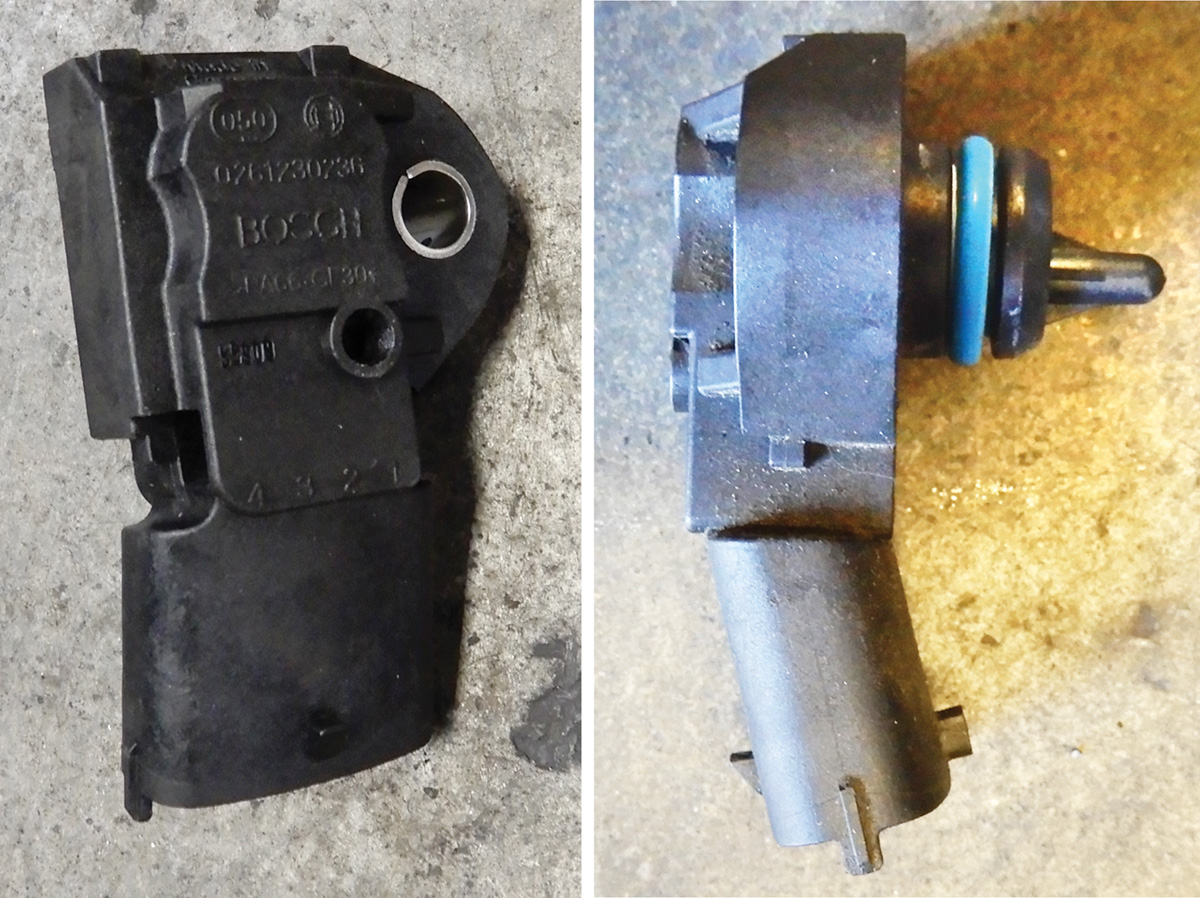
Replace the fuel pressure sensor with Volvo Genuine Part number 31272730. Using a T25 Torx socket and ratchet, unscrew and remove the sensor. Put a rag around the sensor area to capture escaping fuel. Install a new fuel pressure sensor making sure not to damage the O-ring and tighten down. Attach the electrical connector and start the vehicle.
Monitor the system again with VIDA. Is fuel pressure OK at idle? How about while driving under a load? If fuel pressure reads good and the vehicle runs well, mission accomplished.
Consult TJ 32739 for Volvo fuel pump issues.
On certain models, Volvo had a recall because of a fuel smell and possible fuel leakage. This includes the 2001 to 2005 S80, the 2001 to 2004 V70, S60 and XC70, and the 2003 to 2005 XC90.
These vehicles would be inspected at your local dealer. The fuel pump would have to be exposed, and if the fuel pump is leaking for any reason, the fuel pump would be replaced at no charge to the customer.
Remember, the smell of raw fuel can always present the hazard of fire in your shop or at the customer’s home or place of business. So, always advise your customers to be safe and call you for a tow to your shop any time they smell raw fuel.
Replacing fuel pump in a Volvo XC90 2005
Once you know the fuel pump is the problem, the fuel gauge has been hooked up to Schraeder valve at injector rail and confirms no fuel pressure, check to make sure there is power and ground at fuel pump. Now to replace the fuel pump.
First off, we will need to drain some of the fuel out of the tank. This can be done by inserting a hose into the fuel filler pipe and using a suction device to extract fuel from the fuel tank. Depending on how much is in the fuel tank, remove as much as possible into a fuel container.
Pull up the rear seat bottoms and remove the bolts and take the seats out of the vehicle. Fold back the carpet and expose both the fuel level sensor which is on the left side, and the fuel pump assembly on the right side. Remove the covers over the fuel pump and level sensor. These are 10 mm small bolts. Mark both the fuel pump assembly and the level sensor. That way, both will go back together correctly.
Clean all debris, and blow out around both the fuel pump assembly and the fuel level sensor so debris doesn’t fall into the fuel tank. Disconnect the electrical connector and hoses at the fuel pump. Disconnect the electrical connector at the level sensor.
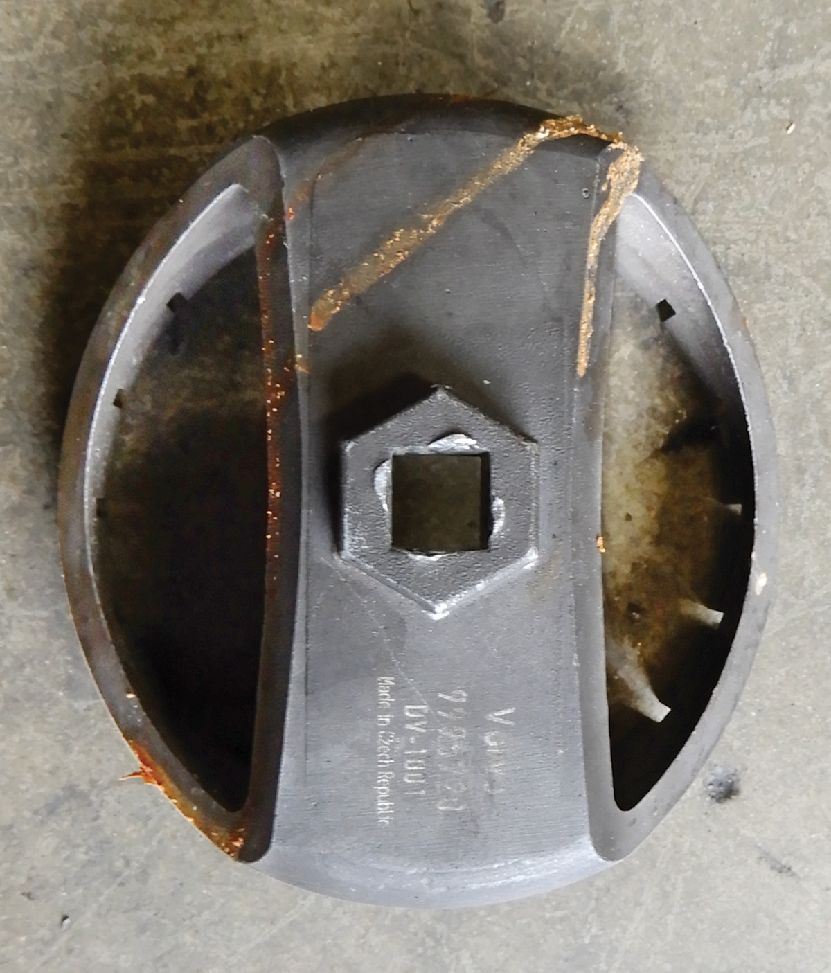
Using special Volvo tool number 9995720, remove the plastic collar around the fuel level sensor.
Pull out the level sensor, being careful not to bend or damage the float. Disconnect the line going back into the tank at the level sensor. Connect some wire to the area that was disconnected at the level sensor. Make sure the wire is long enough to pull through the tank and out from the fuel pump side.
Remove the collar around the fuel pump and pull out slowly, catching any escaping fuel with a rag. Pull completely out, and pull wires from the other side. Connect the wire to the new pump wire and pull the wire back through to the left side of the tank, making sure the fuel pump assembly is in the correct position.
Screw the collar back on at the fuel pump side and tighten to 60 Nm. Attach the electrical connector and fuel lines making sure all are secure.
On the left side, remove the wire that was tied on that ran through the tank. Connect the level sensor and its electrical connector and insert it into the fuel tank, making sure to line it up correctly. Tighten the collar nut. Add fuel to the tank and start the engine, making sure there are no fuel leaks of any kind.
Install the covers over the fuel pump assembly and the level sensor. Lay the carpet back into place and install the seats, then tighten down. Test drive the vehicle, making sure performance is at its peak.


0 Comments