

Volvo interior electrical systems are based on a network with a number of modules. We will talk about different Volvo interior electrical systems, what they do, and how to diagnose them using VIDA. We’ll also discuss how to diagnose early models without VIDA.
In the 1990s, there were few interior electrical systems. Lights, including dome light, interior lights, instrument panel, electric windows and locks, and alarm systems, and that was about it. These systems were pretty simple and straightforward. Any time there was a problem, the first thing to do was to check the fuses and/or bulbs if one was out. These systems were all 12 volt systems and could be checked out with a test light or volt meter.
These systems from the 1990s were also equipped with relays which also could be a problem. To check these systems without taking everything apart, you could expose the switch and check power and ground to the switch and operate the switch to see if it was working correctly.
Being able to read a wiring diagram and use a meter is a definite plus for locating and repairing electrical problems in older Volvo vehicles and even now in the present.
With the help of VIDA, locating components, reading out codes, and activating components will help in diagnosing problems with interior equipment.
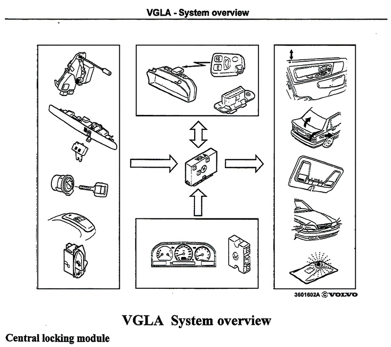
Let’s talk about the Volvo Guard Lock and Alarm system (VGLA) in the 1998 to 2000 S70s and V70s. This system has a control module that is equipped with software and hardware to control the lock system and alarm functions. The system is also integrated into the lighting system in the vehicle.
This control module could be changed to add and remove vehicle keys and remotes that would match the vehicle’s VIN.
There are different VGLA designs:
- Central locking system and alarm
- Central locking is standard in all these vehicles.
- The alarm system is optional depending on the market.
- The different markets determine which functions and components are installed in each vehicle. The alarm can be activated or deactivated using the remote or the key.
- Remote Control
- A remote control is standard on all vehicles with alarm systems. In vehicles with only central locking, the remote control is optional.
- The remote control receiver works on different frequencies. The remote control works up to 15 to 30 feet. Separate buttons can lock and unlock the doors and the trunk or tailgate in the vehicle. Some remotes have a panic button that will set off the alarm when pushed.
- Type of locking systems
- There are two different locking systems – a one-stage system and a two-stage system. These systems may be programmed either way.
- Internal switches
- There are switches in the doors and trunk or tailgate for locking and unlocking this system.
- There is a switch in the driver’s door to unlock the trunk or tailgate and the fuel door latch.
Component Input Signals
- Door switches signal if doors are open or closed.
- Lock switch in driver’s door. The locking latch has a micro switch built in and is operated by the key lock cylinder. Locking and unlocking request comes from the central locking system.
- The trunk or tailgate utilizes the same kind of micro switch for locking and unlocking.
- The ignition switch signals if the key is in the lock or not. This would be the S connection at the switch. The signal if the ignition is on or off is the +15 connection at the switch.
- There is an internal switch in the fuel door latch to open the fuel door.
- The speedometer prevents the trunk from coming open when activating the switch at over three mph.
Component Two-way Signal
- The receiver has a built-in antenna and is mounted on top of the instrument cluster for good reception.
The receiver receives control signals from the VGLA control module:
- Sends a signal to the VGLA for the remote control
- Changes the radio signal to a digital signal from the remote control to the VGLA control module
- The remote has a unique code for each button.
This control module sends signals to locking motors in the doors and trunk or tailgate. Depending on the locking system, the control module transmits different signals to the central locking motors. The signal can lock or unlock each door and trunk or tailgate.
Alarm Module
- Vehicles with alarms have remote controls to arm and disarm the alarm system. This system monitors the doors, trunk and/or tailgate, hood, and horn or siren.
Component Input Signals
- Hood switch, a micro switch inside the lock mechanism
- Glass break sensor, by the glove compartment near the speaker
- Level sensor, in case vehicle is being towed away
- Metal wire sensor in rear window. In case it is broken the alarm will sound.
The sunroof has been used in Volvos for many years, and the systems have changed from the old mechanical crank system to the new power laminated panoramic roof.
Sunroofs can be quite complicated in troubleshooting and repairing. Having two sides with gates and cables, they must be synchronized so that the roof mechanism will move smoothly and all positions work correctly.
When sunroofs became electric, the sunroof motor was located above the rear view mirror. It was mounted with the gear side inserted into the two cables that would open and close the sunroof.
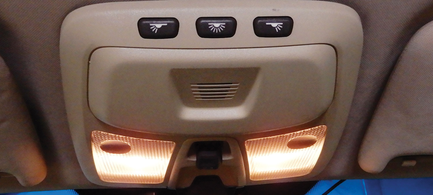
The button that controls the sunroof is located in the dash for the older models and in the dome light assembly on the newer models. Pushing the button back will open the sunroof. Pushing the button the other way will close the sunroof. Pushing the button up will tilt the back of the sunroof open.
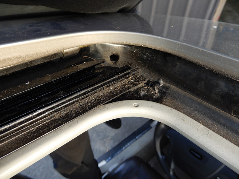
Usually the problem with sunroofs not opening correctly is cables that wear out and become flat. When this happens, the motor can jump some teeth, making the sunroof off center. Replacing the sunroof cables and gates can fix this problem.
To replace the cables and gates takes some time, and sometimes you will need to take the complete sunroof tray out of the vehicle to repair it. This means taking out the headliner. This can be quite tricky, so it’s a good idea to use VIDA to understand how to accomplish this task.
Maintaining the sunroof is key to making it work properly all the time. Blowing out all the debris while the sunroof is open and cleaning out the drains will help in maintaining a good working sunroof. Lubricating the sunroof gates and tracks with a dry lube works well.
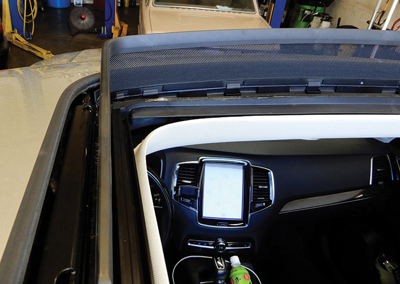
The newer model power laminated panoramic roof is a glass roof divided into two sections. The front section is opened by sliding up and over the rear section that is stabilized. The front section can also tilt up at the rear edge for ventilation. There is also an electrically controlled roller sunshade between the laminated panoramic roof and the headlining made from perforated fabric.
The basic function is quite similar to other Volvo sunroofs. The switch is located in the upper roof panel. The motor opens and closes the roof with cables and gates.
The sunroof has a sunshade that’s mounted at the back of the sunroof tray. The sunshade is also operated by the switch and can be opened to any position.
The laminated panoramic roof has a pinch protection system that reduces the risk of closing on a small object or possibly your hand. The system works when anything is blocking the movement of the roof or shade.
A wind deflector at the front of the sunroof pops up when sunroof is opened and back down when closed. The wind deflector helps guide air into the cabin and also helps to reduce noise.
The Power Seat Memory and Function
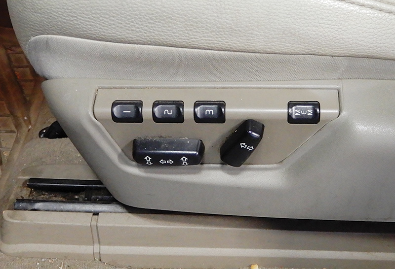
Volvo has been using power seats since the 1980s. Power seats basically move the seat into position for any driver. The memory function adjusts the seat for different drivers. Each driver can press one of the memory buttons that is programmed for them to adjust the seat to fit them.
The power seats can be adjusted when the key is in position 1 or 2.
During a ten-minute period after the doors have been unlocked, if the door remains open and if the door is closed and the ignition key is not yet in the ignition, or if key is in the ignition but still in position 0, the seat can be adjusted within forty seconds. The passenger seat can only be adjusted if the ignition is in position 1 or 2 or the vehicle is running.
The power seats do have an override protection system that senses anything blocking the seats’ operation. If this happens, turn the ignition off and wait twenty seconds before operating the seat again.
Depending on the model and year, there are three different memory buttons to program the seat. To program the seat, adjust it to the desired position. Press down the memory button, and while holding the button down, hold down position 1, 2, or 3. To move the seat to the desired position, push the appropriate number and hold it down until the seat is in position. If you let off the button, the seat will stop.
The remote control can also be equipped with an option function that controls the driver’s seat. After you have adjusted the seat to the desired position and turn off vehicle, lock it using the remote control. When you return and unlock the car, the driver’s door seat will automatically adjust to the preferred position. If there is more than one remote, depending which remote is used, the seat will adjust to that remote’s setting.
Hydraulic Power Tailgate
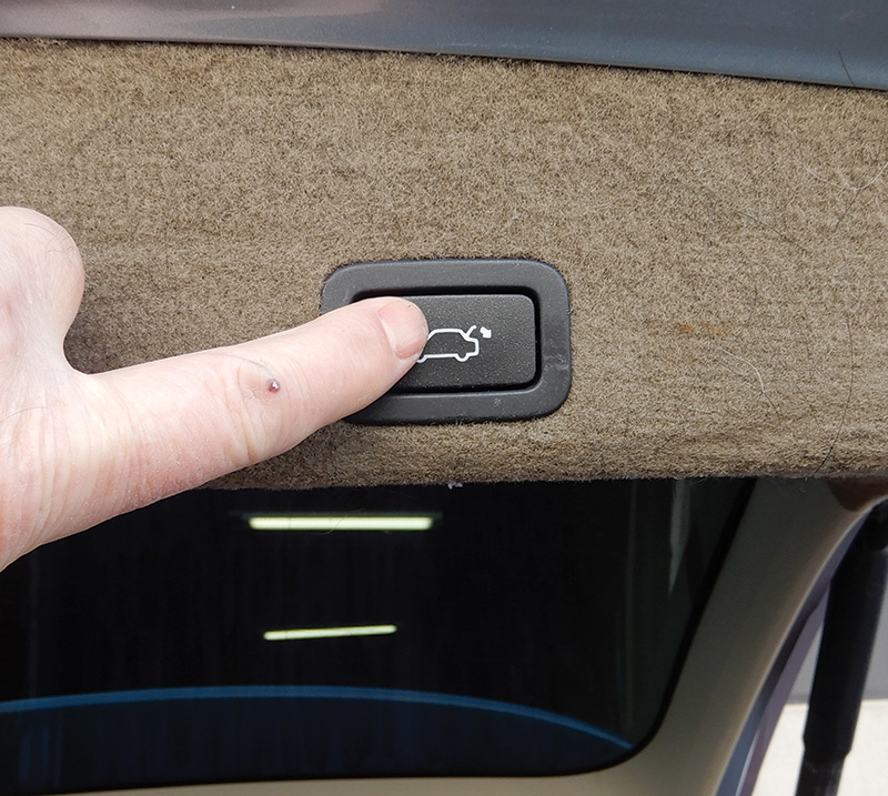
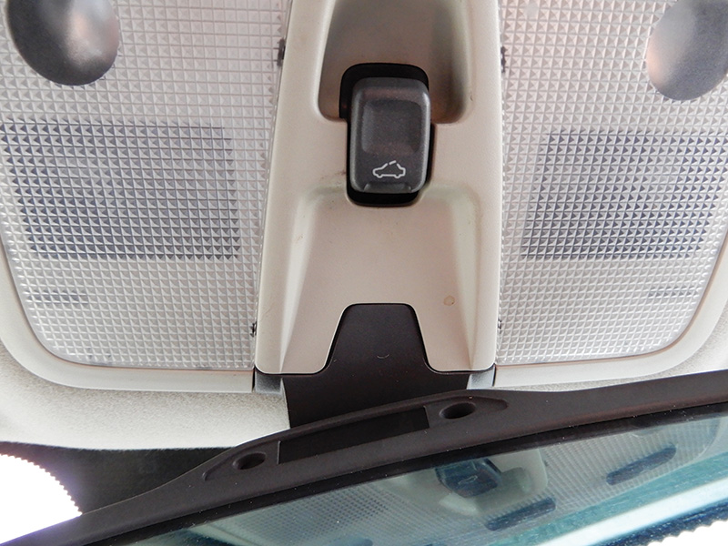
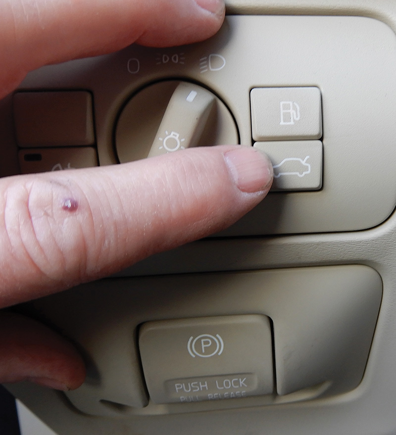
The 2008 to 2010 V70 and XC70 could be equipped with a hydraulic power tailgate. To open the tailgate, there are three options. One, by pressing the button on the remote control and holding it for 1.5 seconds. Two, by pressing the button inside the cabin located in the light switch assembly and holding it for 1.5 seconds. Or three, by pressing the tailgate outer handle if the vehicle is not locked. When the tailgate is open, you can press the button on the tailgate to close the tailgate.
When the tailgate is open, a message will be displayed on the Driver’s Information Module (DIM), and the rear interior light will be on with the rear position lights. The tailgate cannot be opened or closed while the vehicle is in motion.
The power tailgate consists of these components:
- The inner switch located at the light switch
- The anti-pinch sensors located at the track of the tailgate
- The open and close motor located inside the tailgate
- The closing switch located in the tailgate
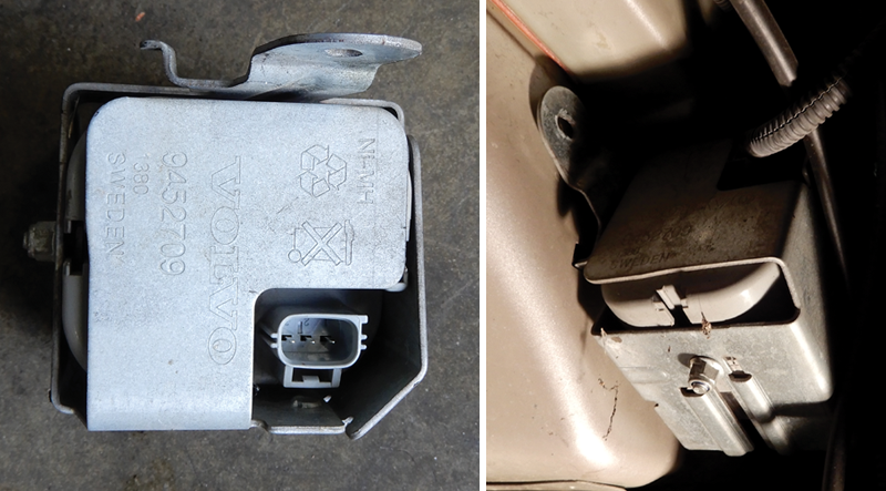
- The fully open sensor located in the opening motor; the first locking position sensor, located in the opening motor; the load sensor located at the hydraulic pump
- The outside switch located in the handle
- The control module and hydraulic pump, located in the tailgate
- The remote control.
The power tailgate consists of a hydraulic pressure system, which opens and closes the tailgate, and two electric motors — one for releasing the tailgate before opening and one for latching the tailgate.
When opening the tailgate, an electric motor releases the tailgate latch to enable hydraulic opening. Hydraulic oil is then pumped from the reservoir to the hydraulic pump to open the tailgate. Closing the tailgate, hydraulic oil is pumped from the reservoir to the pump and the tailgate retracts.
When the sensor determines the tailgate is at the latch, an electric motor then pulls the tailgate to a latched position assisted by a cable. When the sensor indicates the tailgate is latched, the electric motor is reversed to reset the position of the cable to prepare for the next opening of the tailgate.
Fault Tracing Common Electrical Circuit Problems
Check for open circuits. An open circuit is a break in the path of current flow. In a parallel circuit, a break in the circuit will result in a fault in a particular component. An open circuit in a series of circuits will cause the complete circuit to malfunction. Always check connections for oxidation or possible loose connections. You can use a volt meter to check wire connections. Disconnect connectors and check resistance by pulling or shaking wires. The ohmmeter should read approximately zero.
A short circuit to ground is usually broken or frayed wire insulation. The wire could touch ground and make a fuse blow. Using a circuit breaker tool in place of a fuse can help so you don’t keep blowing fuses.
Disconnect each component in the circuit and check for the circuit breaker to pop. If the circuit breaker doesn’t pop, it’s quite likely that the component that was disconnected could be the problem. After locating the problem, make sure to remove the circuit breaker and replace the fuse. Check to make sure everything works correctly.
A short circuit to supply voltage occurs when wires are frayed or broken and interrupts another circuit. This can cause both circuits to work intermittently or incorrectly. First look at the circuit not operating correctly, and try to identify the problem. Being able to use and read a wiring diagram and learning how the circuit should operate is key to finding the problem.
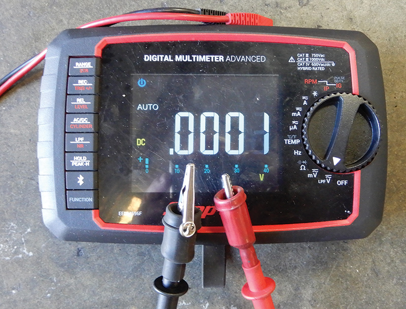
Check for high circuit resistance conditions. Checking the voltage drop in a circuit will check for high resistance when the circuit is operating. Voltage drop is the amount of voltage required to push the current through a specific resistance. By placing the meter leads at each end of the resistance, you can measure the voltage drop caused by that resistance.
For instance, measure the voltage drop in the positive battery cable that looks to have corrosion at one end of the cable. You can measure the voltage drop caused by the resistance. As the resistance increases, voltage drop increases.
Below are a few terminal designations on a Volvo with standard labeling.
| 1 | Ignition coil, ignition distributor negative side |
| 15 (15R) | Switched battery positive, power in key positions 2 and 3 |
| 15i | Switched battery positive, power in key position 2 |
| 30 | Direct battery positive |
| 31 | Ground |
| 50 | Starter solenoid fee |
| 85 | Actuator winding of a relay, usually ground |
| 86 | Actuator winding of a relay, usually supplied with voltage |
| 87 | Activated output of a relay (87A = second output) |
| B+ | Battery positive |
| D+/61 | Alternator or generator charging light |
| X | Accessory feed, power in key position 1 and 2 |


0 Comments