

The Volvo 5 cylinder engine has been the workhorse engine for many years, starting in 1993 with the 850 model in the U.S. The 850 went away in 1997 with the introduction of the S70 and V70 in 1998 and the XC70 in 1999.
Volvo continued using this 5 cylinder engine until 2014 in the S60, and they then went back to the 4 cylinder engines. This article will address sealing the valve cover on the 5 cylinder engine, what to look for, and what tools to use to make this job complete.
The 5 cylinder engine started with the Volvo 850. This model was pretty simple with two mounted sprockets at the front camshafts, no Variable Valve Timing (VVT) units, and no solenoids or coil packs. Basic spark plug wires and distributor cap that could be set aside make this model a little easier on which to seal the valve cover.
As the engine changed through the years, adding coil packs to each cylinder, VVT units and VVT solenoids with electrical connectors made for a little more involvement to reseal the valve cover.
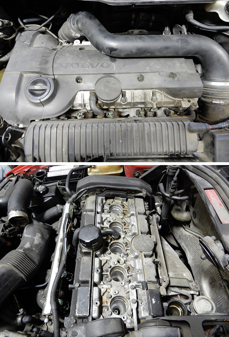
As the years go by, the valve cover will start to leak and will need to be sealed again. One cause of valve cover leakage is the oil trap which gets clogged up and the engine cannot breathe. In turn, pressure builds up inside the engine and pushes the oil out in its most vulnerable spot, which sometimes is the valve cover and/or cam seals.
Make sure the oil trap and all hoses are free of clogged debris. Make sure to check the pressure in the engine and, if the oil trap is plugged, be sure to replace it and clean out the passages into engine. Proper maintenance, including changing the oil when it’s time, can help prevent build-up inside the engine and will make the vehicle last longer.
These valve covers don’t have a regular gasket but rather have a chemical gasket that is used to bond the valve cover to the cylinder head once everything is bolted together.
Through the years a few things have changed with this engine, but doing this job is primarily the same with all of the 5 cylinder engines.
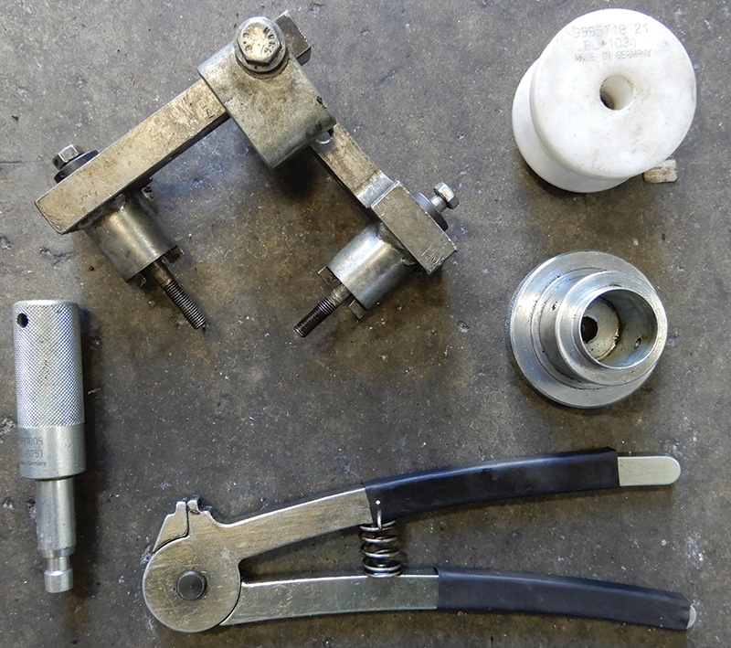
Tool 9995670 is used to lift the valve cover from the cylinder head. Tool 9995451 is the crankshaft stop tool. Volvo tool 9512767 is a roller to apply liquid gasket during assembly. 9995450 is the press tool for the rear camshaft seal. 9995718 and 9995719 are special tools to press in the camshaft seal at the front of the engine.
After confirming an oil leak at the valve cover, now it’s time to disassemble. Disconnect the battery and drain the coolant from the vehicle. Disconnect the small hose at the expansion tank and lift up the expansion tank while removing the connector for the level sensor. Disconnect the big hose and remove the expansion tank from the vehicle.
Lift the power steering reservoir up and over the valve cover and let sit until the timing belt assembly is removed. Remove the auxiliary belt. Remove the front engine cover from the engine and set aside. Remove the front right tire and remove the nuts that hold the inner fender in place to expose the crankshaft nut. Spin the engine over at the crankshaft until the timing marks are aligned properly.
Remove the air cleaner assembly by disconnecting the hose clamp at the air mass meter and disconnecting the air inlet hose. Some models will have the turbo boost valve connected to the air cleaner housing, so this will need to be disconnected also. Now pull up on the housing and remove it from the vehicle. Remove the top stabilizer brace that is mounted at the strut towers.
The hose that was just disconnected at the air mass meter, you can now disconnect it at the turbo and remove the other connecting hoses and electrical connectors. Remove them from the vehicle and set aside.
The hard turbo pipe from the intercooler to the top of the turbo will need to be removed. Make sure to check to see if the intercooler hose is oil soaked and, if so, replace it during reassembly.
Remove the plastic cover over the spark plugs. Remove all coils over the spark plugs and number them so you can remember their location during reassembly.
Disconnect the ground wires and, with the coils still connected to the electrical connectors, pull the coils off and set them onto the transmission out of the way. Remove the wire connector at the VVT solenoid. The crankcase ventilation hose will need to be disconnected at the top of the valve cover.
Remove the cover from over the injectors. This cover may be plastic or metal depending on the year of the vehicle. Remove the two 10 mm bolts that hold down injector rails and pull the injector rail straight up and set it out of the way. This will give room to seal the valve cover.
Remove the top engine mount and cam sensor housings from the rear of the engine at the back of the camshafts. This will expose the rear of camshafts so you can install special tool number 9995452.
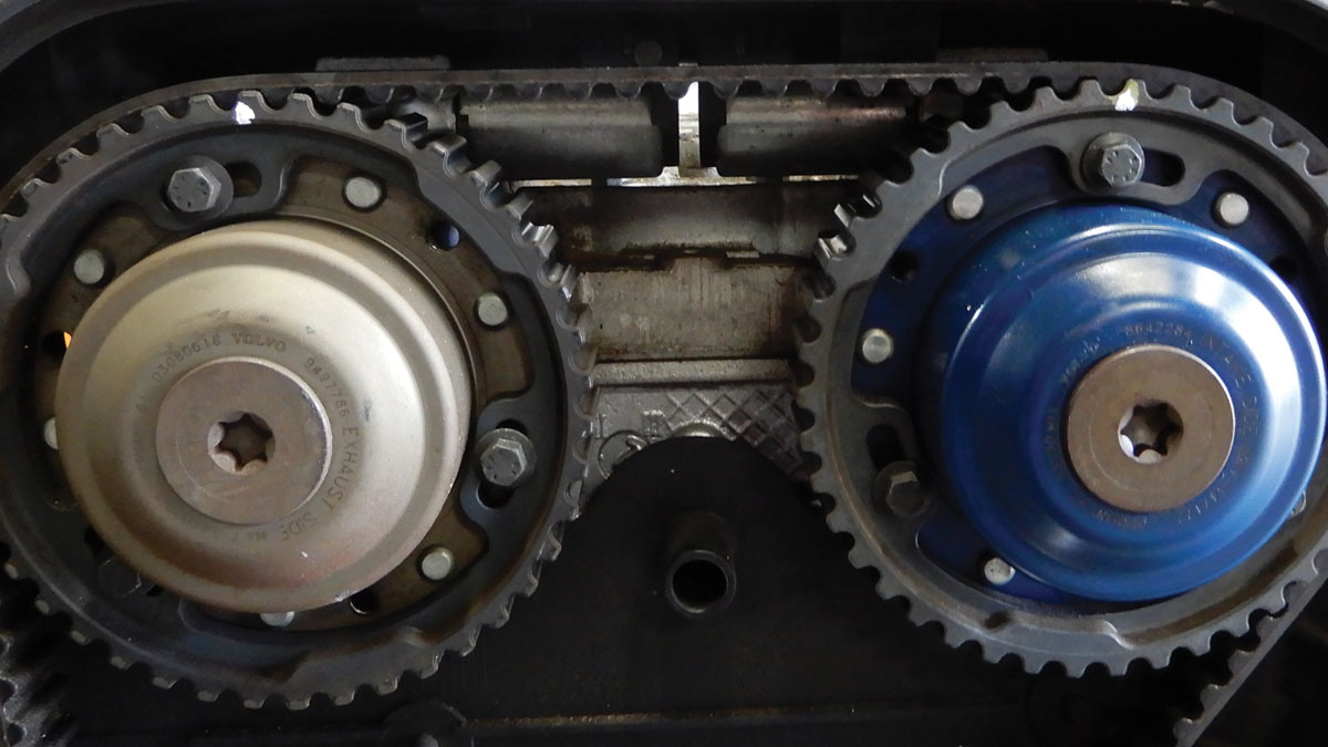
Remove the front cam sprockets and VVT unit bolts with a Torx T55 tool. Use a rag when removing the center bolt at the VVT unit to absorb oil coming out of the unit.
Now that the VVT bolts are loose, unbolt the timing belt tensioner and remove the timing belt. Now remove the front sprockets and VVT unit, if equipped, and set aside. Before removing the VVT unit check for lateral play; if there is any, be sure to replace the unit with a genuine Volvo part.
Remove the VVT solenoids, depending on year and model. Install the special tool in number 1 and 5 cylinders, tool number 9995454. Tighten down and leave about a 2-3 mm gap at the valve cover.
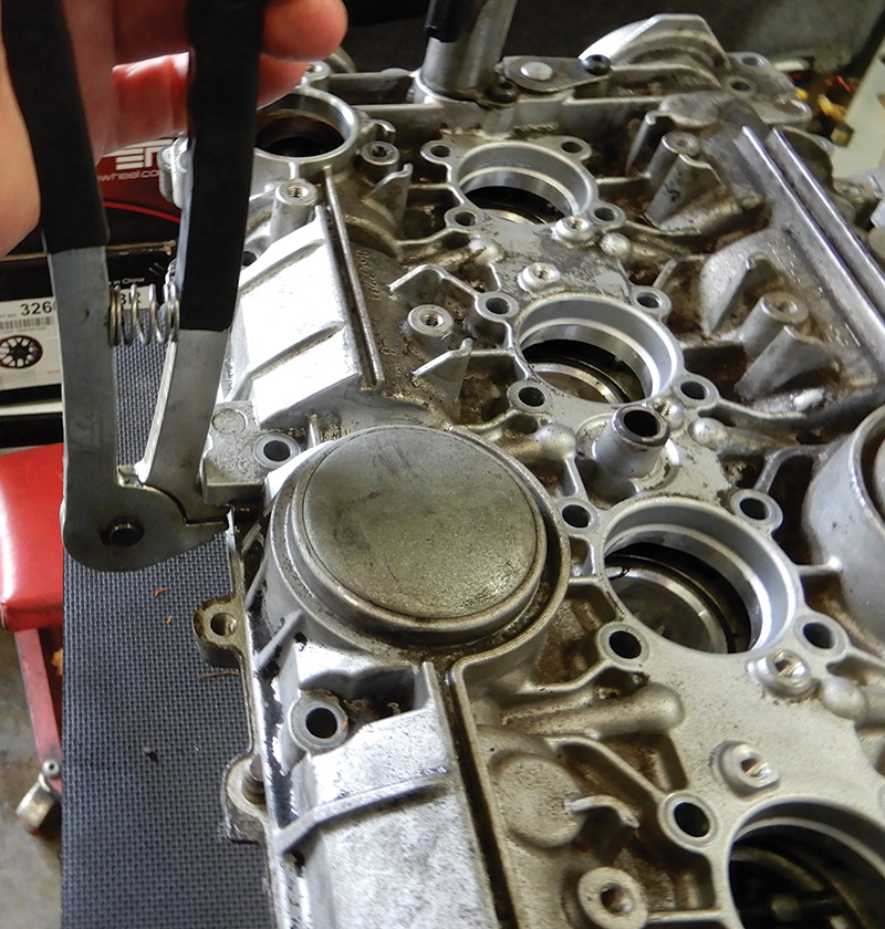
Remove all bolts securing the valve cover to the cylinder head. Once all bolts are removed, use the special tool pliers to break loose the valve cover from the head. Apply pliers around the valve cover in different locations, and slacken off the wing nuts on special tool 9995454, little by little, until the valve cover is separated from the cylinder head.
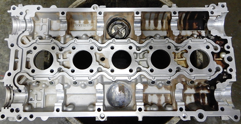
Remove the valve cover with camshafts, and set the camshafts aside. Inspect all parts and camshafts for any problems.
Now clean all parts, including bolts and nuts, for reassembly. Use a gasket scraper and/or razor blade with solvent, part number 1161440, to clean off the valve cover and the cylinder head. Clean all debris from the cylinder head and blow it out with air to get all particles removed. Using a spray solvent works well. Be sure to clean in a well ventilated area and try to not breathe fumes.
Make sure to check all bolt hole threads in the cylinder head. Being aluminum, the threads can sometimes pull out with the bolt during disassembly. In this case, you may be able to save the threads with a thread chasing tap, and if no threads are left, you will have to install a threaded insert.
Now that the cylinder head and valve cover are cleaned and ready to be assembled, make sure all lifters are in place and clean. Since we didn’t replace the cylinder head, the valve adjustment will be fine. Lubricate the valve lifters keeping the surface for the valve cover clean.
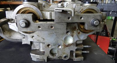
Set the exhaust camshaft into place on the cylinder head with the back of the camshaft below an imaginary center line. Set the intake camshaft into place with the back of camshaft above an imaginary center line. Setting the camshafts in with tool 9995452 attached to the rear of the camshafts will also work when installing the camshafts.
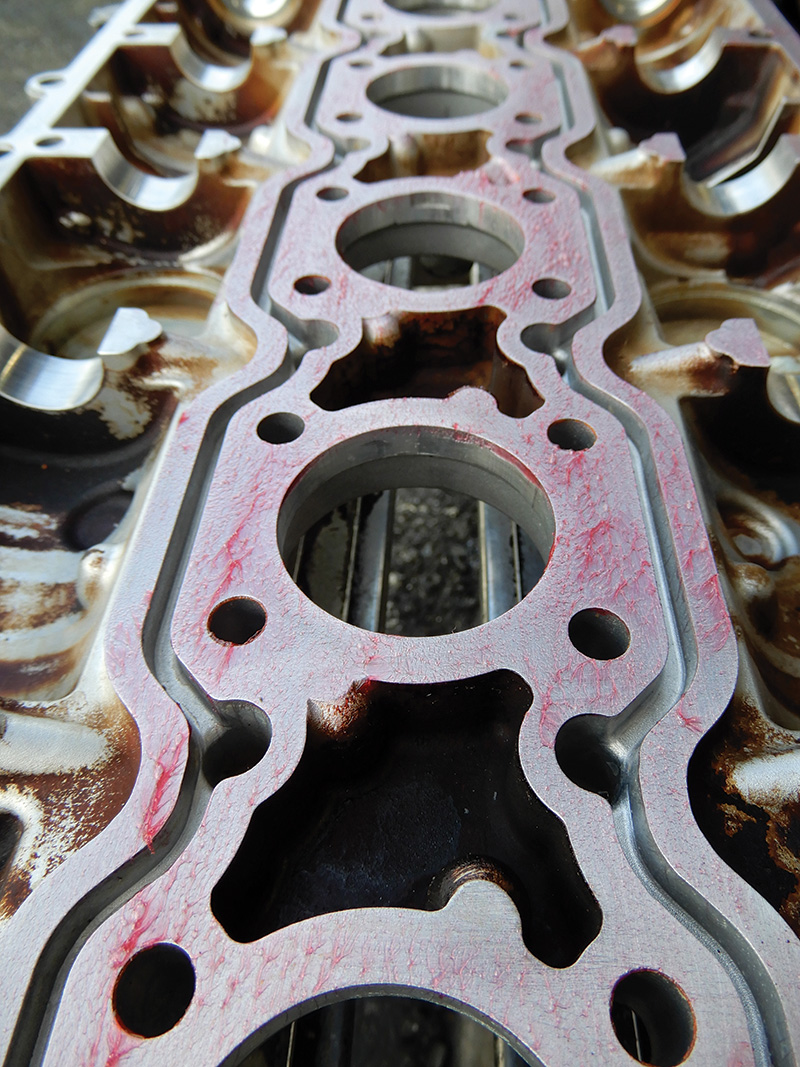
Install new o-rings at the spark plug wells on the cylinder head, making sure to set them in the grooves. Now, on the valve cover itself, apply liquid gasket Volvo part number 1161059. Using roller special tool 9512767, apply liquid gasket, making sure the complete valve cover is covered. Be sure not to let the liquid gasket end up in the oil channels.
Lubricate the camshaft lobes, the valve lifters, and bearing surfaces. Set the valve cover into place and install tool 9995454 into spark plug holes 1 and 5. Tighten the press tool down, keeping the valve cover parallel to the cylinder head until flush. Install the valve cover bolts and slightly tighten them down starting from the middle going out. Once all bolts are in, remove the press tool. Using a torque wrench, torque down the valve cover to 17 Nm. Be sure to check year and model; torque could be slightly different.
Install the tool at the back of the camshafts if not already done. This will align the camshafts to be in the top dead center position. Install new front camshaft seals using special tools 9995718 and 9995719. Lubricate the surface on the inside part of the seal that rides on the camshaft. Using the tool, press the seals into place, using the bolts that hold the VVT unit and sprocket in place.
Install new gaskets for the VVT solenoids that sit on top of the valve cover. Install and adjust the VVT unit or units onto the front of the camshafts. Secure the center bolt but don’t tighten completely. Install the sprocket gear onto VVT unit, leaving all three bolts loose for now, and try to align the timing marks so that they are within two sprocket cogs or teeth. This can be adjusted and tightened when the belt is installed.
Set the other camshaft up the same way, or just install the sprocket gear with timing marks aligned, again leaving three bolts loose to be tightened after the belt is on. This would be a good time to replace the timing belt and water pump if needed.
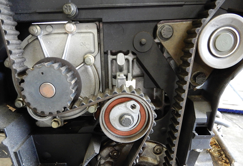
Route the timing belt under the crankshaft pulley and up to the intake camshaft sprocket, around the sprocket, and over to exhaust gear VVT variable valve timing unit, around water pump and over to the tensioner. Leave the tensioner loose so as to push the tensioner so that the timing belt can be installed around the tensioner. Use a 6 mm allen wrench to adjust the tensioner into the correct position.
Tighten the front camshaft sprockets and VVT unit(s) to specs. Remove the tool above the starter and install the starter back into place. Connect the electrical wire if disconnected. Remove the special tool at the rear of the camshafts. With a 30 mm socket and ratchet at the front of the crankshaft, turn the engine over a couple of times and make sure the timing marks are aligned perfectly.
Clean the rear camshaft journal with emery cloth so that the seal mating surface is clean of any contaminants. Using special tool number 9995450, lubricate the seal inside surface and press into place.
Clean out the area that injectors sit in and blow out any debris. Set the injector rail into place and push down. Install two bolts at the rail and tighten down.
During this operation, if the oil trap is plugged or hasn’t been changed, this is a good time to address. By removing the intake manifold, the oil trap can be exposed.
Install the front timing cover and secure. Install the auxiliary belt and, if needed, replace with new genuine Volvo part. Set the expansion tank into place, connecting both upper and lower hoses. Secure the level sensor in the bottom of the expansion tank. Set the power steering reservoir into place.
On the back side of the engine, install the camshaft sensor housing and sensor. Depending on the year and model, there is a cam plug on some models. Install the top engine mount. Install the spark plugs and torque down. The coils and wires can now be installed in the appropriate positions, marked 1-5. Attach the electrical connectors to the camshaft solenoids and route so as to not get pinched from the cover. Secure the two ground wires. Set the plastic cover over the spark plugs and timing belt and tighten down.
Install the air charge hose going from the turbo to the air mass meter at the air cleaner. Attach the electric connector at the hose. Connect the other hoses in their appropriate places. Install the bracket at the back of the engine that covers the camshaft sensor housing. Connect the camshaft sensor electrical connector if not already done.
Set in the air cleaner box and snap it into place. If the mounts are worn out, be sure to replace them; this will keep the air box from sliding around. Install the air filter and top cover, securing to the air cleaner box. Connect the air charge hose to the air mass meter and tighten the clamp. Connect the air mass meter electrical connector.
Install the turbo pipe from the turbo to the bottom hose at the intercooler and tighten the clamps securely.
Connect the battery terminals. Add coolant to the vehicle and start the engine. Warm the vehicle up, letting all residue burn off the engine. Check the coolant level and top off. Install the top support bar from the strut towers and secure.
Test drive the vehicle and check all fluids again, making sure all are at the correct levels.


0 Comments