


We’ll cover the suspension systems through the years, how they have changed, what problems occur and how to remedy those problems.
Like all vehicles nowadays, the suspension has changed through the years and Volvo is no different.
In this article, we will go over the Volvo suspension systems through the years, how they have changed, what problems occur and how to remedy those problems.
Some common signs of suspension problems include:
- Pulling to one side when driving.
- Feeling every bump in the road.
- One side or corner sits low.
- Diving, rolling, and/or squatting, especially when sharp turning.
- Difficulty when steering. Steering becomes difficult, especially when driving at low speeds; this means that there might be a problem with the suspension or steering systems.
- Leaky or oily shock absorbers.
So now to diagnose these problems; this can sometimes be tricky, especially if more than one part is worn.
Pulling to one side could be a tire problem, or a worn out tie rod or ball joint. To check these problems, the best way is to raise the vehicle up on a hoist and move each front wheel back and forth to see if there is any play.
Volvo has some ball joints that are part of the control arm and others that are separate and are bolted into place.
To replace a ball joint on a S60 2001-2009, first remove the front tire. You will need to remove the bottom nut at the ball joint. If equipped with aluminum control arms, use a Torx bit to hold the center of the ball joint while removing the nut.
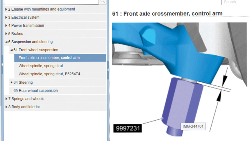
If the control arm is steel, remove the nut and use Volvo special tool 9997231 and screw it onto the ball joint, leaving 1.5 mm between the control arm and the tool. Now use tool 9997062 and fit it around the control arm and use special tool 9997231 to release the ball joint from the control arm.
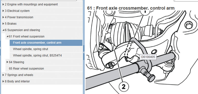
Now use Volvo special tool number 9997076 to pull down on the control arm to release the control arm from the ball joint.
Remove two bolts at the ball joint, and depending on which type of control arm you’re dealing with, use adapter special tool number 9997148 if aluminum, and if steel, use special tool adapter 9997230. Both will connect to slide hammer tool number 9992709 and will pop out the ball joint.
Clean the surface of the ball joint with a wire brush and install a new ball joint into place using guide pin tool number 9995781. If the control arm is aluminum, the guide tool will install with a wrench gripping at the bottom; if steel, turn the guide tool around with the wrench gripping at the top of the tool.
Tighten the guide tool securely and use tool number 9995796 to fit around the ball joint. Knock in the ball joint with a brass hammer, being careful not to damage anything. Install the two bolts and tighten down.
Use the special tool number 9997076 to pull down on the control arm to fit the ball joint into place. With an aluminum control arm, use tool number 9512927 to hold the ball joint into place so as not to damage the rubber boot and torque down to 50 Nm. For steel control arms, use tool number 9995467 to torque down the ball joint nut.
Install the tire and test drive. It’s always a good idea to do a wheel alignment after doing any suspension repairs.
Control arm bushings that are worn out can cause the front end to float around and when turning tight, feels like it’s over turning.
To replace control arm bushings, you will need to remove the control arms from the vehicle. To do this, you will need to remove the ball joint nut and remove the bolts through the sub frame to the control arms. To make this a little easier, use a scissors jack and lift the engine up a bit to expose the bolts at the sub frame and remove.
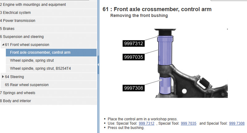
Once the control arms are removed from the vehicle, the old bushings will need to be pressed out and new ones pressed in. The tools to press out are Volvo tool number 9997312, 9997035 and 9997308. To press bushings in, use Volvo special tool number 9992852 and 9997308.
When installing front bushings in the control arms, make sure each bushing is in the correct position.
Correct position of bushing in control arm. Use tool 9995624 and 9997209 to press out the old rear bushing. For pressing the new bushing in, use the same tools as pressing out.
Make sure to do both sides when replacing bushings. Install control arms and, once again, its always a good idea to align the vehicle after any suspension repair.
Sub frame on Volvo
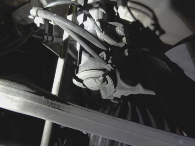
The sub frame on these vehicles consists of four mounting areas that have sub frame bushings. The four bushings through the years start to wear from all the weight and movement of the vehicle. To replace all four of these bushings, it might be a good idea to remove the sub frame from the vehicle.
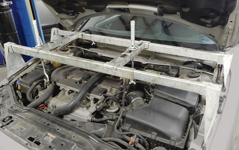
To do this, you will need a Volvo special tool to hold up the engine and transmission. This will be the first thing you will need to do.
Raise the vehicle in the air and remove the front wheels. Remove the bolts from all three engine mounts; also remove the bolts that hold the steering rack into place. Remove the nuts that hold the ball joint to the spindle. Disconnect the sway bar links. Remove the mount from the sub frame to the transmission. Remove the bracket at the exhaust at the rear of the sub frame.
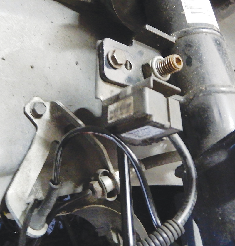
Position a transmission jack under the sub frame so that it won’t fall out. Remove the four sub frame bolts and the four bolts at the bracket at the rear of the sub frame. Start to lower the sub frame. Now you can disconnect the bracket at the oxygen sensors and set aside. On the front side of the sub frame, remove the screw that holds the electrical harness and the power steering hose bracket.
Use tie straps and hold the steering rack up so when the sub frame is lowered, the steering rack won’t be hanging.
Reinstallation
Lower the sub frame enough to be able to remove and replace the sub frame mounts. Once the sub frame mounts are replaced, you will need to lift the sub frame up and connect the bracket at the electrical wire harness and the bracket for oxygen sensors, making sure the oxygen sensor wires are not hitting against the exhaust.
Lift the sub frame up and set the steering rack into place. Insert the four sub frame bolts, making sure to align the ball joints, just to make the job a little easier and install the ball joint nuts and tighten.
Tighten the sub frame bolts and the four bolts at the bracket at the rear of the sub frame. These bolts are stretch bolts and need to be replaced and tightened correctly. Attach and tighten the exhaust bracket.
Install the nuts for the steering rack and tighten. Secure the sway bar links. Install the bolts for the engine mounts and tighten. Install and torque the mount from the sub frame to the transmission. Install the tires and lower the vehicle.
Remove the tool from the top of the engine. Test drive to make sure the vehicle sounds and feels good on the road.
After any suspension work, it’s always a good idea to align the vehicle.
The Volvo Four-C Suspension
The Four-C Suspension Volvo introduced in their S60R was the most active suspension of any vehicle in the world. The Four-C (Continuously Controlled Chassis Concept) system has sensors on the chassis to measure the rotation speed and vertical movement of each wheel, steering wheel deflection and velocity, cornering, engine torque, and braking interventions by ABS and DSTC.
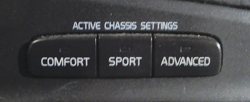
The controls for Volvo 4-C suspension are located on the dash of the vehicle.
This computerized system has a sophisticated microprocessor that computes the motion of the vehicle and adjusts the struts and shocks to ride smoothly. The Four-C system not only adjusts the struts and shocks, but also communicates with the ABS system. The sensors in the vehicle can receive braking information a few milliseconds before the brake pads touch the disc.
The Four-C system works with the ABS and the DSTC in a unique way, making the driver in full control of the ride they want.
The system consists of:
- Switch
- Acceleration sensors on the body, with two in the front
- Acceleration sensors in the suspension, one at each front wheel
- Damper solenoid one at each strut/shock, four total
- Position sensors, one at each rear wheel
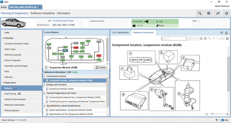
- Suspension Module (SUM)
- Acceleration sensor, one in the rear of vehicle.
The Volvo Four-C system is a highly advanced suspension system that makes driving safer and more pleasurable.
When the car is accelerating, Four-C receives the upcoming information from the longitudinal acceleration sensor. Similarly, the system passes on information about a sharp deflection of the steering wheel a few milliseconds before the car actually changes direction.
Replacing rear struts and springs on a 2007 Volvo S60
Lay down the back seats and open the trunk; remove the carpet to expose the top of the shock mount. Remove the bolt with washer on each side and raise the vehicle.
Remove the mud guard at the bottom of the control arms and the lateral link on both sides. Remove the two bolts on each side that secure the strut to the vehicle. Using a come-along or a retaining strap, connect to each control arm, and compress with slight pressure.
If vehicle is equipped with Four-C, be sure to disconnect the electrical connector and feed it out of the way.
Remove the bolts at the bottom of the struts that connect the shock to the control arm. Now you can wiggle the complete strut/spring assembly out of the vehicle. Before disassembling the spring strut, be sure to mark the rubber shim and spring seat.
Secure complete strut assembly in a vise or use a wall mounted spring compressor, and compress the spring. Use Volvo tool 9995500 to remove the nut at the top of the strut.
Remove the top mount and replace the rubber shim, if needed, when reassembling. Remove the strut from the spring and install the new strut through the spring, making sure to align the spring at the bottom of the spring seat. Install the top mount and align the marks that were made earlier. Install the top nut and tighten with tool 9995500.
Decompress the spring and install the strut/spring unit into the vehicle. The assembly will only go in one way. Install the two bolts that hold the assembly to the vehicle chassis and tighten. Install the bottom bolt at the control arm through the strut and secure.
Remove the tension strap from the control arms, and install the mud guard at the bottom of the control arm and lateral arm.
Lower the vehicle and install the bolt at the top of the strut assembly and tighten. Reinstall the carpet and set the seats back into place.
Test drive the vehicle to make sure all is well.


0 Comments