


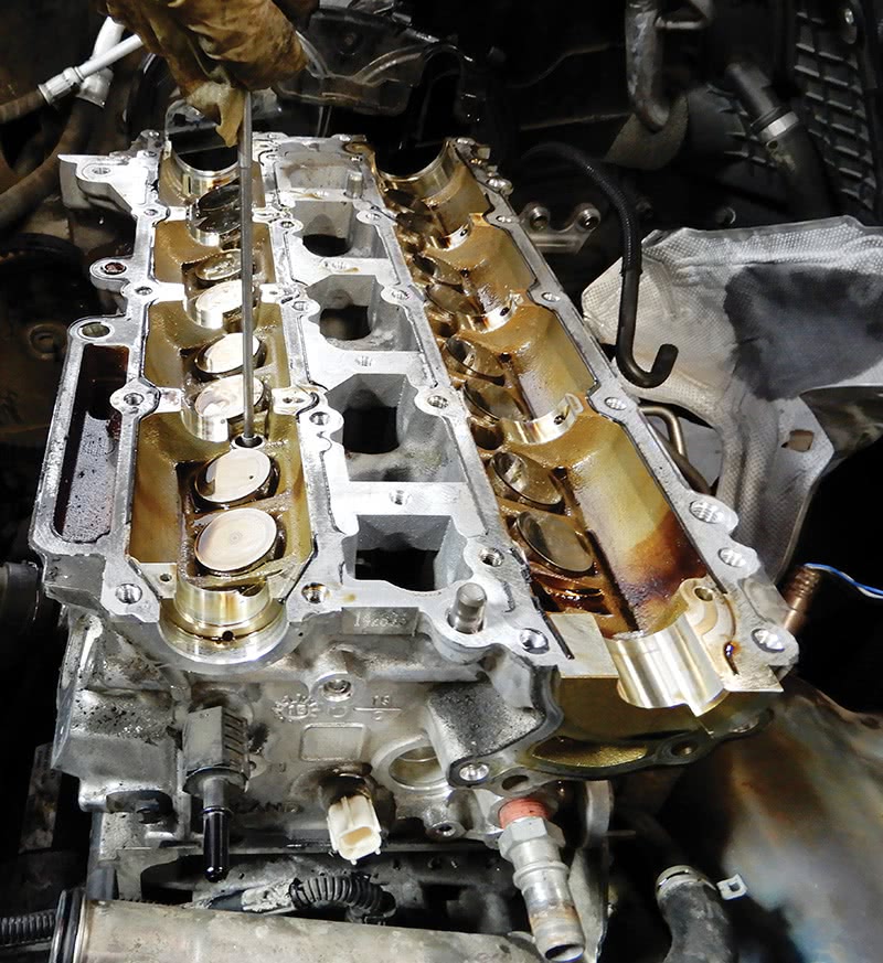
When a high mileage Volvo is due for overhaul, pay careful attention to the installation of new pistons and piston rings.
Have you ever had a customer come in and say, “I’ve been putting a lot of oil in my vehicle, but I don’t see any leaking on the ground,” only to find yes, the customer was right, there are no external leaks from the engine? The customer might also share that the Low Oil message keeps coming on. Technical Journal TJ 31216.5.0 can shed some light on this problem.
Well, the first thing to do is to find out whether the cylinder head valves have leakage past them or if the loss is farther down into the pistons and rings. This can be accomplished by doing a leakdown test.
To do a leakdown test, you will first need a leakdown tester tool setup. Remove the spark plug from the cylinder you are testing, and turn the engine over until it’s at top dead center. Then insert the tester tool into the spark plug hole and add air pressure to around 100 psi.
Five to ten percent loss indicates an engine in good running condition. An engine at ten to twenty percent loss can still be a good running engine. Anything above twenty percent indicates that the engine needs attention, possibly a rebuild. Anything above thirty percent indictes that there are definite problems. The percent of leakage should also be consistent across the cylinders. If there is a big difference, the low cylinder has a problem and will need attention.

With the tester connected, listen for escaping air pressure. You may have one of the following scenarios:
Intake Valve: Air whistling out of the intake or throttle body indicates a leak at the intake valve.
Exhaust Valve: Air pressure heard at the tailpipe, exhaust manifold, or turbo indicates the exhaust valve is leaking.
Piston Rings: Hissing out of the oil filler cap or dipstick tube means air is pushing past the piston rings.
Head Gasket or Cracked Head: Air bubbles in the engine coolant could mean air is escaping past the head gasket, or coolant rising in the expansion tank could mean a cracked cylinder head.
After checking each cylinder in the engine and finding air escaping from the oil dipstick and from the oil filler cap, we concluded that, on this Volvo, the piston rings were likely bad and overhaul would be necessary. If you find this condition on a similar Volvo, it’s probably time for an overhaul. Here is a suggested procedure.
Position the vehicle on a hoist, drain the oil and coolant from the engine. Disconnect the battery. Remove the rear lower mount and install special tool 9997534 and tool 9997533 to hold the engine in place. Remove the top right-side torque mount.
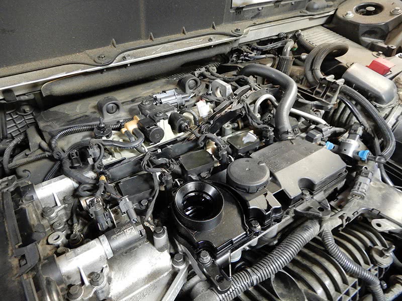
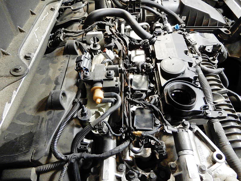
Remove the oil trap from the top of the valve cover. Disconnect the coil pack electrical connectors and to remove the coils. Disconnect and remove both intake and exhaust camshaft solenoids. Remove the ground leads on top of the valve cover. Disconnect the injector electrical connectors. Disconnect the vacuum hoses and electrical connectors at the decanter and vacuum regulator; remove the three bolts that hold to the valve cover and set aside.
Release the fuel pressure at the hard line to injector rail; catch any escaping fuel with a rag. Use Volvo tool 9814198 to remove the pipe. Remove the four bolts at the fuel rail and remove the fuel rail from the engine. If the injectors don’t come out with the rail, use tool number 9997815 to extract the injectors from the cylinder head.
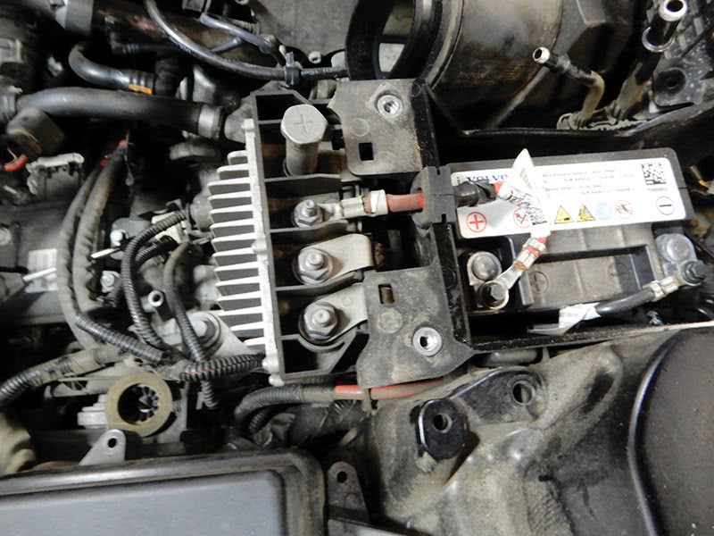
Remove the air filter box assembly and the hose to the supercharger. Remove the wiper arms and remove the cowling at the bottom of the windshield. Remove the top cover of the small battery. Disconnect the battery and remove. Disconnect the electrical connectors and remove the battery box from the vehicle with the battery control switch module.
After the windshield cowling is removed, remove the three bolts that hold the windshield wiper assembly in place and remove from the vehicle. Remove the aluminum crossbar from strut tower to strut tower.
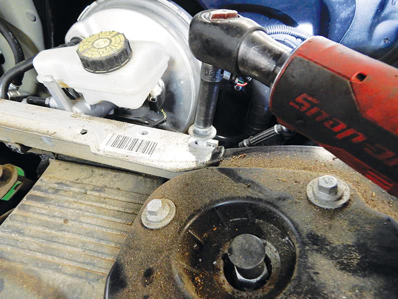
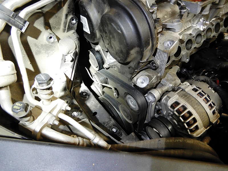
At the front of the engine on the right side of the vehicle, completely remove the engine mount and ground cable. Remove the auxiliary drive belt and pay attention to the routing of the auxiliary belt. Remove the idler pulley and bracket; two bolts hold it in place. Remove the covers around the timing belt.
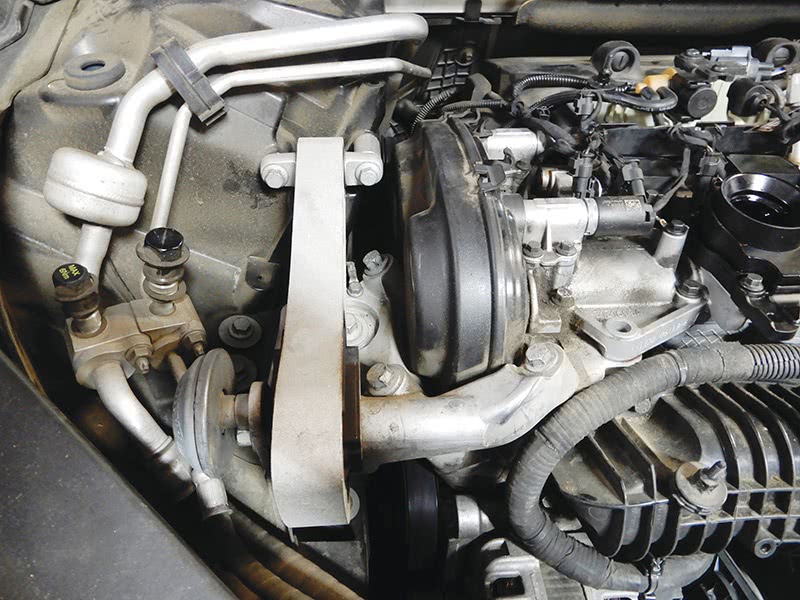
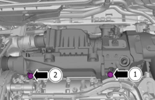
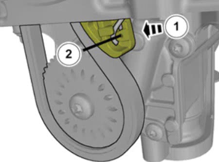
After the auxiliary belt and idler pulley are out of the way, you can now remove the two bolts at the supercharger just under the front pulley of the supercharger. After removing the top two bolts, bolt 1 has an adjuster in it that squeezes the supercharger against the head. Loosening this bolt will allow the supercharger to move. Disconnect the clips and the electrical connector that runs down to the turbo and pull up to remove it out of the way. Remove the cover around the supercharger. Remove the panel close to the firewall; two bolts secure it in place. Also, remove the plastic cover that surrounds the inlet for climate control, in the recirculation flap area.
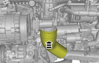
The plastic pipe from the supercharger to the turbo will need to be removed. Remove the bolt at the top bracket at the supercharger and pull the bracket straight up and set aside. Remove the right front tire. Remove the inner fender well so to access the plastic pipe to the turbo. Remove the bolt and remove the clip that holds the pipe to the turbo. Carefully remove the pipe from the vehicle.
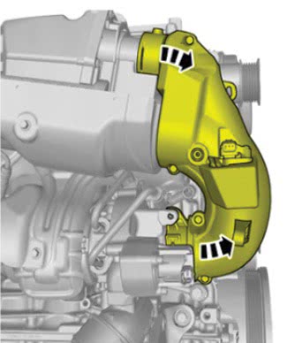
Remove all vacuum lines and disconnect the pipe that is connected to the supercharger near the air cleaner assembly on the bottom of the supercharger. Remove the bolt from the supercharger at the back of the cylinder head. Remove the two top bolts at the top of the supercharger.

Disconnect both oxygen sensor connectors and set the wires out of the way. Pull up on the supercharger and carefully remove it from the vehicle.
Remove the heat shield at the top of the exhaust manifold. Lift the vehicle completely up and remove the pipe and hoses from the turbo to the intercooler. Lower the vehicle and remove the seven bolts that hold the exhaust manifold to the cylinder head.
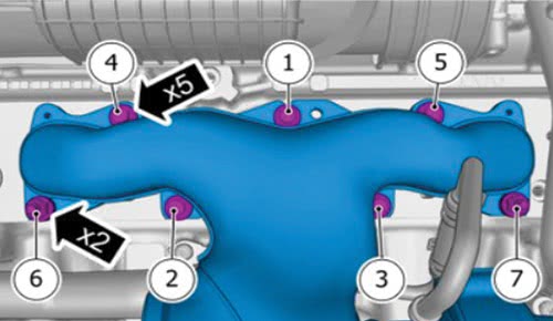
The intake manifold will need to be removed next. Disconnect the wire harness that runs across the top of the manifold, and disconnect the throttle housing connector. Remove the bolts that secure the harness to the engine. Disconnect the evap valve and hoses, and remove the bracket and valve. Disconnect the hose at the front of the intake manifold. Remove the hose at the bottom of the throttle housing.
Remove the six bolts that hold the manifold to the cylinder head, and remove the manifold from the vehicle.

Now that the manifold is out of the way, let’s remove the water pump. Disconnect the radiator hose from the water pump, then disconnect the electrical connector from the pump. Make sure there is no corrosion at the connector; if so, clean thoroughly before installing. Remove the three bolts that hold the pump to the block and remove the pump.
Disconnect the coolant hoses at the back of the cylinder head. Remove the two bolts at the injection pump and remove the pump. Remove the hose to the vacuum pump and the three bolts that hold it on to the head, and remove the vacuum pump.
Remove the plug at back of the head at the intake side, drill a hole in it and pop it out. Turn the engine until the camshafts are in alignment to install Volvo tool number 9997490. This will hold the camshafts in place when removing and installing the timing belt components.
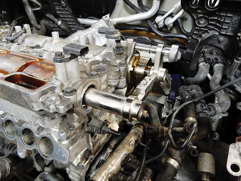
At the front of the engine, remove the idler pulleys and the tensioner for the auxiliary drive belt. Remove the two bolts that hold the plastic timing cover on and remove the cover. Now the timing belt is visible and can be removed. Remove the front vibration damper. Use tool number 9997495 to hold the damper in place so you can remove the center bolt. Remove the other four bolts and remove the vibration damper.
Check the alignment of the front crankshaft pulley; this should be in place after installing the tool at the camshafts. Install tool 9997497 and 9997497-1 to hold the camshaft sprockets in place. Turn the VVT units clockwise until they stop and tighten down the two nuts on both sides of the camshafts to lock them in place.
Remove the bolt from the tensioner and remove the tensioner and timing belt. Remove the tool at the front of the VVT pulleys. Now remove the center bolts at the VVT units and remove both VVT pulleys. Remove the 26 bolts that hold down the valve cover and remove the cover from the engine. Remove both camshafts from the engine. Make sure not to damage the camshafts. Remove the valve tappets, making sure to mark them and keep them in order, so to put them in the same place when reassembling.
Remove the cylinder head from the engine block. Make sure to have the cylinder head checked out and seals replaced before reinstalling.
Remove the crankshaft front pulley using tool number 9997493 and 9997493-1. Remove the four screws that hold the plastic cover to the engine and set the cover aside. Remove two bolts that hold the front seal in place and remove the front seal assembly.
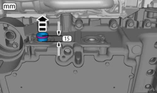
Now to remove the oil pan. Remove the turbo intercooler pipe at the bottom of the engine and hoses. Remove the oil cooler on the side of the oil pan and the oil filter. Looking at the oil cooler, pull out the inside oil pipe on the left about 15 mm.
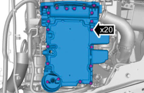
Remove the electrical connector for the oil sensor at the bottom of the oil pan. Remove the bolt that holds the sensor in and take out the oil sensor. Remove the 20 bolts from the oil pan and remove the pan from the engine.
Push the tensioner for the oil pump chain and remove the chain from the sprocket.
Remove the oil pickup assembly. Disconnect the electrical wire through the block and pull it out of the engine block. Remove the four bolts for the oil pump and lift out the oil pump from the engine.

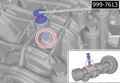
Remove the seven bolts that hold in the balance shaft assembly and remove it from the block. Install Volvo tool 9997613 at the balance shaft to keep it in alignment.
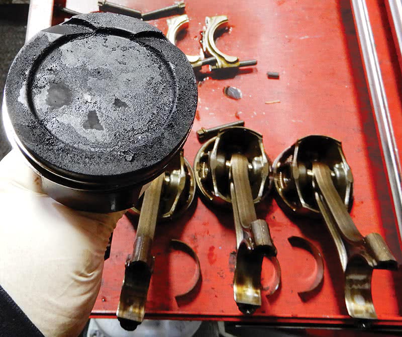
Remove the rod bearing caps and push out the pistons one at a time and mark the rod caps to their connecting rods, keeping them in order, so when installing new pistons and rings they will go into the same cylinder.
When all pistons are removed from the engine, make sure to measure inside the cylinder walls so they are in spec to put in new pistons and rings. Check the cylinder wall for scratches—use your fingernail and confirm by feeling the cylinder wall. If cylinder walls have bad scratches or do not measure within spec,
the engine will need to be replaced.
Clean the connecting rods and remove the old rod bearings. Measure piston ring end gaps on the compression rings. Install new pistons on the rods by removing the wrist pin clips and push out of the old piston. Install each new piston onto its rod and install the wrist pin and clips. Install the piston rings onto each piston using piston ring pliers.
Make sure the rings are installed in the correct order: A is the top ring, B in the middle, and C, the oil ring, on bottom. Use TJ VCC 492577-1 to understand position of rings. Be sure to install rings with the proper side upward, and stagger openings of rings so they do not align. Rotate each ring in its gap to assure that there are no nicks and no pinching that would keep the rings from properly seating and rotating.
Install new rod bearings on the rods and install the rod caps, with the oil bearing side toward the crankshaft. Oil the cylinder walls and piston rings and, using a piston ring compressor, compress the rings and install each piston into its cylinder. Tap the pistons down into the cylinder. Install the rod cap and torque down. Using new bolts, torque stage one to 15 Nm, stage two 25 Nm, and stage three 90 degrees. Do the other three pistons one at a time the same way.
Spin the engine over each time you install a piston. Once all pistons are in place and rod caps are torqued on, spin the engine just to make sure it feels good and easy.
Reassembly of All Engine Components
Starting with the balance shaft assembly, make sure to use new bolts when assembling. Set the balance shaft assembly in place and install two bolts, finger tight. Remove the Volvo special tool that was installed at the balance shaft assembly.
Install the remaining bolts into the balance shaft assembly. Adjust the assembly as necessary, and torque down the bolts to 8 Nm and then 210 degrees.
Install the oil pump and finger tighten the bolts, then torque to 17 Nm. Push the tensioner back and install the chain to the pump. Install the pickup assembly. Feed the electrical wire through the block and tighten the bolt.
Clean the oil pan completely, clean the surface and add sealant part number 1161771. Install the oil pan onto the engine, finger tighten a few bolts to hold it in place. Add the remaining bolts and torque down to 17 Nm.
Install the oil pipe at the oil cooler into the pan and push into place. Install the oil cooler and tighten down. Install a new oil filter, and tighten the oil plug for draining oil.
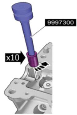
Install a new front crankshaft seal. Clean the top of the engine block and lay down the new head gasket. Install the cylinder head with exhaust studs and exhaust gasket, and slide the head into place. Install the thread sleeve in each head bolt hole and torque to 10 Nm using special tool number 9997300.
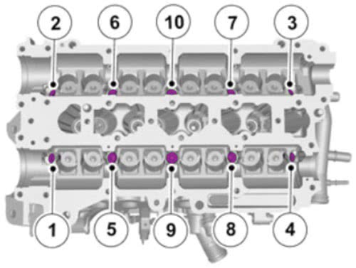
Install the head bolts and torque in the correct sequence:
- Stage one: 40 Nm
- Stage two: 120 degrees
- Stage three: 120 degrees
Oil the tappets and install them in their correct order, the same order they were taken out. Oil the camshaft journals and install the camshafts. Camshafts must be in a certain position.

With the camshafts in place, at the front of engine, make sure the oil holes for the sleeves are pointed upward. Make sure the clips at the front of the camshafts have their openings pointed upward also. Clean the valve cover completely and assure that the surface is free of any particles. Install chemical gasket 1161771 on to the cylinder head and install the valve cover. Torque down the 26 bolts at the valve cover in sequence to 17 Nm.
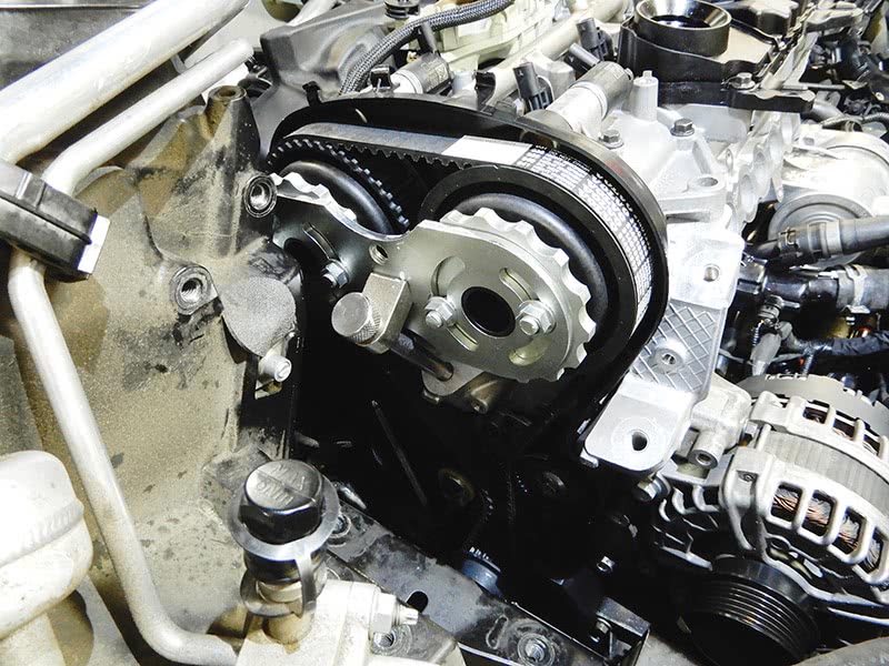
Now that the cylinder head and oil pan are complete, let’s install the timing belt, idler pulley, and tensioner. Install tool 9997490 at the back of the camshafts. Install the plastic inside cover at the front of the engine. Install the camshaft seals using tool number 9997496.
Install both front VVT pulleys at the camshafts, and install the center bolts and tighten finger tight for now. Install the special tool at the front of the camshaft pulleys and tighten the four nuts finger tight. Install the timing belt and adjust the tensioner to correct position and tighten to 24 Nm.
Tighten the four nuts at the tool for the VVT pulleys. Using special tools 9814244 and 9997673, tighten the center bolts to 90 Nm. Remove the special tool at the VVT pulleys and the tool at the back of the camshafts. Spin the engine over, turning clockwise a couple of times and make sure the alignment is good. Check the belt tensioner and make sure it’s in the correct position.

Tighten the bolts at the exhaust manifold to 20 Nm and install the heat shield. Install the vacuum pump at the back of the engine. On the bottom of the supercharger, screw in the mount.
Install the shield under the supercharger and set the supercharger in place. Install the two top bolts and finger tighten them for now. Install the two front bolts at the front of the supercharger and tighten to 24 Nm. With the two top bolts holding the supercharger in place, tighten the front one closest to the front of the engine to 50 Nm. Remove the one at the rear and insert special tool 9997508 and screw it down until it bottoms out. Remove the tool and install the bolt and torque to 17 Nm.
Install the plastic pipe from the supercharger to the turbo and secure. On top of the engine, install the vacuum decanter and vacuum regulator. Install the injector pump at the vacuum pump. Install the injectors and hard lines. Install the oil trap and spark plugs along with the ignition coils.
Connect all electrical connectors at the injectors and vacuum decanter, and connect the vacuum hoses. Connect the electrical connector at the turbo. Install the water pump using a new O-ring to fit into the water pipe.
Install the front cover over the timing belt area and front crankshaft pulley. Install the front auxiliary belt idler pulleys and tensioner and belt.
Install the intake manifold, and connect the hoses and electrical connectors. Connect the hose at the bottom of the throttle housing. Secure the fresh air pipe for the intercooler that runs at the bottom of the oil pan, and tighten the clamps for the rubber hoses.
Install the plastic cover at the firewall that protects the A/C system components. Set the wiper motor assembly in place and tighten the three bolts that hold it in place. Install the aluminum support bar from strut tower to strut tower.
Install the cowling over the top of the wiper assembly, and install the wiper arms. Install the engine mount at the front of the engine. Remove the special tool at the bottom of the engine at the torque mount, and install the mount.
Install the small battery box and battery control switch module. Connect all necessary electrical cables. Install the air filter housing.
Install the inner fender on the passenger side, and the front tire. Add oil and coolant to the engine. Start the vehicle and check completely, just to make sure everything is secure and working correctly. Test drive the vehicle and recheck fluids, topping off as necessary.


Question: I believe I will need my piston rings & pistons replaced based on a recent oil consumption test. I also have an air leak at my supercharger, and the gaskets are on order. I was quoted about $1200 for labor to replace the supercharger gaskets. Based on the information I am seeing on this post, in order for the mechanic to do the piston ring & piston repair, the supercharger would need to be pulled anyways, so there shouldn’t be any additional labor to only replace the supercharger gaskets. Would you agree with this?
It is recommended that while you have the supercharger out of the vehicle to leak test it since it can be common for high mileage vehicles to have a supercharger leak. On a side note the resealing instructions have changed for the cam/valve cover to cylinder head mating surface. Install RTV sealant to the cam cover instead of the cylinder head and always refer to VIDA for the latest information and best practice.
Kind Regards, Brandon
Should you not deglaze, plateau finish, or ball hone the cylinders to seat the new rings?
I put rags over the crankshaft to prevent contamination and material going into oil galleries in crankshaft.
IF NEW RINGS DO NOT PROPERLY SEAT IN, WILL HAVE A REPEAT OIL CONSUMPTION, AND/OR LOW COMPRESSION, AND POSSIBLE EXTREME OVERHEAT.
Hi Grant,
Our contributor shared some feedback on your question: