The concept of this terrific series from our Executive Technical Editor has evolved and grown from its original, less detailed, idea, which is a good thing. Here, Greg helps us really understand the idle, transfer, main, power, and accelerator pump circuits.
A carburetor works because of differential pressures. In fact, the entire car works on differential pressure! The pressure of the fuel pump moves fuel into the bowl; the pressure of a spring closes a choke plate and air flow past the offset of the plate forces it open as air flow acts on larger and smaller areas producing a rotational “pressure” to open the choke. The lowered pressure inside the engine is used to actuate a choke pull-off. The low pressure created by piston pumping induces atmospheric pressure to force flow through the carb, and as air flows past the main and boost vent is that flow increases in speed as it decreases in pressure and creates a low-pressure signal causing atmospheric pressure to move fuel from the bowl into the main well, and from there into the engine air stream where it’s drawn into the cylinders. Pressures can act in our favor or against it. For example, when they pulse or oppose the flows we’re trying to increase or improve.
The Wet Side
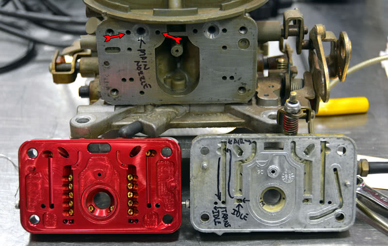
The “big three” of fuel delivery are the idle, main, and transfer circuits, which are all fed from the main well. This well, in turn, is supplied by two incoming sources — the main jet and the power valve restrictor channels. The well then feeds two out-flow points, the main nozzle directly from the main well and the idle/transfer circuit through a cross-drilled channel that route fuel into an idle and transfer circuit well.
Once running, fuel demand on the main well causes its level to rise and fall slightly depending on total jet area feeding the well, RPM, circuit activation, and air flow. This changing level provides a calibration point that is the result of and dependent on a properly-sized fuel pump and needle and seat, and a correctly-adjusted float system. This is a system — the pump pressure should be regulated if it rises over about 7-8 psi (your carb builder can tell you his or her preferred specification for pressure, and under what conditions that pressure should be measured). The needle size should be .110 inch up to about an 800 CFM carb, and .120 inch for a larger carb, and the float levels must be correctly set in order to calibrate fuel delivery. The whole fuel curve is set from bowl level.
A note about fuel pressure regulators: I’m not a fan if you can avoid them, particularly on street-driven, mechanical pump-equipped, pump gas cars. Pump gas volatility is all over the map these days and the typical non-return fuel pressure regulator is a great foam generator with its bouncing diaphragm and sharp edges. For race cars using an electric pump, a high-quality return-type pressure regulator is the only way to go since an electric pump has steady pressure and any foaming is confined to the return line back to the tank where it can settle down again. Watch your plumbing. Keep the return line at the other end of the tank from your suction line to avoid introducing vapor back into the suction of the pump.

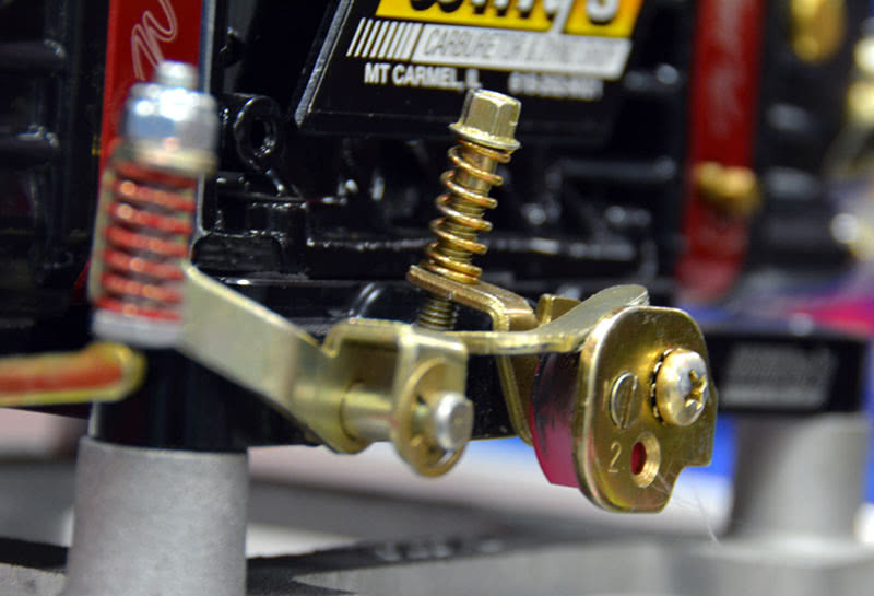
Holley makes several pump cams and each is color-coded and has two or three possible mounting positions. The number-one hole is typically earlier, and the number two and three holes are later. That’s not all: in many cases, the later holes may increase total pump stroke and volume. Make sure to recheck duration spring adjustment if you move the cam from one position to another. All you really want to do is keep the pump from being over-extended and bottom out because stretching the pump will cause it to fail early.
The main well level is designed to “auto-adjust” the spill height, which is the difference between the fuel level in the well and distance to the main nozzle feed port into the main body. As air flow increases with RPM, the flow through a fixed orifice isn’t always linear with increased demand and increased pressure differential, and the carb signal or vacuum signal generated by the boost and main venturi is not linear at all. In fact, the boost signal curves upward with increased carb flow, with the signal difference gaining strength on the order of four times for a doubling of air flow through the barrel. This is why air bleeds, jet sizing, and the design of the emulsion system are so critical — they trim off the tendency of the carb to go rich at high RPM by dropping the main well level below successive emulsion side air feed holes, introducing more air into the mix which “bends” the increasingly rich fuel curve downward. The upper holes on the emulsion side trim low-speed operation and the lower holes trim high-speed mixture. A well-designed emulsion system and properly-sized air bleeds can produce an air/fuel mixture that is nearly perfect, particularly if you have access to a carb builder who wet flows his work and knows how to select the best booster design for your application.
As I’ve said before, there’s just no reason not to use the services of a carb professional these days. In many cases, the prices are nearly the same as an out-of-the-box carb and you get a wet-flowed custom-built carb designed to work for your application. The amount of time you spend testing and tuning will be cut down to minutes instead of hours. If you’re buying all-out, custom-engineered, very high-flow racing carbs, the prices can get up into the $1,500-$3,500 range, and from the very few I’ve had access to they’re real works of art and worth every penny if your application demands that kind of flow rate (I must have it bad — they’re so pretty I just like looking at them).
Can you cut and try your way to success? Sure. Is that a worthwhile use of time, your most limited resource? Probably not. Do you need to track-tune all the time for air quality? Depends on the class you run and engine displacement. If you’re running a class that’s down to the thousandth, you’ll be tuning more than if you’re running any of the stopped ET classes like Super Comp, Super Gas, or Super Street. If you’ve got a lot of displacement, you may not see a great deal of improvement by jetting for conditions as large engines seem to be more forgiving of air/fuel ratios that are less than perfect. This all assumes that you’re running on a budget and lack full data-gathering packages — the pros all use high-end Race Paks to gather every bit of data they can from the car, which can add another $2,000-$10,000 (or more!) to a build, plus when you first install a data recorder you end up saturated in data that then has to be interpreted and applied correctly. More confusion!
Power Circuit
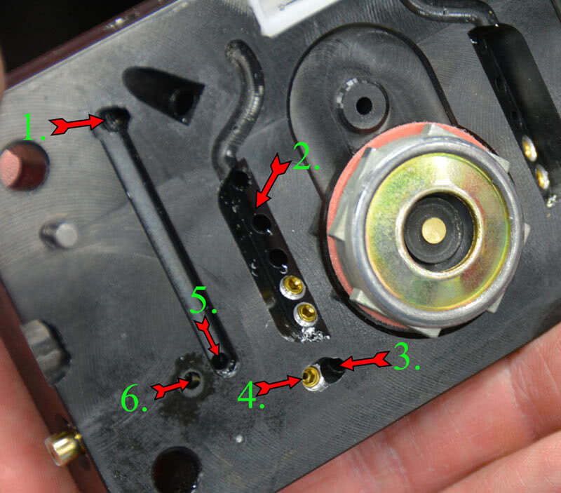
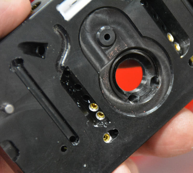
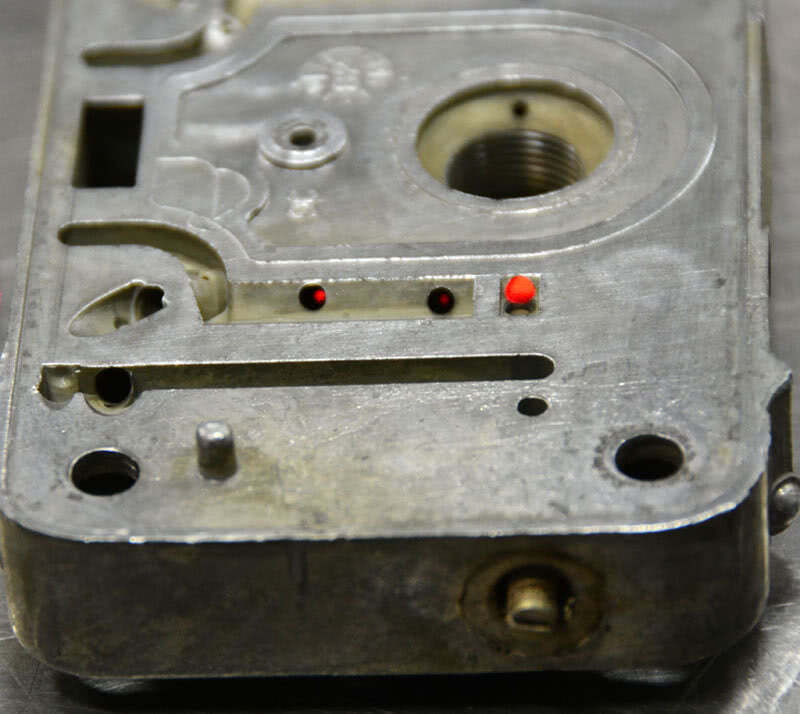
On aftermarket metering blocks, the power valve restrictors are replaceable and you can adjust the total area of the jetting (total main jet plus total power valve restrictor area) for best performance under load. The power valve restrictors on Holley stock metering blocks are pre-drilled, so if you want more fuel you’ll need to break out the wire drills and carefully and incrementally increase the restrictor diameter. If it comes to that, there are some very affordable billet metering blocks out there with replaceable emulsion and power valve restrictors that you might want to buy instead. If I were doing it, I’d toss the stock units in a drawer somewhere and buy billet.
You can tune with main jetting only, but that only changes the no-load air/fuel ratio. Main jets don’t affect all circuits equally since they control the level in the main well, which changes the spill height on the main nozzles while having little or no impact on the idle and transfer circuits. This is because they pull their fuel from the bottom of the main well and have their own restrictors between the main well and the delivery channel. If you can tune the power valve restrictors, then you’ll only affect the mixture under power conditions and that will have less impact on part-throttle mixture and fuel economy. You may also have to tune the power valve vacuum setting for your application.
The power valve should be selected so that the opening set point is about 2 in. Hg above the idle vacuum reading, taken in gear on an automatic. If your high-overlap, long-duration cam reads 7 in. Hg of vacuum at idle in gear, then a 4.5 in. power valve should do the job for you. Keep in mind that if your carb is sized too small, a very low-vacuum-rated power valve can be a problem at high RPM. If the carb is undersized, engine vacuum can build up again and shut down the power circuit as intake manifold vacuum builds back up with RPM. It’s not uncommon to use a large throttle plate with a smaller venturi main body to get good throttle response and drivability, so keep an eye on that and run a vacuum gauge on the car if you think it might be an issue. For racing applications, it’s sometimes necessary to plug off either the secondary power valve or the primary and secondary if need be and increase main jet size as much as needed to replace the fuel lost from the power valve restrictor. Replacing the power valve with a plug eliminates high RPM lean off when you’re running a small carb on a large-displacement high-RPM engine. The only downside is that the engine tends to be a little rich and blubbery at low- to mid-range operating speeds, and it’s a little easier to foul spark plugs.
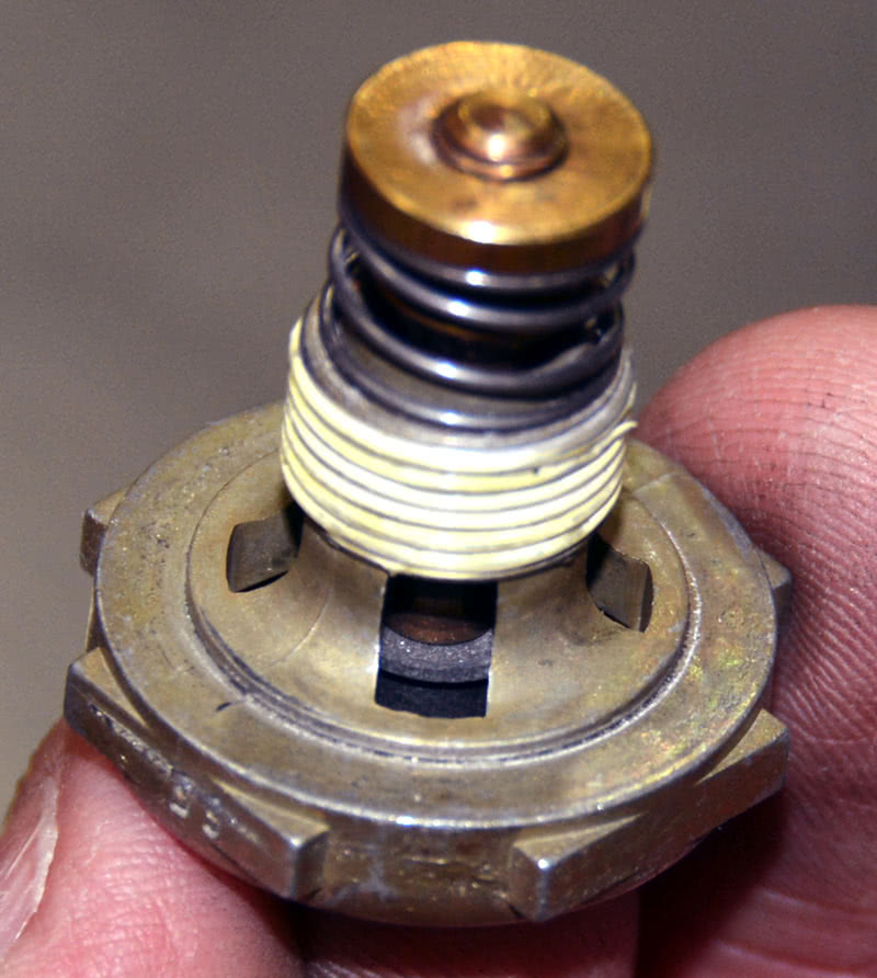
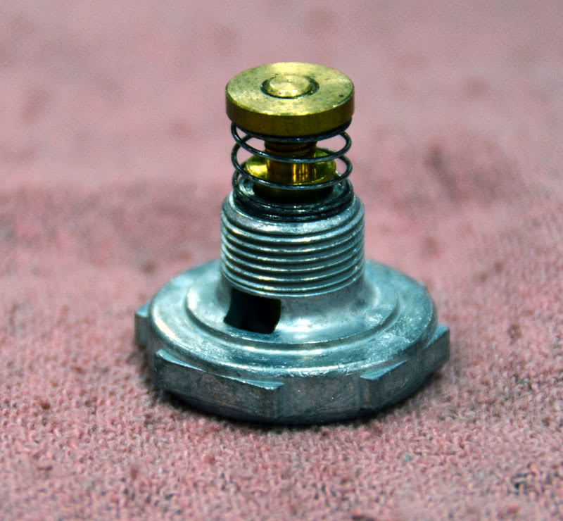
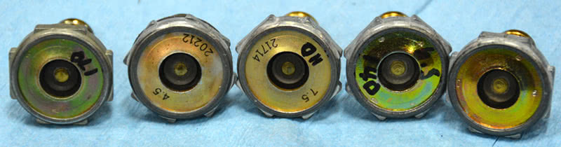
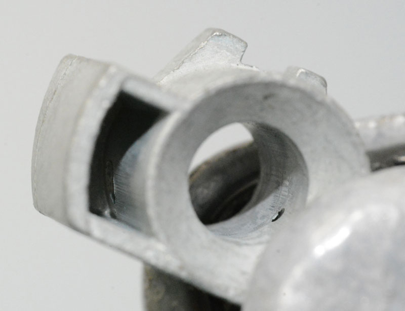
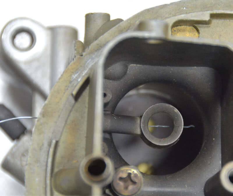
Holley power valves are stamped or inked with their opening set points, indicated in inches of vacuum Hg. They vary between 2.5 in. and 10.5 in. in one-inch increments and also are available as single-stage and two-stage, with two opening pressures on a single power valve to better trim the part-load mixture. The power valve installs into the metering block with a gasket or O-ring and seats into a deep chamfer so that fuel can flow into the channel the chamfer creates for 360 degrees so that the restrictors always see fuel.
If you intend to change jets or power valve restrictors, your best result will be if you record all dimensions before you actually modify anything, and calculate the total area for all feeds into the well. If you take fuel out of the jet to lean off part throttle cruise, you can recover the needed fuel for full throttle enrichment by increasing the size of the power valve restrictor. The key is to know the total area of all jets and make any changes to that area in percent so you can roughly calculate what your changes will do. That said, knowing and recording the total area is just a baseline because jetting is more than just about area.
The Vagaries of Jets
A word here about Holley jets. The number doesn’t necessarily correlate to the jet size, and getting your mixture trimmed may take more than one try. Up to about a #70 jet, the number and the size of the hole in the jet are roughly the same, but above that they vary. Jet sizes are made to yield about a 4.5-5.0% change in fuel flow per jet size, but they are far from precise. It’s more accurate to state that jets increase by 3.5% with a plus or minus factor of about 1.5%, so it could be as little as 1% richer or it may be near 5% richer — it just depends on manufacturing that day — which explains why changing jetting is sometimes a little frustrating. If the jet you remove is on the rich end and the next size up you install is on the lean end, you may only see about one percent increase in fuel flow. There are close-limit jets available in sizes from 60 to 74, and these are indicated by a -1, -2, or -3 on the end of the jet number, meaning lean, mid-point, and rich end of the flow window for that jet number, which can help you tune in a bit better. You can check for main lean-off unloaded by running the engine up to 2,500-3,000 RPM and monitoring mixture, but to see what loaded operation is, you’ll have to either drive it with wide bands in the pipes, or lash it down in a test cell with a gas analyzer.
Also know that the size of the orifice is only part of what determines the flow rate of the jet. The approach in and out of the bore and the bore finish are also part of the flow equation, which is why you should never drill jets, contrary to what the hot rodders of old commonly did. Buy what you need because drilling main jets doesn’t yield a consistent result.
Starting Point
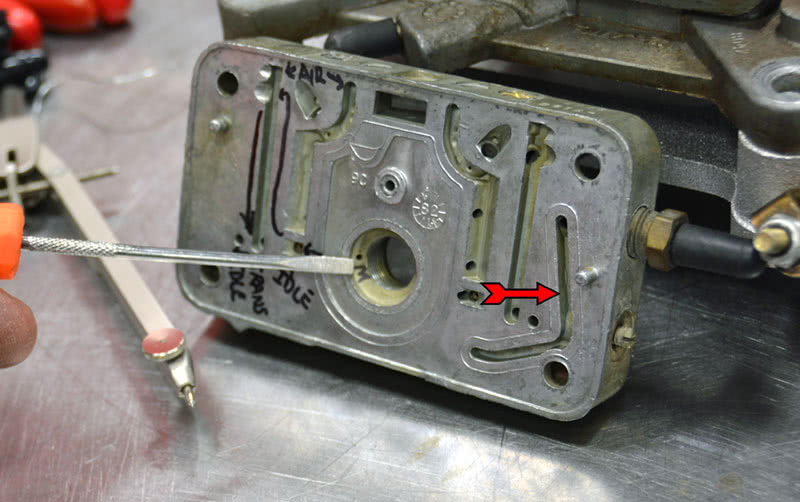
In my opinion, it’s a good practice after you get your carb from your builder to tear it down, look it over, clean it all out, measure and record the transfer, idle, power valve restrictors, and jet sizes, along with the emulsion hole patterns and sizes. Baselining it means you can always refer back to the as-built data if you do any changes that later don’t work out for you. I can’t speak for all builders, but the carb man I use (Patrick James at Pro Systems) delivers his carbs with a spec sheet and a rich-lean jet window that I can reference. I’ve bought several of his carbs and I’ve never been disappointed with the cost, quality, or results he’s given me.
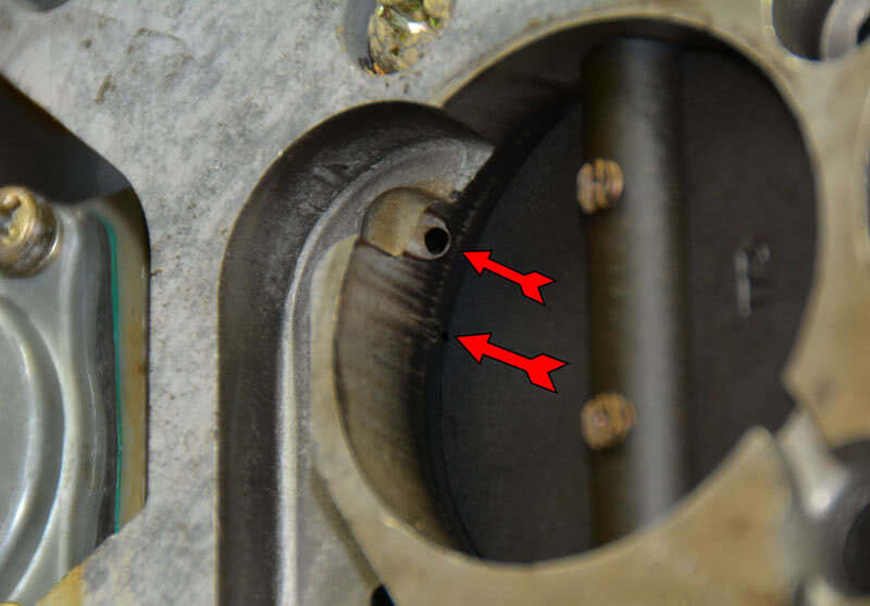
I usually start out with the carb “squared” with all four throttles opened just enough to expose a square area of the transfer slot. In other words, the throttle blade exposes an amount of the slot equal to the slot’s width. Is this an absolute rule? Not necessarily. I do it because it gives me a uniform starting point and on a four-corner idle carb I can’t see what it hurts. I’m a simple guy — I like simple and repeatable processes. If I have to adjust RPM, I then adjust the primary and the secondary throttle screws equally. Ditto for idle mixture, I set them all the same and move them all the same amount so that they’re equal. I count my turns on everything and write it all down so I can track changes, or bench-set it if I have to have it apart for any reason.
Remember that the transfer and idle circuits share the same fuel or wet side restrictor unless you’re dealing with a three-circuit carb, like some Dominators. If your camshaft requires opening the throttles too far to get a stable idle, you may find that you’ll start shutting off the idle discharge flow below the throttle plate and render the idle mixture screws useless. The only reason to avoid excessive throttle opening is because the idle circuit and transfer circuit flow shifts between the lower discharge hole (idle) and the transfer slot depending on how much of the transfer slot is exposed to engine vacuum. Or, you may have to close the throttles down because you start to pull the main circuits in early, which can cause dripping from the boosters. As the throttles open, the flow through the transfer slot “steals” all the fuel previously delivered to, and controlled by, the idle mixture channel and the adjustment screw.
From there, I adjust the primary and secondary throttle plates equally to get the required idle speed. If you really have to jack the throttles open to get your idle speed right, you’ll need to drill the throttle plates to allow enough of an air leak to close the throttles back down. You can always tell if you have to open the throttles too far when the idle mixture screws stop being effective as you wind them in and out, which tells you that you’ve got flow from the transfer circuit robbing the idle circuit. Normally, the idle mixture screws will be between 1-½ and 2 turns out for best idle, once the fuel restrictors and air bleeds are right sized and the carb throttle plates are evenly adjusted.
Too Much is Just Right
Can a carb be too big? Well, yes — and maybe. For the most part, it’s hard to make a carb too big today given how many options there are for throttle bodies, main bodies, and booster designs unless you go full-on stupid with it. The “old school” answer is, “Yes, too big and you’ll lose response because the venturi signal is too weak to pull fuel.” It makes some sense — if the venturi is large and the displacement is small, then the air pump isn’t big enough to cause adequate flow to pull a sufficient vacuum signal on the main nozzles to get flow early enough to make a smooth transition onto the mains. Given the design options that builders have today with booster nozzles, however, an outstanding carb man can custom build you a carb that is “too big” and still tire-shredding responsive. The good part is that bigger really is better for making top-end power, so if your carb guy can control the transitions and all-out top-end power is the name of your game, then make it big. Now, of course if you take it to the absolute extreme you can certainly make it too big, but you may be surprised at how big you can make it before it becomes undrivable.
Accelerator Pump Circuit
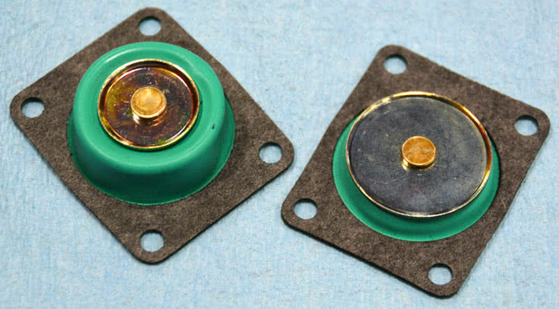
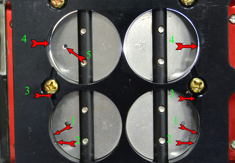
The accelerator pump is a simple circuit designed to overcome the difference in how fast air starts moving versus how fast fuel starts to move. Because fuel has more mass, it lags behind air and when the fuel lags the mixture leans out. The pump cup delivers fuel to the nozzle; the size of the nozzle determines the how much fuel is delivered (rate) and how long the shot of fuel lasts (duration). The duration is an accident of nozzle size — a larger nozzle dumps more fuel more quickly, so larger nozzle sizes increase rate, but decrease duration. If the 30 cc pump is too small to deliver the amount and duration in correct proportion, then a 50 cc pump kit is available for both primaries and secondaries. Those ratings are for 10 pump strokes, by the way, so it’s 3 cc per stroke for the 30 cc pump and 5 cc for the 50 cc pump kit.
There are several tuning items in the accelerator circuit. Determining what you need to tweak or change in the pump circuit is accomplished with a test drive. Hesitations or backfires with rapid throttle movement indicate a lean condition and require one of several fixes. First of all, pump nozzles come in a number of sizes and in three configurations — tube, drilled, and anti-siphon. If you’re lean, the first thing to do is change the pump nozzle, and each step should be an increase of .002-.003 in. If you find yourself with a nozzle size over about .040 in., you’ll need to verify that you’re using a hollow nozzle hold-down screw so that you’re getting all the flow you should. If you get north of .037-.038 in., you might want to look at going to a 50 cc pump kit. The Holley accelerator pump also has a wide assortment of pump cams available, all with different delivery rates and delivery timing. Pump cams have at least two mounting holes in them. The #1 hole is typically used for cars idling at or under 950 RPM, while the #2 hole works well for cars with a higher idle. #1 hole tends to be earlier and less total lift, and #2 hole tends to be later with more total lift, but you have to check because that’s not always true for all pump cams. They’re easy to replace, so changing them and experimenting isn’t too time-consuming.
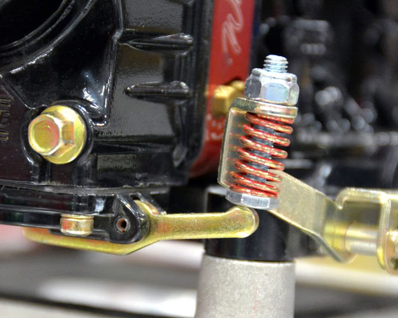
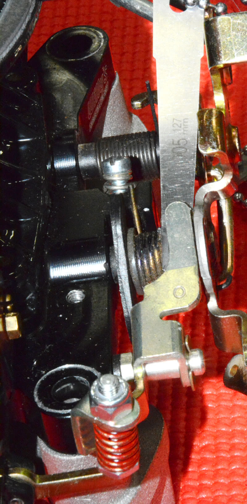
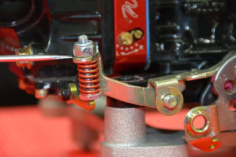
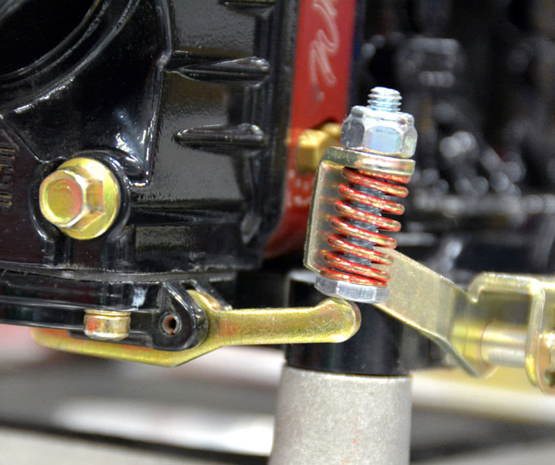
Once you’ve landed on the nozzle, screw, and pump size and cam, the last thing to do is correctly adjust the duration spring by holding the throttle wide open and adjusting the clearance between the pump arm and the cam to .005-.015 in. to avoid forcing the pump cup past its limits and damaging it. Just make sure that the adjusting nut on the duration spring is seated against the pump arm (no daylight under it) before you adjust the arm to cam clearance. The duration spring overrides the pump arm and follows the pump lever down, increasing the length of time the pump shot is delivered.
The Answers Are Out There
I hope this quick primer will get you started out on the right foot. There are several good books written by some outstanding authors on the Holley series of carburetors and I’d suggest you buy several and read them all if you’re looking for a more complete understanding of carb theory, operation, and tuning. Each author has his own approach, so there’s something to be learned from each of them and they’re all worth reading.