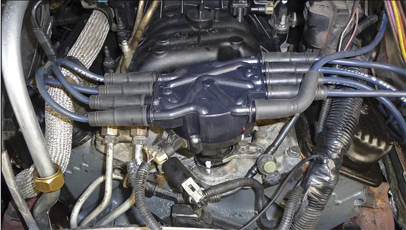
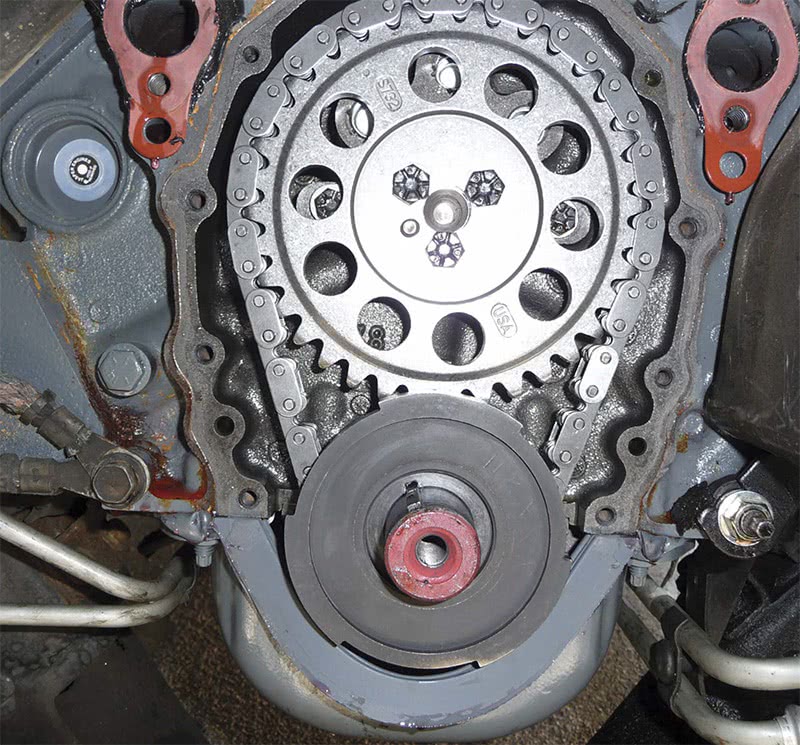
I was called to a shop for a complaint on a 1997 Chevy van with a 5.0L engine (Figure 1) with a hard start no start problem. The shop had just replaced the engine because the old engine had a lower knock in it caused by a worn bearing. The old engine did run and the customer drove the van to the shop with no problem other then the knock in the engine. This is a situation that many of us have been in before working in the automotive field at one time or another. It’s a bad feeling to drive a vehicle into the shop and later having to push it out. The blame solely lies on the shop even if it isn’t the fault of the shop because a jury conviction will sway to the customer’s side in court in this case.

The mechanic who put this engine in was well experienced in small block and big block Chevys. He actually restored a 1969 Chevy Chevelle with a 396 to senior show level specifications and even went as far as to make sure the replacement water pump fell within the correct serial number runs to pass show criteria. So you can only imagine how this mechanic felt after installing this engine in a flawless installation and now ending up with a no start. He did discover that if he pulled the cam sensor connector the engine would start up but run poorly. This prompted him to replace the cam sensor but the problem still remained. He even tried a crank sensor just in case it was damaged during the install procedure. It seemed as if the timing was off so he even checked the orientation of the distributor 3 times. He was very tempted to replace the Engine Control Module but at this point the shop decided to call me in for a second opinion.
When I arrived at the shop I attempted to start the engine but the engine labored to start and would not catch. I removed the cam sensor connector as per the mechanic’s suggestion and the vehicle started up but ran very poorly. The engine did not rev up well and had no power in drive while I power braked the engine. It was at this point I decided to grab my pressure transducer and place it within the cylinder so I could determine if the engine rebuilder had indeed properly lined up the timing chain. I placed one of my scope leads on the pressure transducer to check valve timing and another scope lead on the inductive clamp placed around the plug wire for the same cylinder with a spark tester to check spark timing. I cranked the engine and captured a waveform (Figure 2). Each large purple cursor represents 180 degrees of crankshaft rotation while each small purple cursor represents 30 degrees. The large pressure peak represents TDC compression and the first large purple cursor after the large pressure peak represents BDC of the power stroke. After the peak rise the waveform should drop drastically and starts to rise about 30-45 degrees before BDC of the power stroke. This is the point when the exhaust valve will begin to open. By viewing this waveform it was determined that the valve timing was correct.
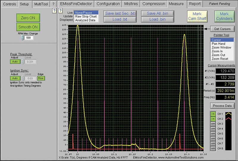
If you look at the red synch waveform representing spark timing you can see that the spark was occurring about 30 degrees before TDC compression while cranking the engine. The only way this could happen is if the crank and cam sensors were out of correlation.
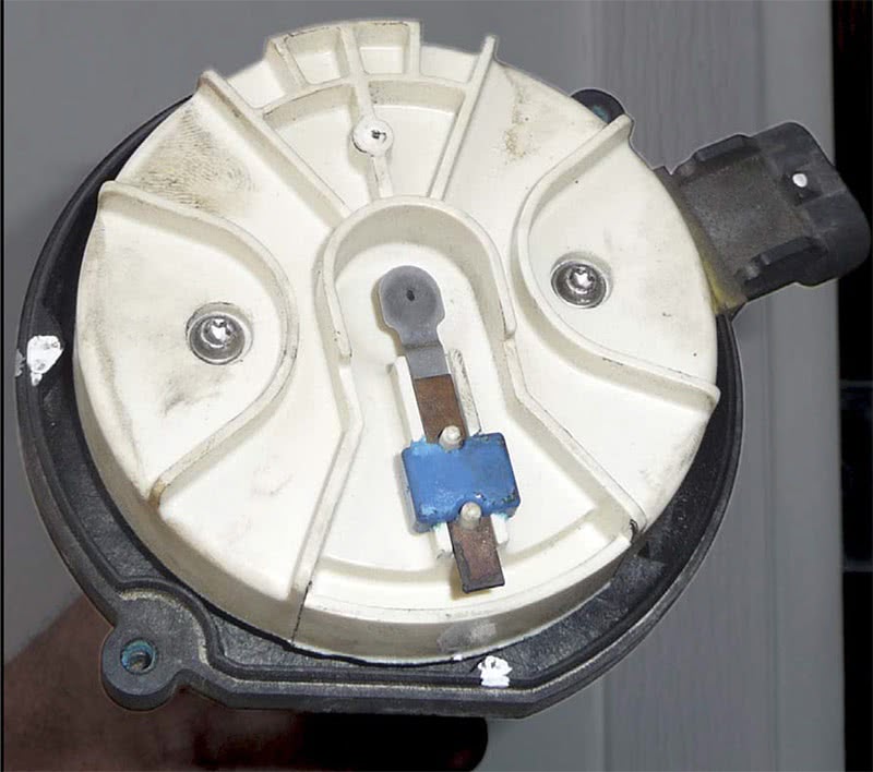
At this point I turned to the mechanic and questioned his ability to set the distributor in properly. He gave me a look like “Are you kidding me dude?”. But I had to ask anyway because the waveforms don’t lie. The mechanic proceeded to show me how he was careful to mark the distributor housing base with the intake manifold to guarantee a correct orientation of the distributor housing location (Figure 3). He next schooled me about the same distributor being used for both the 4.3L and 5.0L and how there were two different positions to index the rotor to the distributor housing (Figure 4). The 6:00 position as viewed in Figure 4 was labeled with a number 8 for correct orientation. It was then only a matter of dropping the distributor into place on TDC compression for #1 cylinder which he did three times.
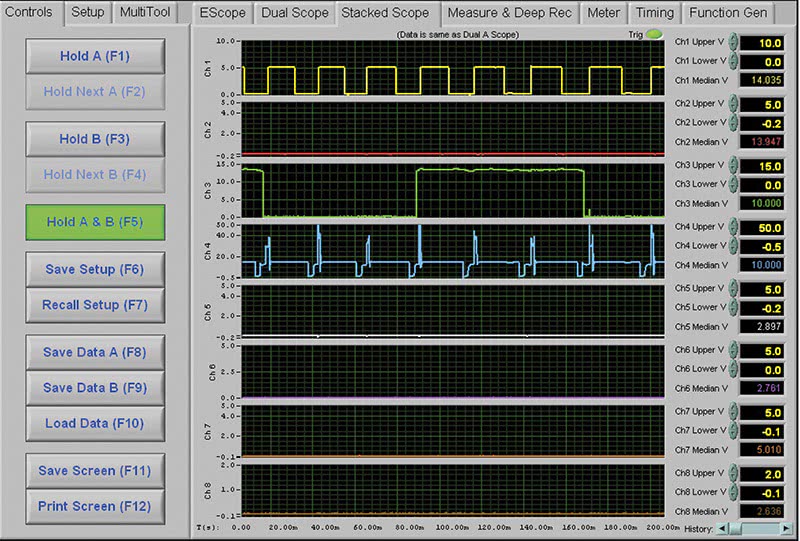
To prove things further I decided to scope check the crank sensor, cam sensor and the. coil primary to see if the signals were in synch and to make sure we had 8 good coil firings without dropouts. While cranking the engine I captured a waveform (Figure 5) to compare to a good known waveform from Thompson Automotive Labs (Figure 6). As I looked closer at both waveform files I noticed that the one captured from the vehicle showed only 6 coil firings with one revolution of the distributor and looking at the crank signal I only saw 6 square waves. This engine had to have a wrong crank trigger wheel in it.
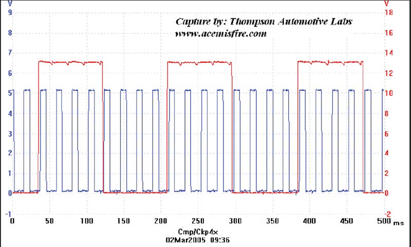
To prove my findings I waited at the shop while I had the mechanic remove the front crank pulley and timing cover. When the timing gears were revealed, to our surprise we found our culprit (Figure 7). The engine rebuilder had accidentally installed a trigger wheel onto the crankshaft for a 6 cylinder engine instead of one for an 8 cylinder. What a nightmare unveiled! I kind of felt sorry for the shop for all the time they had into dealing with this dilemma. You can’t always trust parts you buy and now it’s a point where you can’t even trust a rebuilder to do his job.
I went back the next day to capture a picture of the correct trigger wheel. You can see by laying both trigger wheels side by side that they are both configured to fit on the same crankshaft with no problem at all (Figure 8). The only difference here was that the correct one had 4 triggers per revolution. The mystery was now solved but this was some battle for the shop who could not be paid for all their lost time and unwanted parts. The rebuilder did however apologize and said plainly “It Happens!” I just hope that this one will help to teach you to never take anything for granted and always go with your first feel when you encounter a problem vehicle.

by John Anello


I’m curious what John was monitoring in figure #2, as far as the purple 180 and 30 degree signals (perhaps CMP and CKP). Shouldn’t the 30 degree signal been a clue? Should they instead be at 22.5 degrees for a V-8?
Nice article, well written.
I’m curious what John was monitoring in figure #2, as far as the purple 180 and 30 degree signals (perhaps CMP and CKP). Shouldn’t the 30 degree signal been a clue? Should they instead be at 22.5 degrees for a V-8?
Nice article, well written.