

I was called to a shop on a 2004 Chevy Corvette with a no-start condition (Figure 1). There was no communication with the PCM and the security light was on. This prevented the engine from cranking. The tech had already checked all PCM powers and grounds, but was reluctant to condemn the engine control module because of the costs involved if he was wrong. There was a good chance that this would turn out to be a costly marriage, and there’d be no turning back. Divorcing an un-needed part is always a bad scene. So, at this point the garage opted to call me in for a second opinion.

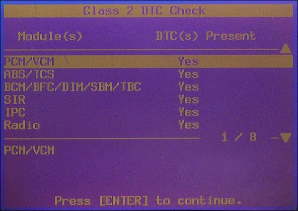
When I arrived at the shop, I hooked up my GM Tech 2 factory scan tool to verify the complaint. I could not get any communication with the PCM. This could be due to a loss of power or ground, an open or shorted data line, or possibly a bad PCM. I chose to test the entire network to see whether or not this was an isolated communication fault or a network problem. This vehicle uses a one-wire communication system, and if the PCM was off the network there would be “U” codes stored in other controllers. A controller that sets a “U” code is basically pointing a finger out into the network and saying “How ‘U’ Doin!” so as to draw attention away from itself. A “U” code does not mean the problem lies within the controller you are scanning. The Tech 2 supports network checking that most aftermarket scanners don’t. It’s a very important feature that can reduce the diagnostic time on a vehicle. It’s like doing a role call that pings all modules on board to see who responds and who is alive on the network. Simply navigating to the Class 2 DTC Check feature (Figure 2) allows the scan tool to interrogate each controller for a health check and code status. When I initiated this function, I received the message “No Communication with Vehicle” (Figure 3). This Corvette did not just have a PCM communication failure but also a network issue causing all controllers to be unresponsive. This is why it so important to use your scan tool to interrogate all possible modules that it supports because you just don’t know how wide your problem is.


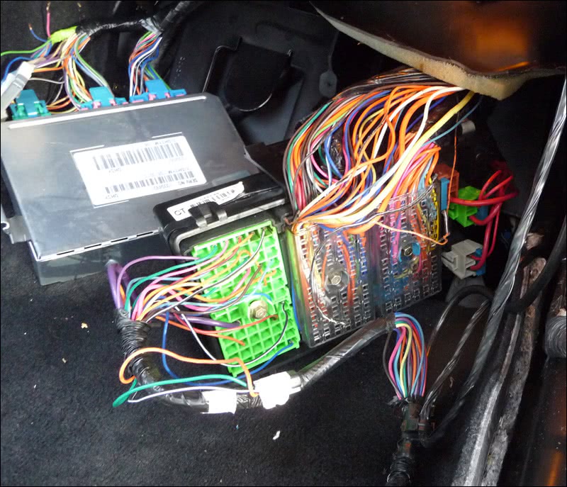
Some manufactures will place network lines into one accessible area for simplified testing, while others may fragment different groups of network connectors throughout the vehicle. This Corvette had two star network connectors conveniently located under the right side dash next to the PCM (Figure 4). I was lucky that day to have in my possession the Kent Moore Tool #J42236-A. I purchased it a while before to hook into both of the network connectors. This isolates the PCM from all the controllers on board and directly links it to the data link connector to program the PCM in isolation mode. This prevents any controller network noise from affecting PCM programming. This tool has the ability to isolate each controller to the data link connector one at a time by the use of two selection knobs, allowing me to go into each controller seperately to see which one had an issue.
I removed the star connector combs from the star connectors and installed the Kent Moore tool (Figure 5). I printed out a computer data line diagram from Mitchell-On-Demand and started checking off controllers that did respond as I moved the tool selector knobs (Figure 6). All responded except for the Electronic Suspension Controller module, Remote Control Door Lock module, and the Driver Seat Control module. The fact that all the other controllers worked independently proved to me that one of these three unresponsive units was at fault. It was like rolling the dice at this point — I had to decide which one of these three was the culprit. I removed the tool and placed the star connector combs back in place. I cut the wire to the ESC module and I still had no communication with the scan tool. I next cut the RCDL line (Figure 7), and, lo and behold, I got communication back with all the modules on board (Figure 8). The security light went out, so next I cranked the car and the engine started. Okay, I got the car running, but what about the RCDL issue?

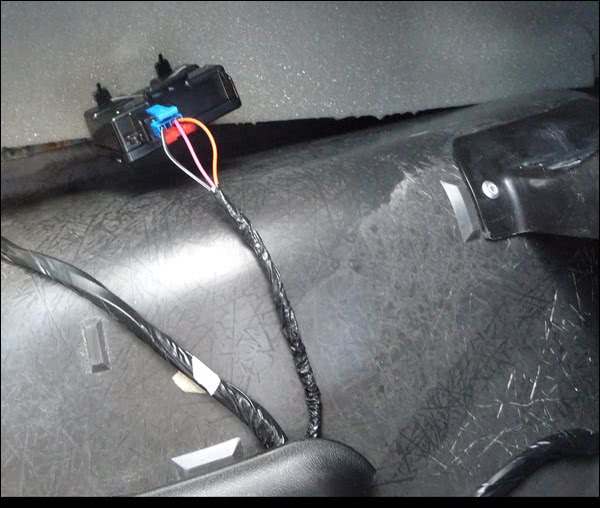
I located the RCDL module in the left rear compartment (Figure 9) and checked the wiring to it before condemning it. It’s not uncommon for a bad module to back feed power or ground into the network causing communication failures. There were three wires at the RCDL module consisting of power, ground, and a signal line. When I checked the ground, it was elevated at 12 volts. This to me seemed like an open ground, and the 12 volts was probably back-feeding from the module 12-volt feed line. I decided to back probe the wire with a ground. When I did, I saw an arc. This was not a bad ground, but rather a12-volt feed shorted to the ground line within the module, or externally to the ground feed line from another source. I immediately unplugged the RCDL module, but the 12 volt short remained on the ground feed line.
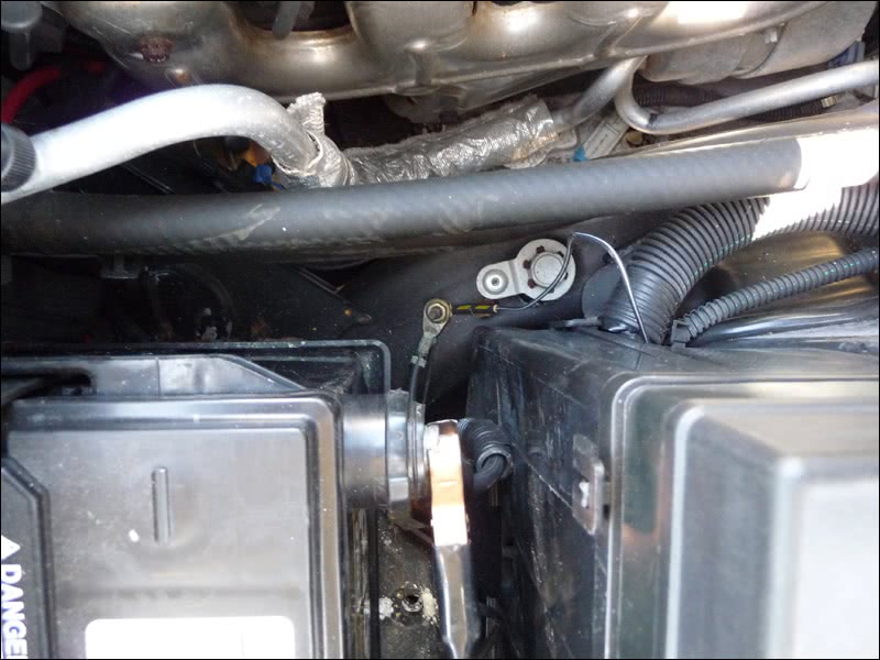
I followed the ground wire back through the vehicle and it led me to a juction block in the right kick panel (Figure 10). A closer inspection here showed a 12-volt feed line next to the RCDL ground (Figure 11). This line bridged itself to the ground feed and burned the ground all the way back to a firewall splice where it was stopped by a heavier gauge wire that led through the firewall out to the the frame rail in the right-side engine compartment (Figure 12). The splice gave in, but the heavy-gauge wire leading back to the frame well held its ground (no pun intended).
What a turn of events in this diagnostic delemia. It was amazing to me that none of the controllers, or my TECH II, got damaged from 12 volts shorting on the data line. I can only guess that most manufacturers prepare scan tools and onboard controllers for these events and build in a fail-safe system to prevent component damage. You just don’t know what to expect anymore. You can’t just condemn the computer when there’s no communication. It’s vitally important to check all powers and grounds at the controller in question. Never leave out the possibility of a shorted to power or ground data line. I hope this story has inspired you!
by John Anello, “The Auto Tech on Wheels”


0 Comments