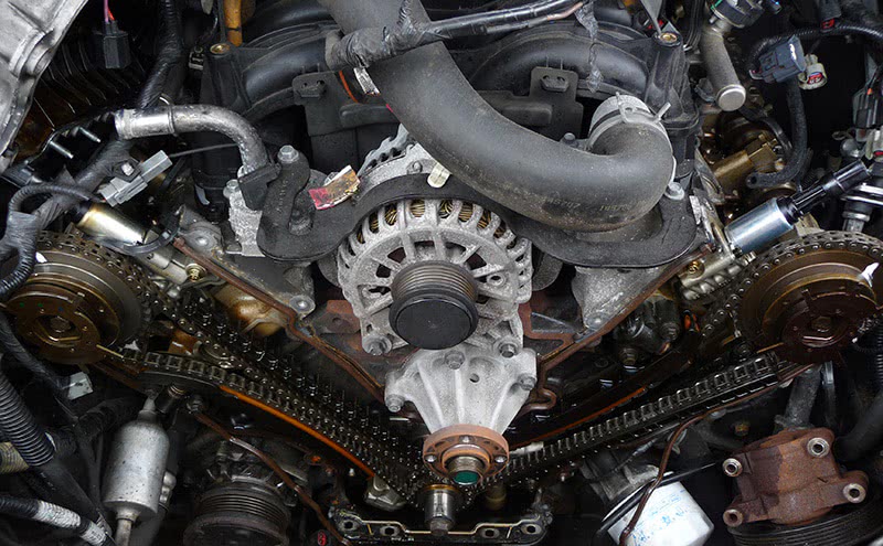
I was called to a shop on a 2006 Lincoln Navigator (Figure #1) 5.4L with a complaint of a rough-running engine. The techs pulled some O2 sensor lean and rich codes along with some variable valve timing codes. They were not too familiar with the operation of the variable valve timing system on this vehicle, so they decided to get a more in-depth diagnosis before making any major decisions on where to go.

When it comes to variable valve timing systems, there are indeed a lot of variables involved. The basic strategy of the PCM is to determine how much duty cycle it will provide to each cam actuator solenoid to allow oil pressure to pass through the cam actuator thus moving the camshaft gear on the end of the camshaft to accommodate an advance or retard position relative to that of the crank. A lot can go wrong, such as a sticking solenoid or actuator, or even clogged oil passages. Blame poor oil maintenance, or wear and tear from high mileage. There are also electrical failures such as open or shorted actuator solenoid circuits, or a possible failure of the solenoid driver within the PCM.
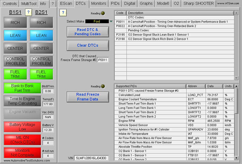
When I arrived at the shop I hooked up my generic Escan tool just to pull and verify the codes that had already been retrieved (Figure #2). There were P0011 and P0022, which related to the position of Bank #1’s camshaft being over-advanced, and Bank #2’s camshaft being over-retarded. The PCM in this vehicle was using two camshaft positioning sensors to perform a check and balance of the variable valve timing system. The command was given to each camshaft to move to a certain position while the PCM had the ability to validate if the camshaft sprockets were actually in the correct commanded positions. There were also O2 codes P2195 and P2198 stored in memory stating that Bank #1 was running lean while Bank #2 was running rich. These O2 codes were in the mi,x but you need to keep in mind that an engine with mechanical or hydraulic problems can easily mess up the fuel trims and create a lean or rich condition. So, I decided to home in on VVT.
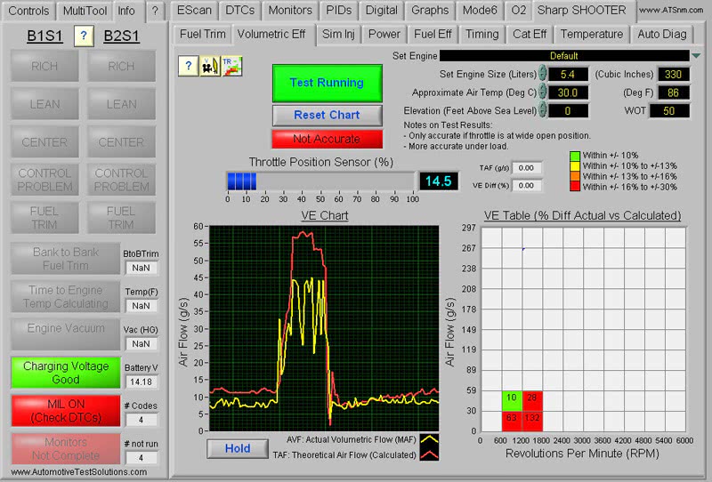
I knew that a valve timing issue would easily show up in a volumetric efficiency test without my getting too intrusive. I already had the Escan tool hooked up, so it was just a matter of plugging in some criteria information to test the volumetric efficiency. I set the engine size to 5.4L, ambient air temp to 86 deg. F., and my elevation at sea level. I next power braked the engine to wide open throttle and graphed my readings within the program (Figure #3). The red graph represents the theoretical air flow as calculated by the program, while the yellow graph represents the actual volumetric flow. By looking at the yellow graph you can see that not only was the volumetric efficiency of this engine low, but the air volume was moving in and out of the MAF sensor. I have seen this erratic air flow many times before using this VE graph and it is usually a clear indication that the engine either has a clogged exhaust or a valve timing problem where the intake valves are not properly closing as the piston is reaching top dead center of the compression stroke.
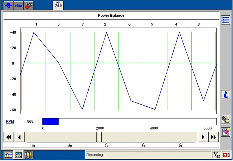
To stay in the driver’s seat of diagnostics and still not being too intrusive, I decided to hook up my Ford IDS scan tool for some enhanced engine diagnostics that the tool claimed to perform. My first step was to verify which cylinders were creating the roughness in the engine. This I did by using the power-balance mode (Figure #4). In this mode I was able to see the PCM monitor the speed of each individual cylinder’s crank throw by means of the crank sensor. You can see that cylinders #5, 6, 7 and 8 were all below the zero line. Normally this pattern would run close to the zero line with slight deviations of plus or minus 5% and any large “V” spike below the zero line would indicate a misfire. Taking into consideration that cylinders #5, 6, 7 and 8 all share the same Bank #2 cylinder head, I was leaning toward a valve train problem with that bank.
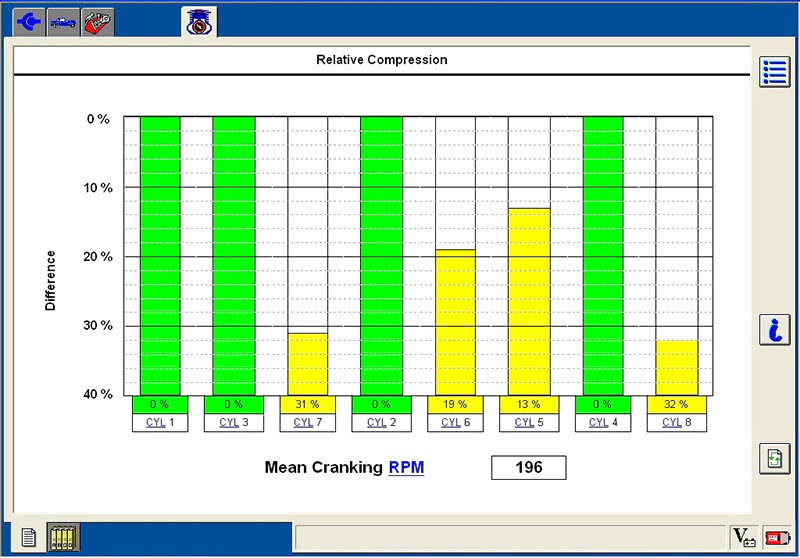
I moved on to the cranking compression test that I have found to be a solid Ford IDS procedure that has yet to let me down. Again, this uses the crank sensor to determine the speed of each cylinder as it monitors the slow-down of crankshaft speed as each piston comes up on the compression stoke. A weak cylinder doesn’t slow the crankshaft as much as much as a stronger one does, thus showing up as a low-compression cylinder. As I cranked the engine at wide open throttle to prevent the injectors from firing, I captured a cranking compression chart (Figure #5). You can see by the chart that cylinders #5, 6, 7 and 8 all had low compression as compared to Bank #1’s cylinders. It’s convenient that this can be done without ever having to pull the spark plugs and measure the compression of each cylinder with a mechanical gauge. This is technology at its best!
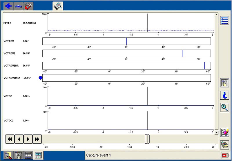
The validation process was all pointing toward a possible jumped timing chain on Bank #2. It was just unlikely that one head would have four bad cylinders with leaky valves. The common cause of low compression in four cylinders in the same head would most probably be a valve timing issue. I now wanted to do one more check to find out what the PCM was seeing when it set the variable valve timing codes, so I decided to look at the camshaft timing parameters for each bank on the scan tool (Figure #6). By looking at the data with the engine idling in its rough mode, I could plainly see VCTADV for Bank #1 was at 0 degrees at idle, but the VCTADV for Bank #2 was close to 60%, indicating that the cam sprocket on Bank #2 was out of correlation to the crankshaft. At this point I had gathered enough information to validate the removal of the front timing cover.
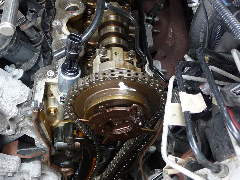
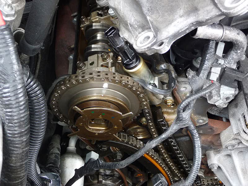
I went back to the shop the next day and the tech had pulled the timing cover and lined up the crank so the keyway was up at the 12 o’clock position (Figure #7). I placed whiteout on both cam sprocket marks and I could see the driver cam sprocket timing mark was properly lined up with the center of the camshaft hold-down cap (Figure #8). When looking at the Bank #2 cam sprocket (Figure #9), I could easily see that it was off by a few teeth. The timing chain had jumped, which caused the engine to run very poorly and the PCM to set timing position error faults. I felt good about my findings because I did not want the shop to go through all the work of ripping down the front of the engine just because it “felt” like a timing chain issue. I had to be sure on this one.
It was a very interesting turn of events to be able to literally sit in the driver seat and do performance tests and mechanical diagnosis using only scan tools. I sat comfortably inside the vehicle and didn’t even have to open the hood or get my hands dirty. I must say that as these engines and operating systems get more advanced our diagnostic jobs get physically easier, if more intellectually challenging. You just can’t be too quick to jump the gun. Rather, set up a series of test procedures for yourself to better home in on the problem. This will lead to a successful diagnosis with very little time wasted.
by John Anello, “The Auto Tech on Wheels”


0 Comments