

Sometimes in the world of diagnosing BMW vehicles we run into “That Car.” Yes, you already know what I’m referring to — the one vehicle that tests your patience, your knowledge, your understanding of theory, and your customer management skills.
They used to say those cases were only 10-20 percent of the service mix equation, but today this paradigm is rapidly changing.
The onslaught of engineering complexity, along with the explosive growth in the number of active and passive modules, AI and software complexity running in the modern vehicle platform have all combined to create a trend toward “That Car” being up to 20 and 30 percent of the diagnostic and repair mix today.
These vehicles present a challenge to shop owners, customers, and technicians more now than ever, because the diagnostic calls we are having to make all over that vehicle, no matter the system we are working on, often cost into the thousands of dollars.
This means that getting through a simple driveability concern (or a seemingly simple one…) can turn into a big problem for the shop and the customer very quickly if we are not well studied in our electrical theory and testing strategy on BMWs or any other vehicle make we service these days.
Because electronics, sensing, and computer actuations drive and control virtually every mechanical component in the vehicle, and indeed even allow the vehicle to control (and drive) itself, technicians are now faced with vehicles that contain six to eight different networks supporting five different protocols and up to 100 or more separate active or passive modulized components, all talking on the various networks to make things work seamlessly, safely, and smoothly… until they don’t.
Every one of us is familiar with some form of “That Car,” aren’t we? But when working with any vehicle built after 2010, especially a BMW vehicle that fits this explosive technology criteria, we’ve got to sharpen our diagnostic skills and pay attention to the small clues.
Too much can go wrong for a tech today, as compared to 15 years ago, when “only” 11 modules on a single bus line was considered a huge technological leap and a tough diagnostic challenge.
Yeah, right. Just try to be a tech today, and chase an intermittent problem affecting three or four interconnected systems simultaneously. Try to figure out the vehicle that has ONE single errant 1 or 0 in its millions of lines of computer code and worse, try to explain to that customer why the vehicle suddenly decides to lock its doors on left turns, on Tuesday nights, going uphill when the moon is blue.
Try to explain how after the vehicle depowered the throttle and the car coasted to the side of the road; then explain how it is now fine and acting like nothing happened after it was towed into the shop, and yet drives perfectly for the entire three days we have the car, only to fail on the customer again as soon as she picks it up from the shop. “Like sands through the hourglass, so are the days of our lives…”
We come together at BIMRS every year to network and study all things BMW, which is of critical importance if we are to remain relevant as technicians and European repair shops in today’s world.
Here’s how one particular (and real) case study went
By the way, this old 2007 vehicle “only” has 3 networks and 39 modules on board…
A 2007 E70 came in on the hook with a throttle default and dead-pedal, so to speak. It came from another repair facility, having been towed in there too, but the first shop did not solve the issue. There were however, some new parts on the car.
The vehicle had 2 DTCs, a 2CF9 indicating Throttle Valve Potentiometer 1 Circuit Fault, and the other DTC, 2CFB was indicating Throttle Valve Adaptation Value. This DTC was setting because the throttle valve wouldn’t pass the initialization for reasons explained and outlined below.
To shorten a long story, the previous repair attempts had the technician replacing the MAF sensor, and after some further diagnosis, a new throttle motor was installed. This is when the challenges started.
The new throttle motor would not accept the teach-in procedure. Wouldn’t even run the process in fact. Every tool in the shop was tried. It just kept failing every time the throttle learn command was attempted.
Frustrated, the technician went over his work again to be sure nothing was awry in the connections, mounting, or installation of the part. Nothing. UGH. Same condition again! Same codes, and the throttle will NOT learn no matter what.
So the original throttle valve went back in. Same thing. The ORIGINAL ETM won’t even relearn now. Huh? Uh-oh.
In looking up the DTCs and test plans for this code, we notice a pretty clear explanation for how the DME sums and uses the two Potentiometer 1 and 2 signals; it’s pretty simple in concept.
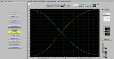
Throttle POT1 signal goes low to high from 0 to 5.0 volts, and Throttle POT2 signal goes from high to low, from 5.0 volts, to zero volts.
Cool. The DME supplies all three legs of each sensor circuit with power, signal return circuit, and ground. The power flows through the sensor, and back to the DME, with the signal on the sensor return.
Because the DME supplies the power and samples the return, it has reference of the EXACT voltage being supplied to the sensor circuit. The two potentiometer signals are then summed by the chip and compared at the point of transition as they switch from high to low.
The signal voltage summed at this point must match the supplied voltage EXACTLY or the system will set a fault, disable the throttle, and fail the initialization. Which is what was occurring in this case.
Next, we checked the live data PIDs on the X5 for Potentiometer 1 and Potentiometer 2 signals and, sure enough, the data PIDs summing the two potentiometer signals added up to only
4.3 volts, not source voltage.
A clearer understanding of the two DTCs is now coming into focus. The 2CF9 has been reporting the Potentiometer A Circuit Fault all along, and the DTC won’t clear.
The 2CFB describes a fault where the throttle learn procedure won’t run, and now we know that this is caused by the potentiometer A circuit fault, the resultant corrupt data that the DME sees, is forcing a failed initialization of the Throttle Control Valve (ETM) every time.
Now, exactly where is this fault occurring? What is causing this corrupt data? With a negative voltage reading on the Potentiometer A PID, which should not be occurring in any case, we’ve got a voltage problem here somewhere in the circuit.
The next step was to hook up the scope, and start acquiring the voltage and signal data from the potentiometer sensor circuits themselves. The sensors both had 4.99 volts strong at the pedal sensor module itself. The ground was also verified while the circuit was operated and no voltage drop appeared on the ground leg of the pedal sensor either.
A sweep test was then performed on both potentiometers. Our signals swept from 5.0 to zero, and zero to 5.0 nicely, with no dropout characteristics, so the potentiometers – the pedal sensor passed beautifully.
Now, we uncover the DME, remove the connector covers and back probe the scope directly into the circuits at the DME connector with two channels, and keep two channels on at the sensor end. We conclude that the analog voltages measured are equal and steady at both ends of the circuit.
The DME is then disconnected, the throttle valve sensor is disconnected and the two signal wires are electrically loaded and voltage drop tested independently from the two modulized components.
Voltage drops recorded were 0.002 volt drop on one wire and recorded a 0.001 volt drop on the other, proving beyond a doubt that the wiring was intact, analog voltage supplied by the DME was good, and said voltage was in fact getting all the way back to the signal circuit connector at the DME, adding up to exactly 5.0 volts.
At this point, since everything is apart, we decided to pin-drag each of the connectors on both ends of the circuit, just in case. After this was done, everything was reassembled so we could resume testing.
But what next?
Here we have a vehicle exhibiting this condition and, after hours of physical testing, literally every signal and analog voltage circuit we could test that was related to these faults has been verified as fault-free and yet, we still have this condition.
Let’s return to the scan data we were observing, and apply some math to understand the difference between what the DME sees here, and what the analog voltages and scope activity are physically telling us. Herein lies the answer to the problem with this X5.
We decided to monitor the scope and the scan tool simultaneously so we could visualize what was going on “inside the box.” We seemingly had a logic issue, because copious physical testing proved the actual circuits and sensors were found to be working perfectly.
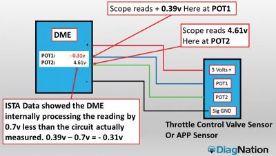
When we looked at this circuit from both angles and did the math, we found that the issue was that the Potentiometer A circuit’s data PID was exactly 0.7 volts – seven tenths of a volt less than the actual sensor signal voltage available at the DME pin. This was causing a negative voltage reading on the DME’s Potentiometer 1 PID. Logic said NO-GO, initialization failed, and the DTCs set immediately.
In looking at how these circuits do work inside the box, we can quantify to the highest degree possible what has happened here. What is meant by the highest degree possible, is that as technicians, we can only know what we know, and do what we can do.
But what we do know is that we can use our knowledge of how electrical components work (theory) and how electronics work (theory) to take the analog readings and use them to confirm without a doubt that the failure that we are seeing IS inside the box, the DME.
Why are we going through all this? Because the DME is a $2,500 call or more, when it’s all said and done. And there has already been a good chunk of money thrown at the car to try to fix it.
This X5 needs a DME. We just needed to be sure, as close to 100 percent as possible, that this was going to fix the car, based on the situation with the client.
Why can we be so sure that the DME will correct the fault and the 2 DTCs?
If we have perfect analog readings up to the DME connector, which is really as far as we can go testing-wise, how does the module actually process this potentiometer signal, and how does the DME know what the voltages are on each leg of Potentiometer A and Potentiometer B?
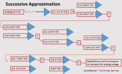
Inside modules, sensor signals are translated from the analog world (our world) to the digital world (the DME’s world) by a device called a comparator. The comparator is made up of multiple transistors, networked in such a way as to be able to interpret that analog voltage very accurately and very quickly using strings of transistors configured to split down the voltage in chunks, to target and interpret the analog voltage using feedback circuits.
Comparators, for our purposes, provide an almost instantaneous conversion of that analog voltage to digital binary information for the DME’s logic chips to use. The converted data is then processed through the programming algorithm’s truth tables, and the TCV/ETM will then be driven by the processor’s input to the ETM’s H-bridge controller, which contains the current drivers.
In addition, most all sensor circuits contain a signal sampling resistor that taps off of the sensor input. This sample is compared to the inputs at the chip level by monitoring voltage dropping across the sensor circuit and provides feedback to the chip for logic and fault detection.
Anyway, back to our vehicle under test. Our physical testing caught that the actual analog input voltages were exactly what the DME wants and expects. However, the DME in this case has a transistor problem inside the module.
How do we know specifically it is a transistor, even though we don’t have micro-board repair ability?
Because of the amount of voltage that is missing from the Potentiometer A circuit data PID inside the DME.
A typical transistor requires 0.7 volts of forward bias to turn it on. And as it happens, once we took the true analog voltage readings at the DME, and overlaid this data with the scan tool data PID, we were missing exactly 0.7 volts.
Because the analog signal was correct, right into the DME’s input pin, we also knew that the sampling resistor inside the DME would essentially be seeing the correct voltage too, so the issue was further on down the line. Where, exactly? Most likely, in the comparator (transistor stack) in the DME chip processing the sensor signal.
The bottom line on the X5? A DME fixed the condition.
Understanding how the DME or any other module processes signals, along with some robust physical testing and persistence helped us to not only identify, but to find, isolate and prove the cause of the fault on the X5 accurately without replacing any further parts on a guess and a prayer.
During our BIMRS class on PWM and 3-Phase Diagnosis in BMW cars this October, Eric Scharping and I will be carrying the sensing and circuit diagnosis techniques outlined here, over to the output side, as we study Pulse-Width Modulation, Smart Motor Controls, and 3-Phase electrical applications in BMW vehicles.
We believe the tough ones can be solved efficiently when we put BMW service information together with a scope, a solid understanding of theory, and a strategic and careful approach to your test plan.
Enjoy the BIMRS Virtual event this year, it is going to be AWESOME!

0 Comments