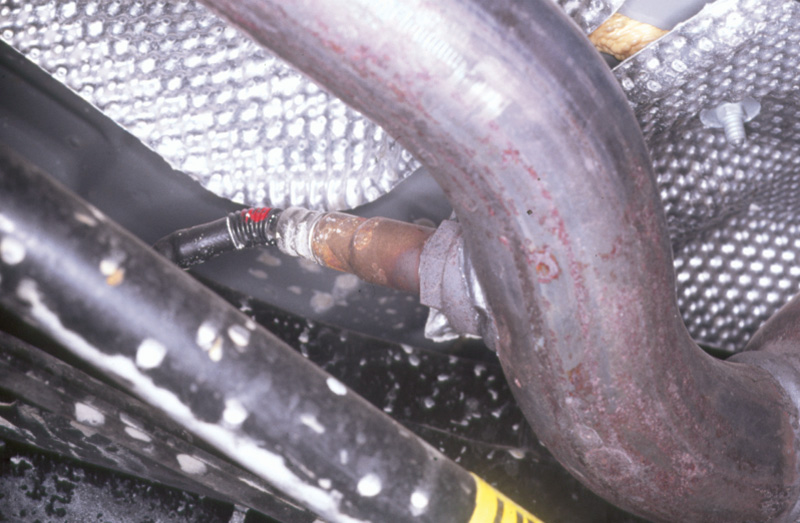
The oxygen sensor is the heart of the mixture control system. Because of the unique properties of its zirconium ceramic and platinum catalytic surfaces, it reflects the amount of residual oxygen in the exhaust with great precision, allowing a similar precision in the mixture calculations.
We want reliable, fuel-efficient cars, yet we also want breathable air. So we control vehicle exhaust because all the undesired emissions are either unburned (that is, wasted) fuel or the more or less unpleasant byproducts of combustion. In this issue of StarTuned, we’ll take an overview of the emissions controls on Mercedes-Benz cars, and in later issues we’ll pinpoint different emissions subsystems and how they’ve changed over time. As usual with things automotive, you have to know how they work when they do work before you can diagnose or repair them when they don’t.
While there are various ways to sort emissions controls, this is the set we’ll use here: mixture controls, combustion controls, exhaust controls and fuel vapor controls. You may argue that a PCV or an EGR really affects exhaust rather than mixture, but as long as we have clear what each subsystem does, where we list it here won’t make any work difference on the shop floor.
Mixture Controls
The major role of emissions control systems is keeping the fuel-air mixture in the stoichiometric or ‘Goldilocks’ proportion, not so rich there is still fuel in the exhaust, not so lean the cylinder misfires, but just right to allow the catalytic converter to clean the exhaust as much as possible. What’s more, we’d like to derive some transportation use from the combustion, too.
A mixture too rich wastes fuel and spills it into the exhaust (to say nothing of washing down the cylinder walls, diluting the crankcase oil and thus accelerating mechanical wear). Too lean also wastes gas, spilling it into the exhaust (because the misfiring cylinder’s gas just blows through the pipe and the other cylinders that don’t misfire have to take up the torque slack by burning still more fuel). Not much of a choice between these options!
That was why carmakers abandoned carburetors and opted for a fuel injector in each cylinder’s intake port. Fuel mixture concentrations often vary by as much as 60 % on carbureted engines, even with the elaborate measures eventually taken to try to equalize delivery to the cylinders. That meant some cylinders ran too lean while others ran too rich – in the same engine at the same time! If you think fuel injection systems are complex, just look at the carburetors on any model vehicle in the last year before they were replaced with injectors. Do you fancy, say, tracing a vacuum-related problem on one of them? How about an intermittent partial-throttle surge?
In one stroke, port fuel injection reduces that variation and complexity tenfold. You’d have to have individual carburetors for each cylinder, all of them perfectly synchronized, all perfectly adjusted, all of them with zero linkage slack or play – all to approach the mixture precision the ported injectors have automatically, right out of the box. And individual carburetors are much more complex and trouble-prone than individual fuel injectors. So engines with individual carburetors for each cylinder didn’t happen on cars. Clearly, in the real world they couldn’t have.
There are two varieties of port fuel injectors, pulsed or continuous. Pulsed injectors usually share a largish pipe from which a row of them draw their gasoline, the fuel manifold or fuel rail. Its size comes from the need to have enough pressurized fuel in a single reservoir (or pair of reservoirs on a V-form engine) that no single injector’s pulse will drop the reservoir pressure enough to affect delivery to the upcoming cylinders. Pulsed injectors are also electromagnetic valves, so each one has an electrical connector. Power is constant; ground is pulsed.

Later model vehicles use multiple oxygen sensors, with those downstream monitoring the effectiveness of the catalytic converter. If the converter works properly, reducing and oxidizing the undesired elements in the exhaust, the downstream oxygen sensor should exhibit little or no pattern. When it starts to echo the signal from the upstream sensor, the catalytic converter is out of business.
Continuous injectors use long, separate tubes, steel lines like Diesel injection lines or even braided steel lines, one for each injector. Each injector’s fuel line extends from the fuel distributor to the individual fuel injector, and they are ordinarily of equal length so the resistance to flow is identical for each cylinder. These lines do not need to be nearly so thick as a fuel rail because fuel moves smoothly through them to only one cylinder and at a relatively constant speed without pulses. The flow volume varies with engine load and speed, but nothing that happens on one injector’s hydraulic circuit necessarily affects another’s.
Mercedes-Benz has used both types of injector. While the company’s automotive history includes such exotics as the Diesel-like direct, into-the-chamber injection system of the Gullwing SL, the earliest recent fuel injection systems were versions of the Bosch D-Jet, spraying fuel with each cylinder cycle and using air pressure in the intake manifold as the primary input to calculate injector on-time. And the on-time duration corresponds directly to the amount of fuel injected, just as on later pulsed injection systems.
The continuous injectors are what you see most often, components of the various K-Jet systems on the cars. Fuel sprays from the K-Jet injectors as long as the engine is running, but its volume changes to correspond with the amount of air entering the engine at the same time. The correspondence derives, at least in the first systems, entirely mechanically through the fuel distributor, essentially a complex hydraulic valve activated by a lever at the extreme end of which is a round plate in a funnel, pushed by the incoming air.
The early, plain-vanilla K-Jet systems were much better than carburetors in emissions terms, but most cars built in the last twenty years now employ feedback systems based on an oxygen sensor in the exhaust. After all, it’s very well to be able to control fuel mixture with great precision, but you need some constant source of fresh information about the effect your mixture changes have on the combustion.
The oxygen sensor once warmed up and at work, functions almost like a battery, generating a very low amperage, very low voltage signal inversely corresponding to the amount of oxygen left in the exhaust stream. The more residual oxygen there is in the exhaust, the lower is the sensor’s output voltage; the less residual oxygen there is, the higher.
We don’t have space this month to go into exactly how the oxygen sensor manages this feat. Briefly, it is ‘transparent’ to oxygen ions – O2 molecules separated into positively charged individual oxygen atoms – but not to anything else. As the oxygen atoms, properly described as ions because after O2 separates into two atoms of oxygen each carries a small positive charge, as they travel through the sensor’s ceramic thimble, they carry electrons with them, forming a small voltage and current. The signal that electron transfer generates is enough for a computer to trace and to use for final adjustments to the fuel mixture either richer or leaner, as the state of the residual oxygen in the exhaust indicates. When working properly, the system should include an oxygen sensor cycling regularly between about 0.3 volts and about 0.9 volts.
As the signal cycles, the mixture the computer commands also cycles, and the resulting combustion mixture oscillates back and forth across the ‘stoichiometric notch’ the range of mixture producing the least exhaust emissions once the catalytic converter finishes oxidizing and reducing the gasses. It comes close to the mixture that would yield the highest fuel economy, too, but we and every other society that has concerned itself with the question have chosen to favor breathable air over the last iota of fuel economy.
Later model cars use oxygen sensors with internal electric resistance heaters to get them functional more quickly (they have to reach about 600 degrees F to allow oxygen ions through and get to work producing a signal) and to keep them working under low-temperature, low-engine-load conditions, like extended cold-weather idle. Even newer cars use sets of multiple oxygen sensors, to monitor the mixture of different banks of V-form engines more accurately and to monitor the effectiveness of catalytic converters. While the later computer uses these signals in more complex ways (not only to monitor the function of the converter but for even more precise fuel mixture control), the sensors themselves are not different from the original ones. The oxygen sensor, or the set of multiple oxygen sensors on cars so equipped, are the fuel injection system’s last look at the product of its previous work and the basis for the last calculations of the amount to inject next.
On the KE-Jet systems, those using continuous injectors in conjunction with oxygen-sensor feedback and computer controls, the final device for adjusting the fuel-air mixture is the electrohydraulic actuator or EHA. It is electric in that it is a variable-strength electromagnet, changing the force on a valve that leaks fuel from one side of the fuel distributor metal diaphragm to the return circuit – or that does not, depending on the command from the computer. This command takes the form of current, of amperage. An electromagnet responds to current only, not to voltage, so that is what you measure to check the system (it should fluctuate in response to the oxygen sensor).
Keep in mind while the EHA does not respond to voltage, it does respond to polarity, so you need either an ammeter that reflects that electrical property or a voltmeter to supplement your ammeter. Many cars will use the EHA to shut off all fuel delivery during closed-throttle deceleration under normal driving circumstances.
There are no specifications to match current oxygen sensor output with EHA current because there are many other factors involved, including the history of where the signal and the command were a moment ago. But if you find a cycling correspondence between them, a correspondence in the range you’d normally expect to find from previous, known-good cars you’ve observed, the system is adjusting the mixture correctly in response to the feedback signal. If not, it’s time to start digging.
Where to dig when working on a particular system we’ll cover in detail in later articles. In general, you want to confirm that whatever signal the oxygen sensor generates gets to the computer untampered with by interference from high resistance, shorts or spurious electromagnetic induction and the like. The same applies to the command from the computer to the EHA; it should arrive at the actuator with the same electrical properties it left the computer. In either case, if things are otherwise, check the connecting harness. This is the usual computer-diagnostic procedure of determining whether the information coming in is good and whether the information going out is at least plausible. While it is unlikely that a control unit is defective, if you find one with good information getting to it but bad or no commands coming out, you may have found one that has failed.
The later Mercedes-Benz cars use individually pulsed fuel injectors rather than continuous. The reason for this is twofold: First, there is an optimal moment to spray the fuel so all of it vaporizes and flows immediately into the combustion chamber rather than condensing on the intake manifold walls or the back of the intake valve. Second, there was still some variation in the flow from one continuous injector to the next because whatever the level of the manufacturing care, there are tolerance variations affecting fuel delivery pattern and volume. There are with the individually pulsed injectors, too, of course, but you can slightly vary the pulse command one injector at a time to correct for that.

The EGR switchover valve controls direct actuation of the EGR valve itself. The conditions under which the system uses EGR vary from model to model and from year to year. In fact, those conditions vary from place to place as well: In some model years there were differences for California-specific models from the federal. The only way to be sure to get the correct part is to get it from the only source of accurate information about which part goes on which model.
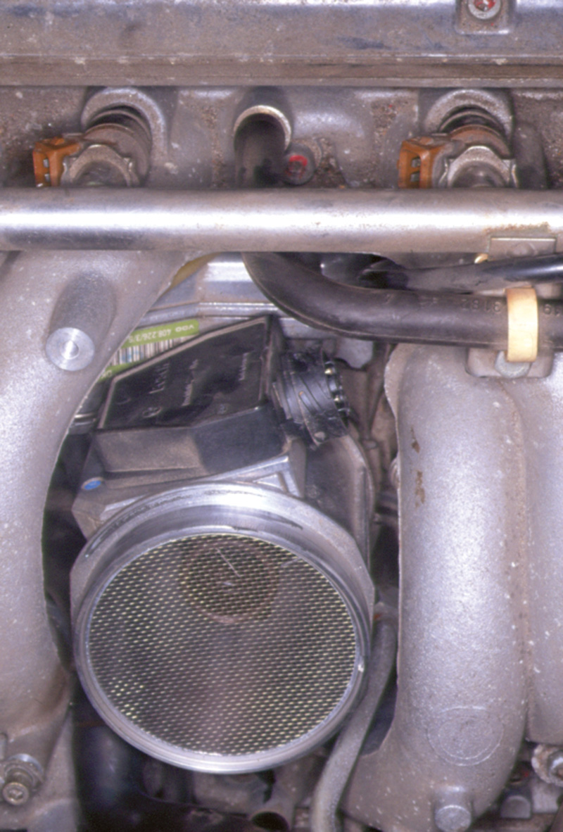
The K-Jet and KE-Jet systems measure intake air by the deflection of the lever at the air horn. Later systems like Motronic measure air with a hot-wire system. This more precise measurement calculates the mass of the intake airflow by the amount of heat carried off from a special platinum wire in the airstream. More air carries off more heat and vice-versa. At the heart of the sensor is an electrical circuit called a Wheatstone bridge, an array of fixed and variable resistors that detects small changes in resistance very accurately. The two variable resistors in the sensor reflect the temperature of the incoming air and its volume. There is not a return signal to the computer directly; instead the computer internally monitors the current required to keep a voltage in the sensor constant.
Hot-wire sensors include a ‘burn-off’ cycle. When the engine is first shut down, the computer will send a high current through the wire for about a minute to burn off any condensed fuel vapors, bits of paper filter element or whatever may have fallen on the wire. Obviously, anything that might block the flow of air over the wire is going to render it inaccurate as a measure of the airflow mass.
Measuring air mass is an inherently more accurate way to calculate the incoming air when preparing the mixture because a mass does not need correction factors for temperature, humidity, altitude or any of the other variables. Mass is a direct measure of the number of molecules in the intake, and the number of oxygen molecules is a constant fraction of that. Fine-tuning the mixture, naturally, falls to the signal coming from the later models’ oxygen sensors.
Combustion Controls
While preparation of the intake mixture is the major technology affecting the vehicle’s emissions, there are two measures more specifically affecting what happens in the combustion chamber itself: exhaust recirculation and variable valve timing.
The exhaust gas recirculation (EGR) system exists to prevent or reduce the formation of oxides of nitrogen in the combustion chamber, some of which chemical combinations degrade the air quality. Nitrogen constitutes about 80 % of the air and ordinarily (lucky for us!) does not combine with oxygen. But at temperatures in excess of 2500 degrees F, such combinations can occur. These temperatures can occur in combustion chambers when the mixture is relatively lean and the load is relatively high. Unfortunately, these are the very conditions we’d like to see during sustained high cruise, because they produce the best fuel economy.
EGR systems use metered amounts of exhaust mixed into the incoming mixture almost like the carbon rods in nuclear reactors – just there to slow the action. Any inert gas, like helium or argon, would work as well; but exhaust is already on hand, costing nothing. The effect is to slow combustion, but not affect it otherwise. Burning the same fuel over a longer period clearly yields lower peak temperatures, the very objective we were after. Adding recirculated exhaust to the intake also has the minor positive benefit that it reduces the intake manifold vacuum (or equivalently, that it increases the intake manifold pressure), thus reducing the pumping losses of the engine. So EGR can have a small but beneficial effect on fuel economy.
Over the years Mercedes-Benz has used a variety of different EGR systems, so we can’t detail all of them here. Perhaps the most common problem you may find, particularly on vehicles that have been in use for a long time, is the gradual buildup of deposits in the EGR passages. This is a natural and unavoidable consequence of exhaust, which contains the deposits as leftovers from the combustion (EGR picks up the exhaust right out of the combustion chamber, not downstream after the converter).
Exhaust Controls

Each of the sensors in a fuel injection system serves to modify the calculation of how long the next fuel injection will last, and thus how much fuel will be injected. Sensors like the throttle position sensor or the mass airflow sensor put the system within the large-scale range of the correct mixture; information from the oxygen sensor provides the last modification of the injector on-time algorithm.
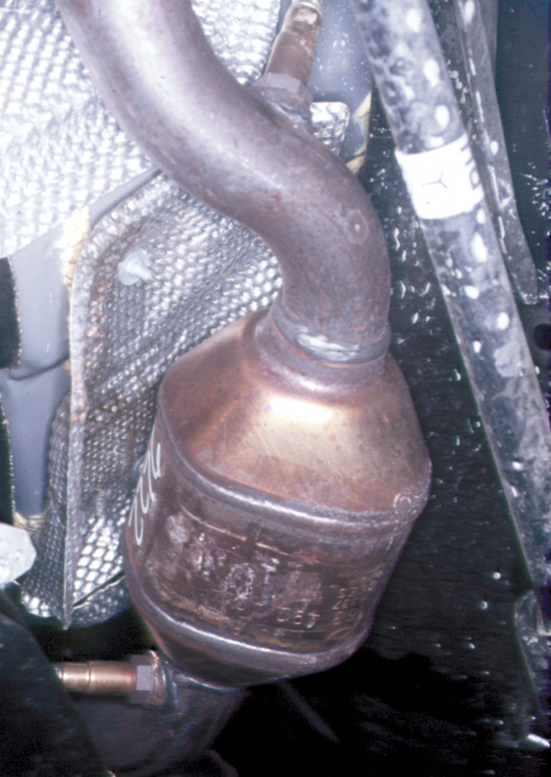
One constant on the exhaust system of every car for the last twenty years is the catalytic converter. Current cats are three-way oxidation/reduction versions that both oxidize any residual fuel in the exhaust and reduce, i.e., neutralize any of the NOx gas we discussed above in the section on EGR. These chemical functions usually occur alternately, that is, the converter oxidizes while the engine runs on the rich side of stoichiometry and then reduces when the mixture oscillates over to the lean side.
Over the last years, carmakers have installed additional oxygen sensors downstream of the catalytic converters. The principal function of these sensors is to monitor the catalytic converter. Their signal should wander vaguely over the sub-one-volt range rather than oscillate regularly like the otherwise identical oxygen sensors ahead of the cat. But they are also available to the computer as inputs for calculating the fuel mixture in upcoming combustion events.
But upstream of the catalyst, even upstream of any pre-cats the car may have, is the air injection system found on many vehicles (emissions equipment varies depending on the emissions regulations in effect in the place and at the time where and when the car was first sold). An air pump, when one is installed, pumps air directly into the exhaust manifold, right behind the exhaust valves where the exhaust is at its hottest. The major function of this is to clean the exhaust as much as possible when the engine first starts cold, before the oxygen sensor feedback system is at work, before the catalytic converter is warm enough to treat the exhaust. The air blown into the exhaust manifold at that point provides enough oxygen to burn the residual fuel necessary because a cold engine requires a rich mixture to fire dependably. This situation changes rapidly as the engine warms, but cold-startup emissions problems remain one of the combustion engineer’s greatest challenges, and thus one of the automotive technician’s, too.
Vapor Controls
It’s been said that on a new car with everything working properly, the major source of air pollution is the outgassing of certain hydrocarbons from the new tires and the evaporation of the last of the factory oil sprayed into the tire mold to release the finished tire after the rubber cools and cures. New rubber certainly has a characteristic smell that goes away as the tire ages. And rubber has many hydrocarbons in it.
But the kind of evaporated hydrocarbons we worry about don’t come from road rubber, but from gasoline. This is a problem that can’t go away with improved fuel blending or refining, because gasoline has to vaporize before it can burn in a combustion chamber. So there’s a conflict between the need to get the fuel to evaporate as quickly as possible after it leaves the nozzle of the fuel injector and the need to prevent its evaporation when it’s in the tank waiting for use. Fuel lines, the filler cap, the pump and filter and all the fuel injection apparatus under the hood are potential sources of evaporative emissions.
The major system to prevent a car from causing air pollution while it’s sitting quietly and cool with the engine off is the charcoal canister system. Pneumatic tubes from the vapor-filled top of the fuel tank lead to a canister filled with specially activated charcoal pellets. Fuel vapors adsorb – yes, that word’s spelled right – onto the surfaces of the charcoal pellets. They do not dissolve or mix with the charcoal; they merely cling – adsorb – to the surfaces. Then once the engine is running the next time and has reached normal speeds and temperatures, the purge valve opens and flushes the charcoal canister out with fresh air, venting the stored fuel vapors into the intake manifold and combustion chambers where they are usefully burned.

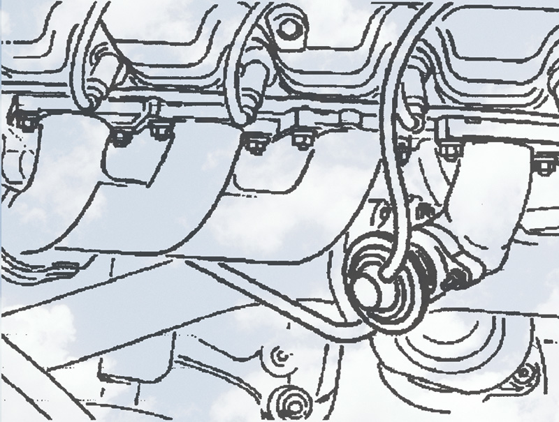
The EGR valve itself need only collect exhaust from one runner since there is no reason to get a mixed sampling of the exhaust. As long as the cylinder used does not misfire, it produces an exhaust that will be effectively inert in the next combustion cycle, so the factory puts the valve in whatever place is easiest to reach without interfering with other components.
The major service problems with the system come from two sources: leaks that develop in the pneumatic system, connecting tank to canister and canister to valve to manifold, and from car owner mistakes. The latter occur during refueling the vehicle. On older cars, before carmakers were onto the trick, some drivers would try to fill the tank to the point when they could see liquid fuel at the brim of the filler tube. That required nursing the fuel filler nozzle to squeeze in the last few cups of fuel. It also meant liquid fuel could sometimes move through the pneumatic lines to the canister.
The canister can handle fuel vapors handsomely. But it can’t handle liquid fuel at all because the pellets will partially dissolve and form a solid monolith, incapable of fuel vapor adsorption in the future. This overfueling also meant the car ran very rich when the purge valve opened and admitted not vapors but liquid fuel to the manifold.
You can’t get that much fuel in the tank anymore, even if you dribble the last gas in with an eyedropper, because there are now vapor chambers in the tank that won’t fill through the cap. But the next operator-error shops started to see came from very impatient drivers, people who left their engines running while they filled the tank.
Besides the risk of a fire, this also addles the OBD II system, which expects the engine to be off at the pump. To the vapor system self-diagnostics, opening the filler cap with the engine running looks like a very large-scale vapor leak, and it sets the corresponding code. If you find a car with such a code, keep in mind the problem may be driver-psychological, not vehicle-mechanical.


0 Comments