
In an effort to help make its vehicles safer, Volkswagen has combined ABS with traction control and electronic stability. Here’s a look at how this integrated technology works so that you can better address customer concerns.
The most important safety features of any vehicle are those that help you avoid a collision in the first place. With its “Drivers Wanted” campaign, Volkswagen emphasized that its superior suspension designs naturally lead to greater driver control, and electronic driving aids help make for a safer vehicle. This started with Anti-Lock Brake Systems (ABS) in the late ‘80s. As you probably know, a control unit monitors the speed of the wheels. If it determines that one or more are traveling at a slower speed than the others, which indicates wheel lock-up, it reduces brake fluid pressure to that wheel allowing the tire to regain traction. When wheels speeds once again match, pressure is reapplied, and this action is repeated until vehicle control is returned to the driver. This then evolved into a combination of ABS and traction control. Under acceleration, the power delivered by the engine can overwhelm the available traction causing the tire to spin.
With Anti-Slip Reduction (ASR), brake pressure is applied to the spinning wheel, slowing it until traction is regained, and throwing its torque to the wheel on the other side of the differential, so it acts much like a mechanical limited-slip axle. The computer that controls ASR can also communicate the event to the engine control unit. On vehicles with electronic throttle actuation, the throttle plate can be closed to temporarily limit power production to further reduce wheel spin. It allows the driver to accelerate even if condition may not be optimal for the situation. Further evolution brings us to the Electronic Stability Control (ESC). ESC can do more than measure and compare wheel speeds. It can monitor the steering wheel direction and the acceleration of the body as it rotates while negotiating corners. By knowing the direction the vehicle is being steered and the direction the body is traveling, ESC helps determine if the vehicle is skidding out of the driver’s control and applies the brakes at the appropriate corners to mitigate the situation.
How Fast are We Going?
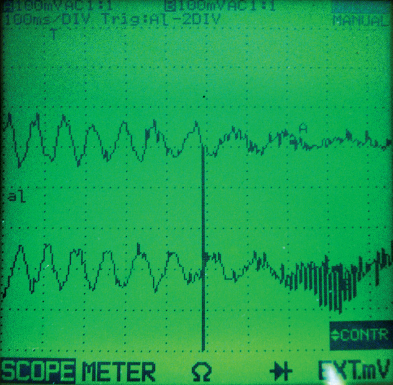
Computer control of vehicle dynamics necessarily requires sensors. In vehicles that incorporate ABS, ASR, and ESC, the speed at which each wheel is traveling is vital data that comes from four wheel speed sensors reading hub rotations. Volkswagen uses AC pulse generators for this purpose. These consist of a permanent magnet with a coil winding wrapped around it. As a toothed wheel attached to the hub rotates by the AC pulse generator it induces voltage in the windings. This is an AC pulse wave, similar to a sine wave. The voltage travels in both direction with half of the signal being positive and the other half being negative (below ground). This type of pattern can be measured by a Digital Multi-Meter (DMM) or an oscilloscope. With a DMM , you will only see a digital display of the peak signal voltage, whereas with a scope you can watch the pattern over time and see when the toothed wheel passes by the sensor and then the following air gap.
The 2004 Jetta was the first to use active speed sensors, which are on all current models, and work slightly differently from conventional pulse generators. Similar to Hall-effect sensors they receive a reference voltage from the ESC control unit, which powers an active Hall-type element. Instead of a tone wheel or toothed ring, the rotating hub contains a magnetic ring with alternating poles attached. As the poles pass by the Hall-effect element, they cause it to switch on and off. This alternately grounds and un-grounds the reference voltage and generates a square-wave signal. This signal does not necessarily have to go all the way to ground as most of us are accustomed to seeing, so do not expect to see a traditional square wave on your scope. The deflection between reference high and reference low can be very small and only a high-resolution scope can capture it. Luckily, with a VAS 5052 or equivalent you can monitor the data supplied by the self-diagnostic functions of the ABS, ASR, and ESC control unit.
Testing, Testing, Testing
There are a few ways to test the proper operation of a wheel speed sensor. Remember, it is made up of a coil winding with a beginning and an end. Since it is a continuous coil, you can measure the winding resistance between the two terminals. These specifications can be found in the diagnostic trouble code charts. With a paid subscription to
www.vw.erwin.com, you can look up these readings for the particular vehicle you are working on. If the resistance of the coils matches specifications, you can move on to the next test of measuring the AC voltage the sensor is generating. Since AC voltage is induced by the moving ring gear on the hub, you are going to have to spin the wheel to generate the signal. You should compare the signal voltage from one side of the axle to that of the other and make sure they are nearly identical. If both readings are close, you may have to scope the signals, particularly if there is no DTC for the sensor. Your customer may experience low-speed ABS activation even through the wheels are not locking up. This is because the ABS,ASR, or ESC control units is being fooled into believing that one of the wheels is traveling at a slower rate of speed than the others when it’s really not.
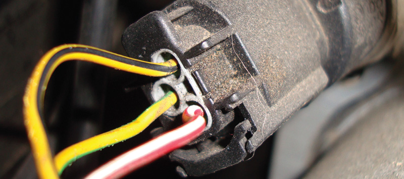
There are many more inputs the ESC control unit uses to maintain control of the vehicle, such as that from the brake switch. This tells the computer that the brakes are applied for a possible ABS condition, or that the brakes are not applied so that ASR and ESC may have to follow acceleration programs. In the past, it was always difficult for engineers to determine the driver’s intentions when both the brake pedal and accelerator pedals were applied at the same time. To help prevent pedal misapplication, the engineers came up with a brake fluid pressure sensor that determines if the brake pedal is really being applied to stop the vehicle, or if the driver is just resting a foot on the pedal. This is a three-wire sensor with a 5V reference, signal wire, and ground. As fluid pressure increases, the signal voltage goes up with it. Early on, this sensor was mounted on the ABS/ASR solenoid body, but in current versions it is inside the ABS hydraulic control unit, and cannot be serviced separately.
Feeling the Pressure
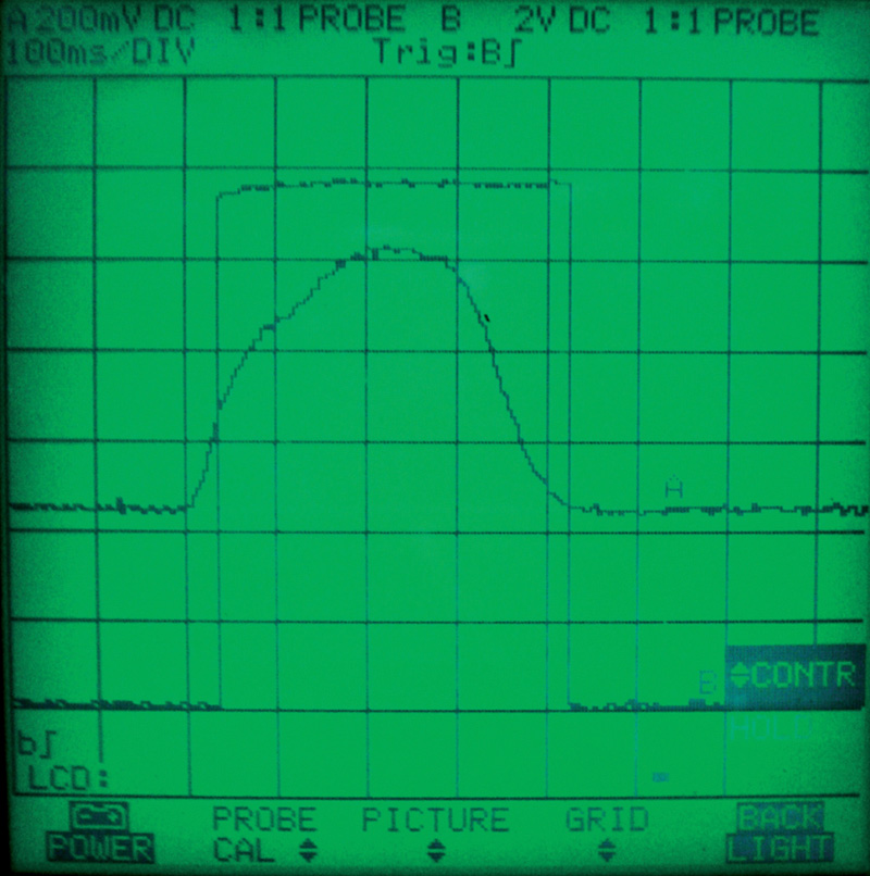
With the brake pedal at rest, you should see about 0.6V. If you apply the brake without the engine running, the signal voltage should go as high as 3.5V. It can go even higher with the engine running under hard braking. The ESC control unit cross-checks the brake fluid pressure switch with the brake switch. When the brake pedal switch changes states, the brake pressure switch needs to read below 1.0V, or you will set a code for the brake pressure sensor.
Traditionally, brake inputs override throttle pedal inputs for safety reasons. Between the brake pedal switch and the brake fluid pressure sensor, the ESC control unit can tell how quickly the driver wants to stop. If we only drove in straight lines, this would not be a problem, but during many driving situations the vehicle is being turned while braking and evasive maneuvers can cause a loss of control. More vehicle inputs are required to inform the ESC what direction the vehicle is being steered in and what the body pitch and roll angles are.
A steering-angle sensor lets the ESC control unit know how severe the steering angle is relative to vehicle speed. The sensor is usually mounted in the steering column and incorporated into the clock-spring for the driver’s side air bag, but the 2009 and newer Jetta and Golf, and 2012 and newer Passat with electromechanical power steering have this sensor in the steering rack. You cannot directly measure the signal voltages produced by it because it has its own processor and modifies the two steering angle sensor signal voltages into CAN communications the ESC unit can understand. You can read this information in the data of the ABS, ASR, and ESC control unit found in address #03. Here, you will read the signal as steering angle deflection off of center. This means that at some point the sensor will need to be centered. Enter “Basic Settings” and select basic setting block XXX. On later models, this may involve a road test with the driver alternating between left and right turns until the steering angle is learned.
Pitch and Roll
The ESC control unit now knows how the vehicle is being steered, but it also needs to know in what direction the body of the car is traveling. Is there a severe pitch forward from hard braking and body roll from hard cornering? For this on most earlier models, the ESC control unit used a combined sensor for transverse acceleration (usually G200) and a sender for rotation rate (usually G202). Each sensor has its own job. The transverse acceleration sensor measures forces in a straight line, forward and backwards. The sender for rotation rate indicates if the vehicle is being turned to the left or to the right. They are both three-wire sensors that share the same 5V reference and ground, but have two individual signal wires to send their two different signals to the ESC. On a level surface, the signal voltages stay static at approximately 2.5V. As you drive the vehicle, the reading will change according to direction. The signal voltage will increase in one direction and decrease in the other. The same applies to the sender for rotation rate. As you turn the vehicle to the right the voltage will change in one direction. Let’s say for example that the voltage rises to 3.0V; when you then turn the vehicle to the left, the voltage should drop from 2.5V. The more severe the change of direction, the greater the voltage change.
Much like the G201 brake pressure sensor, these are no longer stand alone components and cannot be tested with an oscilloscope or volt meter. The MK60 system has the sensors integrated into the ABS module. Even on some older vehicles (the 2004 Golf with ESC, for example), the G200 and G202 were part of the G419 ESC sensor unit, which still could not be tested separately.
When opening up the brake system for service, certain procedures will have to be followed. Depending on the vehicle you are working on, you may need to use your scan tool to bleed the brakes. For example, the New Beetle’s Teves system does not require a VAS 5052 to perform a brake bleed, but vehicles with the Bosch 5.7 system or ESC it is necessary to have roughly 30 psi of fluid pressure to properly bleed the hydraulic pump. This must be done first before the rest of the system can be bled. You will need to login to the control unit first. Then, select “basic setting” and enter block number 00. This will cause the ESC control unit to activate the hydraulic pump for approximately 10 seconds. The left front bleeder valve should be open at this point to let the air to escape. From here, you should continue to bleed each wheel individually, but not in the traditional sequence. You can get the proper bleeding pattern to show up on your VAS 5052 by using the GFF test plan. The goal, of course, is to make sure all of the air has been purged from the hydraulic system.
Finally…
Having a basic understanding of the components and how they come together to form the system is the first step in properly diagnosing your customers’ concerns. With your continuing education and your relationship with your Volkswagen dealer’s OEM parts network, you will be able to provide the quality of service that will keep your customers coming back and leaving happy. Good job, everyone.
Download PDF


0 Comments