
We’ll cover the highlights of crankshaft design and then we’ll discuss all the things you need to check before you load it in the block for the first time.
by Greg McCongia
The crankshaft is a major piece of your performance puzzle. It converts reciprocating motion to rotary motion, absorbs the shock of combustion, accelerates and decelerates the reciprocating components, delivers the oil to the connecting rod bearings, resists twist and deflection, mounts the drives for the cam, transmission, damper and front-of-engine mounted systems like the vacuum pump, water pump, power steering pump, alternator and dry sump pump. It has to spin, plunge, accelerate and decelerate, twist and untwist hundreds of times a minute, depending on its application. We’ll cover the highlights of crankshaft design and then we’ll discuss all the things you need to check before you load it in the block for the first time. It’s not my intention to cover the minutiae of crankshaft construction in these pages as there is an abundance of material on the Internet on both the crank suppliers tech pages and elsewhere… but we will make a high level pass and cover the basics so you know where to begin your own continuing education process.
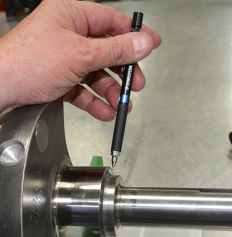
 Never assume that the parts are good. New parts means DIFFERENT parts, not good parts. If you read the text you understand how many things can go wrong in the manufacturing process. Never assume. Always check. The snout on this Ford crankshaft is a mile long and checking it for run out is a good first step. It won’t take much run out over this length to make a lot of movement at the end… in this case we were under a thousandth of an inch. |
 The crank is mounted in V blocks, sitting on a piece of flattened half inch aluminum plate. I’ve drilled and tapped a few holes to mount a post for my dial indicator and I’m reading the center main. Obviously this is not the only way to do this. You can also put the number one and number five main bearing in the block and spin the crank in the block. In this case the block wasn’t clean so I did it on the bench. |
Like every racing component, the engines power output and application dictates or limits your choice of product. Product choices are determined by targeted power outputs, cost, class rules on displacement or in some cases by other rules such as a “claimer” rule where putting an expensive crankshaft in an engine that another racer can claim just doesn’t make sense.
Crankshafts come in a multitude of types. Materials range from cast iron, nodular iron and cast steel to forged steel and billet. A casting is simply a hot pour into a mold in the shape of the crankshaft, whereas a forging is done by hammering or upsetting a hot blank into the desired shape. Forging takes many forms including drop forging, open die drop forging, press forging, upset forging and roll forging to name only a few of dozen or so available forging processes. Casting quality is dependent on the mix prior to the pour, the quality of the mold and the pour process itself, which has to be carefully controlled to avoid inclusions or voids. Forging is always done hot for crankshafts while the metal is more plastic and able to flow. Forging straightens and compacts the grain, thereby increasing strength.
 “You don’t know what you don’t know”. Until you check it. You can see it’s all zeros all across the indicator with the V blocks on the mains and the indicator stem on the crankpin. Don’t be surprised to find .002-.006” variation on a crankshaft that costs less than $1000.00. I can tell you this; a $3,000 crankshaft will be exactly the same from crankpin to crankpin. This rule is universally true… the more you spend the better the tolerance. It’s not that affordable parts won’t do the job, in many cases they will do just fine. Just understand the application and choose the parts based on the intended use. |
 Just a couple of ten-thousandths short of a perfect 4.250 stroke. This crank was off from end to end by about .005” on the stroke check… not a deal breaker. You can check stroke in the block as well, but you have to measure all the rod lengths and all the compression heights on all the pistons and run the math to get there but it still won’t be as fast or as accurate as using this tool. |

Above: There is nothing worse than putting everything together and finding out that the pilot for the torque converter won’t fit the crankshaft counter bore. Unless it’s finding out that the converter is right and the crank is made wrong! While you’re here make sure you grab the flywheel or flex plate and verify the bolt pattern in the rear flange and if you are reusing the flywheel or flex plate check the ring gear teeth.

If you don’t own a set of radius gages now is the time to get them on that Christmas list. There should not be a sharp edge anywhere down the length of the crankshaft. Sharp edges are stress risers start and stress risers cause explosive and catastrophic failures. Unless you have a burning desire to have your car featured somewhere on YouTube as “the worst engine fail ever” these should be avoided.
Most stock crankshafts are cast iron, but a few specialty stock applications are either forged steel or nodular cast iron. While most varieties of cast iron are brittle and fracture prone, nodular or ductile iron has much better impact and fatigue resistance due to its nodular graphite inclusions. Since even the best cast cranks tend to be far more brittle than a forging their use in high performance applications is generally limited to outputs of up to 500 horsepower, although some aftermarket manufacturers out there are now claiming that their cast cranks exceed 100,000 PSI tensile strength and 6% elongation and as such can handle more power. A few professional engine builders have stated that they’ve used those crankshafts in applications exceeding 700 horsepower without reliability issues. Personally, I always use a forging. A decent forging is usually only $300-400 more than a premium cast crank and if your money is so tight that you can’t afford a forging you need to find a different hobby!

Measure the keyway groove and the key. A mild press fit of 1/1000th of an inch is fine. You should be able to start every key into the groove. If you’re running a crankshaft with multiple grooves like you would for blower applications, make sure you measure and record the width of every groove.

This little drawing on my “rolling Post-It note” shows you what to look for. Clockwise from the upper right, the size of the journal, measure at twelve to six and three to nine at two spots on each journal just inside of the radius. Also check for apple coring, barreled or tapered journals.
When an engineer discusses materials and application you may hear them refer to compressive or compression forces, pushing things together or forces in tension, those things that are pulling pulled apart. For example, the outside walls of a building exert a compressive force on the foundation of the building but the cables of a suspension bridge are being pulled by the weight of the bridge below. The tensile strength of a material is the amount of pull in pounds per square inch required to pull a one inch round bar apart, and the elongation percentage is a measurement of how much the cross sectional diameter narrowed before the material pulled in two at the measured tensile strength. For our cast iron example a one inch bar of the cast material pulled in two at 100,000 PSI and the diameter of the bar was reduced by 6% through the break. A low elongation percentage is an indicator of brittleness and a higher percentage is an indicator of ductility. Elongation numbers are most important when studying brittle fracture.

Measure the snout of the crankshaft so you can have your aftermarket damper honed to fit. Most dampers will have a specification for press, usually only about 9/10,000 of an inch. In my experience nearly all arrive with far too much press and the damper has to be honed. Too much press will only break your installation tools and make you cuss… and just wait until you try to get it off for maintenance!
Forged steel crankshafts come twisted and non-twisted although most forged cranks on the market today are non-twisted. Twisted cranks are forged in a single plane, flat configuration with all of the crank pins in either the six or twelve o’clock position. The still-hot crankshaft is then placed in a fixture and two crankpins are twisted into final location at the three and nine o’clock position. You get the advantage of the improved grain structure of the forging process but at the same time you get some added stresses through the twisted areas. Non-twist forgings are forged in two planes with the crankpins in place at twelve, three, six and nine o’clock (for a standard V-8 engine.) Non-twist forgings are more money because the two plane forging process requires more expensive and less durable tooling and because the process generates more waste. Tensile strength for typical steel forgings runs between 115,000 and 145,000 PSI with elongation percentages in the 22-25% range.

If you have spacers, sprockets or belt drive systems always check to make sure that they will fit the snout before you try to mount them permanently. In this picture I’m using the old parts to verify that the new crank dimensions were the same as the OE crankshaft. The new spacer and ATI damper are on the way.
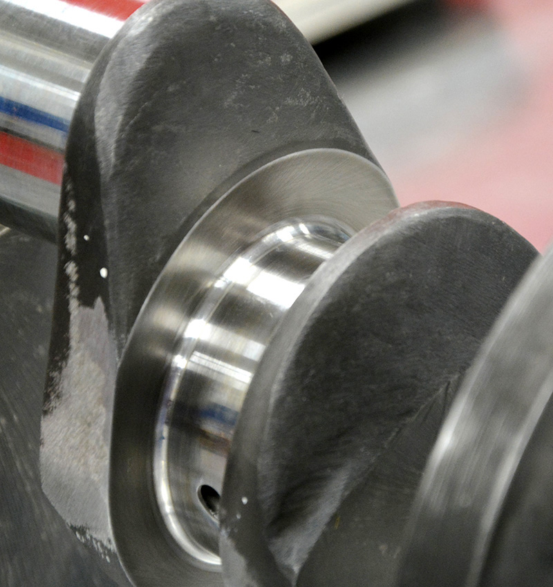
 This is a good example of the kind of machining you’re likely to see on a performance crankshaft. No sharp edges! |
 Check the deflector at the rear main seal and the transition from the rear main to the rear flange for sharp edges. Leave no horizontal to vertical transition point uninspected. |
The thrust surface should be a smooth as the bearing journal. Even a slight amount of surface roughness will destroy the rear thrust face. There can be tremendous pressure applied to the rear thrust surface by the torque converter or by a high pressure clutch pressure place. I know, we’re supposed to check the converter depth of engagement and make sure that you have to pull the converter forward to meet the flexplate but it’s possible for the converter to friction lock in the front pump gear under heavy throttle conditions. There is no direct oil feed to the thrust bearing, so accelerated wear is a real possibility. When you install the crankshaft measure the end play with just the upper bearing in place and once again with the cap installed. The end play should not change. If it does you may need to adjust the cap fore or aft to align the thrust surfaces.
Billet crankshafts are fully machined from a piece of (typically) hot rolled or roll forged square or round stock. The advantage of a billet crankshaft is that it’s a relatively affordable way to make a special, low production crankshaft, with the added advantage that the material can be specified by application and the grain structure can tightly controlled and made uniform. The rough is mounted in a lathe and the crankshaft is then fully machined from that single piece of high quality steel… basically they machine away all the parts that aren’t a crankshaft. Typical tensile strengths of a billet run between 140,000 PSI and 165,000 PSI with elongation percentages in the 22-25% range.
Once the manufacturing process is complete crankshafts undergo a series of processes including heat treatment, polishing and surface preparation and heat, cryogenic or vibratory techniques to provide stress relieve, harden the journals, normalize, anneal or temper them. Precisely which process is used depends on which manufacturing process is used and which material the crankshaft is made of. Cast, forged and billet cranks all have different requirements just due to the manufacturing methods and not every heat treating process works for every type of steel or iron and because some processes are performed at lower temperatures than others because parts that are subject to distortion at high temperature may be better treated by processes using lower temperatures.

Never use a tap, always use a thread chaser and always run every bolt hole, every bolt and every nut. A tap and die is designed to cut threads and should never be used to chase existing holes unless you have no other choice. I’ve found a lot of poorly formed threads on brand new parts and it’s better to find it now than when it’s bolted up in the chassis.

This is what a properly polished crankshaft should look like. This measures less than 1 RMS. Journals this smooth are easy on bearings, even under extreme load. There are several ways to measure surface finish, including several non-contact methods that have been developed in recent years.

Most crankshafts have several steps ground in check every step, every transition for smooth, polished radii. Part of my process is I use a magnifying visor during my inspection to see all those little things that my ancient eyes no longer see without assistance. Now is a good time to check oil feed hole chamfer and feel for any rough areas. Conservative chamfers work best, those big wide chamfers just leak oil. You can normally detect about one or two thousandths variation with just your hands. Didn’t know you were that well calibrated, did you?

I run a piece of solder or aluminum TIG rod through every oil hole. Every oil feed hole must be clean and fully drilled and the oil hole timing must be correct. Most oil holes time up just as compression starts to build, about when the crankpin is coming up to the 8 o’clock position. Check both ends, at the rod and at the main, unless you’re running a fully grooved main bearing. The main feed hole to the rod bearing needs to be lined up with the oil source, or upper main bearing supply. Cross drilling is no longer a recommended process particularly if your application spins over 6800 RPM or so. At some point over 7000 RPM the oil can actually centrifuge out of the crankshaft and starve the rod bearings of oil.

Using my poor man’s surface plate again, this time to check the flange face runout. It’s not a bad idea to check the thrust faces for run out as well.

Verify the pilot inside and outside diameter runout.
If you are interested in learning more about metallurgy and the manufacturing process a simple Internet search will yield hundreds of sites where you can go and learn far more about the topic than normal people would consider sane. Composition, forging methods, working heat ranges and surface treatment processes are covered at length.
All crankshafts must undergo some final machining process to make them commercially viable. Radii must be machined or rolled in, counterweights trimmed; oil holes drilled, bolt holes must be drilled and tapped, the stroke must be ground-in and the bearing surfaces finely polished. Throughout the process there are a lot of ways for errors to be introduced into the product. The more complicated something is, the more steps in the manufacturing process the greater the possibility that an error is introduced into the process… which is why we’re going to take a quick look at all the real-world things you should check before you even get the crankshaft near the block.
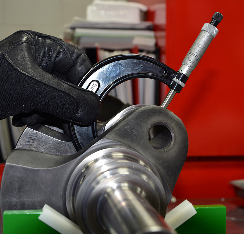
If you’re using 1/10,000 inch-reading micrometers you’ll need to keep the heat of your hands from affecting the readings. Just a little heat from your hands will change the reading by as much as a half thousandth. While that might not sound like a lot you are often setting your oil clearance in a half thousandth range. Measure each journal in four spots, two on each end of the journal 90 degrees apart around the circumference of the journal.
I’ve included a few links that you might find helpful. Most manufacturers have tech notes or technical information available for free on their websites, a very valuable source for the beginning (or expert!) engine builder. This list is by no means comprehensive and I apologize to those I may have inadvertently overlooked.
https://www.crower.com/
https://www.scatcrankshafts.com/
https://www.winbergcrankshafts.com/
https://www.eaglerod.com/
https://www.lunatipower.com/
https://bryantracing.com/
https://www.molnartechnologies.com/
https://www.remchem.com/http://www.micropolishing.com/home/

0 Comments