
The CAN (Controller Area Network) concept has made our lives easier by connecting all the computers in the car in a network we can access with a scan tool. But what do we do when you cannot communicate with one or several of those computers? Believe it or not, it’s not that hard!
If you’re just getting into the business of automotive repairs, everything probably seems normal to you. You don’t remember when an ignition system had a pick-up and a module. You don’t remember when fuel injection used the triggering of the ignition coil to tell the computer when to trigger the injectors. You probably don’t even remember when there was only one computer in a car! Those of us who’ve been around this business for a couple of decades or more, on the other hand, have seen an evolution of modern electronics that might better be called a revolution.
Computers are everywhere now. It seems that just about every system on a modern car has some sort of electronic control. Power windows have convenience and safety features that are computer-controlled. Power seats have memory functions that require input requests, position sensors, and output drivers that supply power/ground to the motors. Multimedia is now all computer-controlled. While each system on the car has some sort of electronic logic controlling it, each has different needs.
What’s the frequency?
Body control systems do not need super-high-speed data transfer, but music and video does require a lot of data to be moved from place to place. Drivetrain systems are different. When a vehicle starts to lose traction in a corner, it is critical that the wheel speed of that tire is picked up by the ABS/Traction control module. The control unit will apply the brakes or the traction control system may request the PCM (Powertrain Control Module) to reduce power output by retarding ignition timing, limiting injection pulses, and closing the electronic throttle until the wayward tire regains its grip on the road. This needs to happen as quickly as possible, so powertrain systems operate at a higher baud rate than, say, body control functions.
Certain features require information from these different systems. For example, look at the power door locks. Technicians have the ability to program a control unit to lock the doors automatically when the vehicle reaches a specific speed. How does the body control unit know how fast the car is going? Does it have a speed sensor to provide that information? Some multimedia systems can increase the volume as road speed (and road noise) increases. Does the radio have a speed sensor also? That would mean three separate speed sensors would be needed, one for each system. These redundancies would increase the number of wires and the complexity of the system. In an engineering effort to streamline and simplify wiring, all of these different systems share information. Since the ABS/Traction Control system reads the wheel speeds directly, it shares this information with the rest of the car. The body control module can use this information to determine when the power door locks should be locked, and so on.
Lines of communication
As we mentioned earlier, the powertrain management system operates at a very high baud rate to be able to react quickly and keep the car under control. The body control system does not have to react as quickly to a request to open a window or adjust a seat. Two different systems operating at two different baud rates are like two people speaking two different languages. They are not going to understand one another. There has to be an interpreter. When computer systems operate with different software languages, they also need to have an interpreter, which is referred to as a “gateway.” The job of the gateway is to translate the information from one computer system into the language to the other system(s) can understand. How are we going to communicate with all those systems on Volkswagen vehicles? A VAG5052 factory scan tool is the best answer.
The job of a scan tool is to communicate with the vehicle on a software level. Software built into the computers or each system monitors the data coming in and going out. The scan tool can interpret this information and display this data. If the software in the computer detects a malfunction in the system, it will register a diagnostic trouble code (DTC). A technician can retrieve this DTC and use it as a starting point in diagnosing the problem. Once the repair is made, the DTC can be cleared and the car can be released to the owner. On more sophisticated systems, the scan tool can send commands to the car’s computers and request that outputs be turned on. As technicians, we can use electrical test equipment to measure the computer’s ability to supply power or ground to computer-controlled outputs, but with all the different computer systems on today’s vehicles, computerized diagnostics are a big help.
Complexity or technology?

Imagine trying to diagnose a problem using only your Digital Multi-Meter (DMM). This involves removing panels to access electrical connectors, tapping into the system with your DMM while activating each output until you identify the one that’s malfunctioning. It sounds very time-consuming because it is. Using self-diagnostics and isolating the problem first by looking at the DTC speeds things up. You can then perform specific electrical tests on the malfunctioning system the self-diagnostics have identified as a problem. Younger technicians probably don’t remember when you had to check inputs and outputs manually. The first move everyone makes today is to reach for the scan tool, which is not a bad idea in this day and age (after you’ve done an over-all visual inspection, that is). Can you imagine your frustration with having complex diagnostic problems and not having a clue about what’s going on?
But what if you have a problem with a car and you cannot communicate with the system even with your scan tool? How should you approach this challenge? We are lucky to be working on Volkswagen vehicles. Their CAN is referred to as a “robust” system. This means most of the data from each computer system is put out on the bus. It is the job of the control unit receiving the information to detect the information that is important to them and retrieve that specific data. With all the information on the CAN bus, each individual control unit only monitors the data on the bus that it needs. It also sends its own information out on the bus. If an individual computer has lost power due to a blown fuse, or simply malfunctions, then it will not retrieve the information that it needs and it will not broadcast the information it has detected from its own sensors. The other control units could then detect the missing information and set a DTC indicating which control unit is not sharing its information.
Opening up the lines
This means if a control unit were to fail it, would probably not interfere with other control units communicating on the CAN. Diagnosing a problem of no communication sounds like a daunting task for an auto technician, but it is simpler than you might think. If you have a VAG 5052, you can scan all of the control units using the auto scan feature. Each control that cannot find information will flag a DTC indicating that information from a specific control unit is not received. If several control units do not receive information from one specific control unit, you need to find that control unit and verify the failure with electrical testing. The first step is to verify the control unit is getting the power supply it needs. This is often through a fuse, so look at the wiring diagram to find out which fuses you need to check. Since control units are on the expensive side, you’ll want to verify at the control unit that the power supply and the grounds are present.
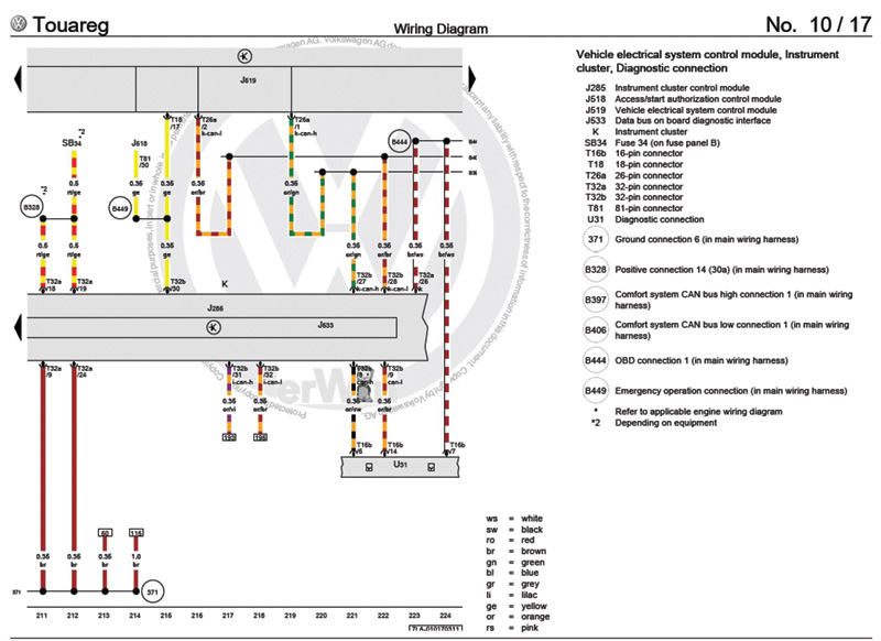
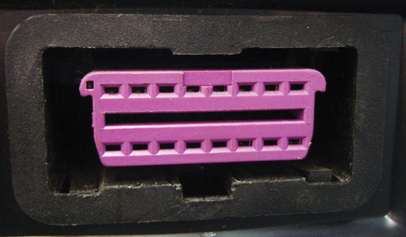
For this, you need access to the control unit and the pin locations of the voltage supplies, grounds, and the computer data lines. Most of the time, you can start by scoping the data line wires at the OBD II connectors. Look at the wiring diagram for the OBD II connector on the 2006 Touareg we are using as our example and you’ll see that pin #2 goes to the ABS traction control unit, probably for programming. The scan tool sends communication requests through pin #7 to the instrument cluster module, which is the gateway. This module acts as the go-between of the vehicle and the scan tool connection. It has one request wire and two CAN communication wires that go off to the diagnostic connector. These wires will have no communication signals unless a request is made from the scan tool through pin #7 (the request wire). Then, the module connects the two wires going to the OBD II connector to another two wires that connect to the CAN system on the vehicle.
How it actually works
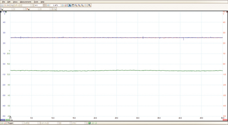
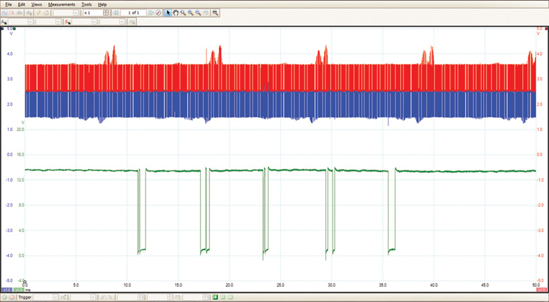
Another way of looking at it is the instrument cluster is all the OBD II really connects to. Pin #7 of the OBD II connector carries the scan tool request, and pins #6 and #14 carry the CAN signals from the cluster to the scan tool. The instrument cluster is always connected and communicating with the car from a different pair of CAN wires on the cluster. Those are always communicating when the key is inserted into the ignition switch. If you were to scope pins #7, #6, and #14, you would see only straight voltage on each wire. Pin #7 would have battery voltage, and pins #6 and #14 would have 2.5V. As you request communication with your scan tool, you would see an intermittent wave form pattern on pin #7 from battery voltage to almost ground with your scan tool set to about 5ms time divisions. This is the scan tool request to the instrument cluster to start communicating.
The module would respond by opening up the lines of communication on pins #6 and #14 and you would see a very fast square wave on each. To see a clear pattern, you will have to set the scope to 50 µs. This is not necessary to determine if the communication lines are open. For the CAN high signal, you will see the voltage square wave signal bounce up between 2.5 and 3.5V. The CAN low signal will also oscillate between 3.5 and 4.5V, and the two patterns will mirror each other. This same signal will come out of two different pins on the instrument cluster and communicate with the CAN system. For the entertainment systems, there is an additional CAN from the cluster to components such as the wiper module, radio, amplifier, telephone, etc. This is a separate CAN that is mainly for multimedia and entertainment components.
Basics
If the CAN system wires do not have a square wave, then you either have a problem gateway, which is our case in the instrument cluster, or the CAN wires are physically shorted to power or ground. You will have to find the source of the problem by testing and inspecting the CAN wires directly. Knowing how the scan tool communicates with the car and what to do when it doesn’t will help speed up your diagnosis. By the car giving you the information you need, you will also have a more accurate assessment of the problem and repair. Once you have determined that there is scan tool communication, you can start looking at the problem computer. This knowledge and a relationship with your Volkswagen parts department will allow you to make more complete and accurate repairs, and who wouldn’t want that?
Download PDF


0 Comments