

The regenerative braking systems on Nissan hybrid vehicles can be confusing and misunderstood. Let’s take a look at how these systems really work.
If you’ve been working in this field for a while, you probably remember being surprised when you pulled the wheels off your first hybrid. Where were the “regenerative brakes?” There was nothing behind the wheel but the familiar disc brake setup, just like a regular car. How does the car capture braking energy using regular brakes?
As I’m sure you know now, the braking is split between the “regular” brakes and a motor/generator, attached to the wheels through the axles. This article will focus on how this division of work is accomplished. We’ll explore the components that make up the system, their responsibilities, and how the whole system works together to seamlessly provide the braking the driver wants while capturing the energy normally wasted.
Modern braking systems are complex, but possible to understand in bite size chunks. This article will avoid discussion of ABS, VDC, collision avoidance, and other features that add complexity and might delay understanding of how regen works. Also, systems vary, so this article will not match every Nissan hybrid. However, systems will be similar and what you learn here will speed understanding when encountering new models like the 2014 Pathfinder hybrid.
Making a New System Undetectable from the Driver’s Seat

These Master Cylinder Pressure sensors are the primary input for driver braking request.
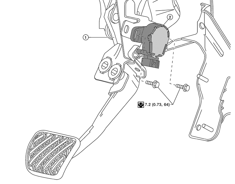
Let’s start with the most important thing about the system: “what the driver wants.” Brakes are there to slow or stop the car when the driver wants. Everything else is less important. So, how does the driver communicate his or her needs? The braking request could have been designed around almost any input device, but Nissan wisely chose not to “reinvent the wheel” and stuck with the familiar brake pedal. If you know how to drive a car, you know how to drive a Nissan hybrid. Not only is the input method the same, the “feel” of the brake pedal is the same as any other car.
The perception of the braking experience may be the same, but what’s happening behind the pedal is very different. The brake pedal is linked to a master cylinder via a push rod. Familiar enough, but then things get different.
The fluid pushed from the master cylinder creates pressure in a “dead end” in the brake actuator where two pressure transducers measure how hard the driver is stepping on the brake pedal. The Master Cylinder Pressure sensors are the primary input for driver braking request. Because the master cylinder is pushing fluid into a “dead end,” the brake pedal would have no give and feel weird to the driver, so a spring-loaded piston is used to simulate the flex of calipers and brake hoses. This gives the driver a “regular” feeling brake pedal.
An added benefit to using a real brake master cylinder is that in the event of a system failure, it can be used to apply the brakes, just like a regular car. Two normally-open solenoid valves connect the master cylinder output lines to the calipers. The solenoid valves only close when the system is operational. When closed, the master cylinder pushes fluid into the pressure sensors for the driver braking request input, but if something goes wrong or the vehicle is simply not powered up, the fluid goes to the calipers and the car brakes normally.

In the event of a system failure, the failsafe solenoids will close and direct brake fluid to the calipers to stop the vehicle.
After thinking about the failsafe operation, you might be wondering if the stroke simulator makes the brake pedal feel mushy when the failsafe valves are open. After all, the driver would feel the flex of the lines and calipers on as well as the calibrated mushiness of the stroke simulator, right? The engineers thought of that too, and there is an additional solenoid that prevents the stroke simulator from functioning. If a problem develops, or the vehicle is not READY, the Stroke Simulator Control Solenoid prevents stroke simulator operation and helps maintain a firm pedal in failsafe mode.
In addition to the pressure sensors that monitor master cylinder output, a stroke sensor is also used on some systems. The stroke sensor is a redundant sensor with dual variable voltage outputs similar to a throttle and accelerator position sensors. The stroke sensor allows for fine tuning of brake response to driver input.
Making the Driver’s Request Happen
 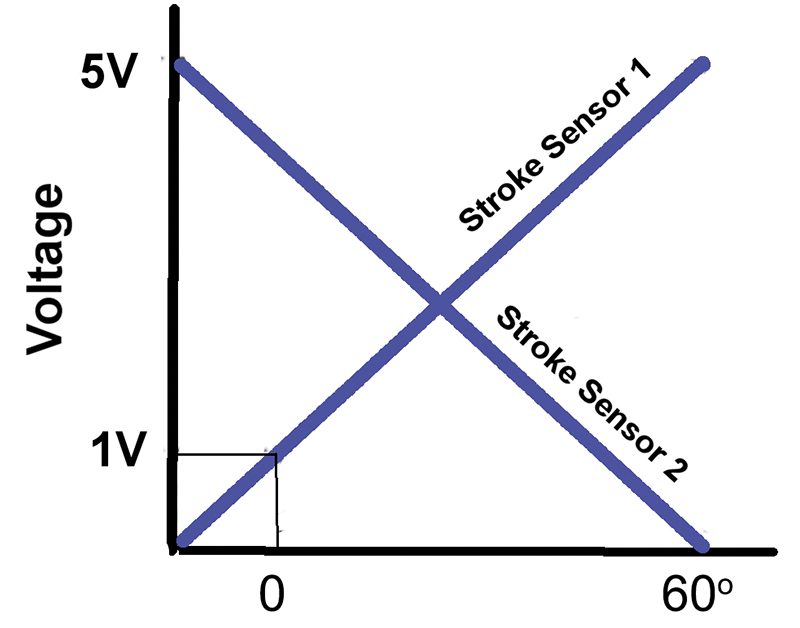 |
| The stroke sensor found on some systems has a dual voltage output. |
The primary control for the brake system is the ABS ECU. Ultimately it decides what percentage of the requested braking will be performed by the disc brakes, and what percentage will be provided by the electric motor/generator. However, it must first check with the hybrid control unit to find out how much torque the hybrid system can provide, and it must check with the actuator to get the master cylinder pressure sensor readings.
There are three major players involved in converting the driver’s braking request into a combination of regenerative braking and friction braking: the ABS control unit, the hybrid control unit, and the ABS actuator.
The primary control for the brake system is the ABS ECU. Ultimately, it decides what percentage of the requested braking will be performed by the front brakes, and what percentage will be provided by the electric motor/generator. However, it must first check with the hybrid control unit to find out how much torque the hybrid system can provide, and it must check with the actuator to get master cylinder pressure sensor readings.

The ABS control unit, the hybrid control unit, and the ABS actuator work together to decide the proportions of regenerative braking and friction braking.
There are several limits to regenerative braking. First, the motor/generator has a maximum torque output as a motor. This same torque limitation applies when it is being used as a generator. The generator can only develop so much negative torque, and if the braking request exceeds the maximum output of the motor/generator, the remainder will need to come from the conventional brakes. Another limitation is the battery. If the battery is fully charged, there is nowhere for any power generated to be used or stored, so regenerative braking cannot be used. Thus, the ABS ECU may issue a request or regenerative braking that cannot be met by the hybrid control unit so they are constantly negotiating back and forth.
The ABS actuator is a densely packed unit with a lot of different components and functions, so we’ll need to break this player into small sections to talk about it. First, let’s talk about brake fluid pressure. On a traditional brake system, the line pressure to apply the caliper comes from the brake master cylinder. There is often a brake booster to make the pedal easier for the driver to press, but the pressure is coming from the master cylinder pistons. As you’ll remember from the beginning of the article, the brake master cylinder output dead ends into a pressure sensor and does no work in this system; it is simply measured.
The pressure necessary to apply the brakes is generated by an ABS pump. This pump is driven by an electric motor that is powered by two relays. One relay supplies power to the pump through a resistor wired in series with the pump motor. This provides a low (quiet) speed. The other relay provides full power to the pump motor for a high (fast) speed. The pump can run slow and quiet, fast and louder, or shut off entirely. Having two speeds and two relays also provides redundancy. If one relay or circuit fails, the other can power the pump and maintain full brake function until the driver has a chance to have the warning light addressed.
The ABS pump can generate pressure pretty quickly but pressure will dip as the brakes are used and rise as the pump runs. Since the ABS actuator needs to precisely modulate caliper pressure to match driver request, it’s helpful to have a stable supply pressure. This is accomplished with an accumulator. This device is sort of like a capacitor for a hydraulic system. It stores pressurized fluid to even out dips and spikes in the pressure supply.
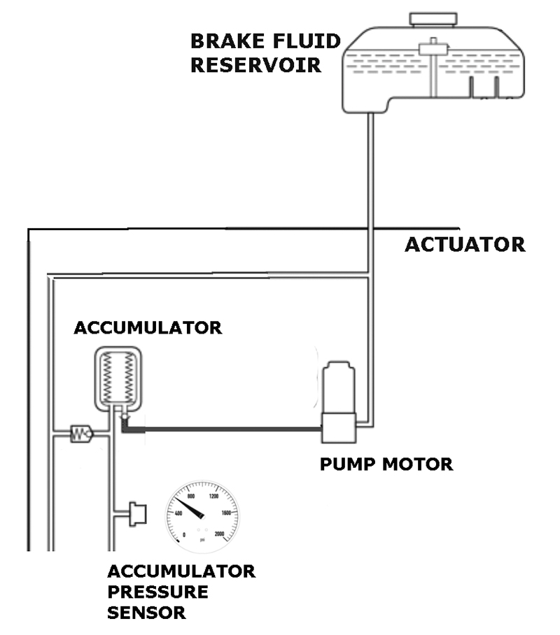
The accumulator stores pressurized fluid to even out dips and spikes in the pressure supply.
The accumulator is a fluid reservoir backed by a diaphragm and inert pressurized gas. The diaphragm presses against the fluid reservoir and maintains steady chamber volume and pressure as fluid is used and added to the reservoir. Thus, the accumulator prevents rapid pressure drop when the brakes are applied and buffers rapid pressure rise when the pump is running.
We now know how pressure is created and stored, but how does the ABS control unit know when to run the pump and when to shut it off? I suspect you just guessed that there is a pressure sensor in the accumulator, and you were correct. Take a look at the accumulator pressure PID with the CONSULT and furiously pump the brake pedal. You may be surprised at how steady the pressure remains. This system works really well.
So now we know how a steady supply of pressure is created to apply the brakes, but how is the pressure modulated to precisely match the driver’s braking request minus available regenerative braking? The four brake caliper pressures are controlled individually. This allows for all sorts of cool things to be done with ABS and VDC, but let’s ignore those systems for now.
Pressure comes from the accumulator. Pressure can be released into the brake fluid reservoir. Each brake line is connected to two solenoid valves inside the actuator. One valve connects to the accumulator, the other to the reservoir. When the accumulator valve opens, the line pressure increases. When the reservoir valve opens the line pressure decreases.

The pressure control system.
There are eight solenoid valves (two for each wheel) called linear valves. Linear can mean, “of or related to lines”, and these valves control the brake line pressure, so that definition sort of works and makes it easy to remember what they do. Or it can mean, “having an output that is directly proportional to the input” and that seems like a pretty good definition too as brake pedal input is proportional to the pressure of the linear valve output (if we forget about regen). However, the “real” definition here is the engineering definition of linear valve. A linear valve has a pintle shaped in a way that its flow rate is directly proportional to its lift. For example, if the valve is at 30% lift, the valve will flow 30% of its maximum flow rate. This type of valve makes fine and repeatable control of line pressure possible.
Now that we know how line pressure is manipulated, can we trust that linear valves are so precise right out of the box, that no calibration is needed? Nope. Just like O2 sensors were added to engine control to verify fuel maps were correct, the linear valves need a feedback loop and “long term fuel trim”, as it were, in order to ensure accurate pressure modulation. The pressure for each caliper is monitored with a pressure sensor inside the ABS actuator. The caliper pressure sensors are used calibrate the linear valves and the calibration information is stored in the ABS control unit. So if the actuator or the control unit is replaced, the calibration must be repeated. The calibration can also be “undone” with a CONSULT. This will cause a warning light and braking feel that is noticeably out of proportion with the brake pedal pressure.
Putting it all Together
Let’s review what we’ve learned and follow the action from the sole of the driver’s shoe to the tread of the tire. When the driver presses the brake pedal, the amount of pressure and pedal acceleration are measured by the ABS ECU to determine the braking request. The ABS ECU and the HV ECU negotiate so that the maximum amount of braking request can come from the motor/generator as regenerative braking. The ABS ECU provides the remainder of the braking by applying fluid pressure stored in the accumulator to the wheels by precisely metering the pressure to each wheel with linear valves and wheel cylinder pressure sensors working together in a feedback loop. The blending of regenerative braking and conventional braking is so seamless that it’s usually impossible for the driver to tell that there is any difference from a conventional car that wastes energy every time the brake pedal is pressed.


0 Comments