A little confused about how Nissan ignition systems function? Here’s the help you need.
From the dawn of production automobiles, switches were used to provide power to the ignition system and any other electric components. As stealing horses gave way to stealing cars, a lock was added to the ignition switch to prevent someone from driving off in your new car. This simple version of the locking ignition switch has been around for nearly a century now, but you may have noticed that it’s disappeared on many Nissan products.
Providing power to all the electrical systems is now a responsibility shared by a few different components: the IPDM (Intelligent Power Distribution Module), the BCM (Body Control Module), the ECM (Engine Control Module), the Fuse Block, and the Start Button or Ignition Switch. These components make up the PCS (Power Control System) and take over the traditional role of the ignition switch.
In this article, we’ll focus on the PCS (the switch), and ignore the immobilizer and I-Key systems (the lock). The information in this article will be based on the very popular Altima, but will be very similar to the systems found in other Nissan vehicles.
If it’s Not Broke, Why Fix it?
Why bother changing a component that’s worked for so long? There are several reasons:
- Less wiring; there’s no need to run as many thick wires and inputs can be shared via a network.
- Less current and heat in a single component making failure less likely.
- The ability to integrate the Intelligent Key System for passive entry and starting.
- Self-diagnostic capabilities make intermittent “switch” problems easier to diagnose.
- A battery saving feature to prevent the 12V battery from discharging.
- Current sensing and self-protection features to prevent damage from shorts, frozen electric motors, and other sources of over-current.
Meet the PCS Team Members
The Push-Button Ignition Switch or Keyed Ignition Switch
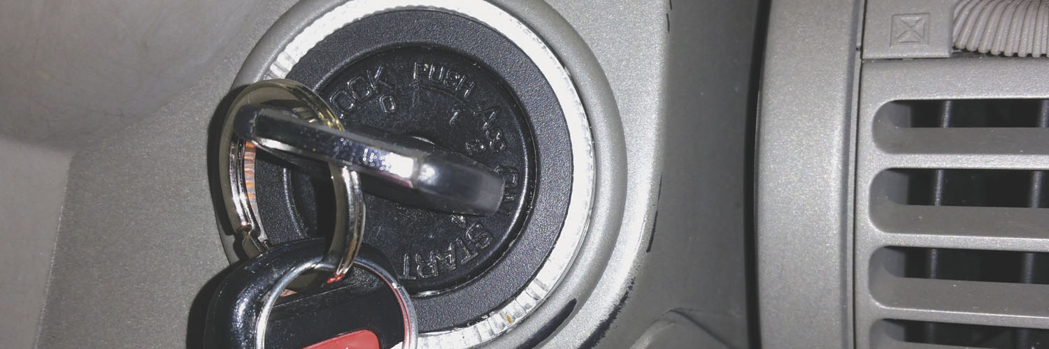
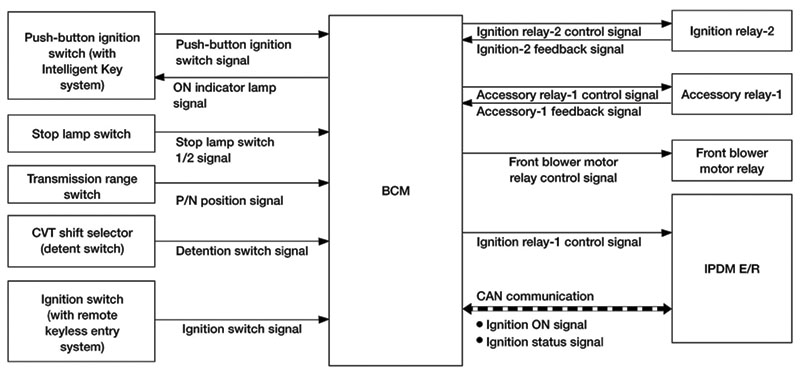
The Push-Button Ignition Switch or the keyed Ignition Switch perform the same function: both are inputs for the BCM, which relays their status to the IPDM via the CAN bus. Of course, a vehicle will only have a push button or a key, not both. On vehicles with a keyed ignition switch, the switch isn’t like a conventional ignition switch. It doesn’t carry any real current, it’s just a signal to the BCM. The push-button or keyed switch is also a BCM output. The BCM turns on LEDs in the button or on the switch bezel to indicate the current power mode: OFF, ACC, ON, or READY/RUNNING
The Accessory (ACC) Relay
The Accessory Relay provides power to the systems normally powered by the ignition switch while in the ACC position, such as the audio system, power windows, power ports, and the user interfaces for climate control and navigation. The Accessory Relay winding is powered by the BCM based on input from the ignition switch. If the control side of the relay circuit fails, a B2611 trouble code will set. If the switched side of the relay circuit fails, a B2614 will set. These trouble codes make diagnosis of intermittent problems a lot easier. The ACC relay can be removed and replaced independently if needed.
The IPDM – Intelligent Power Distribution Module
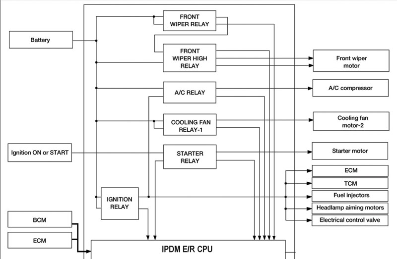
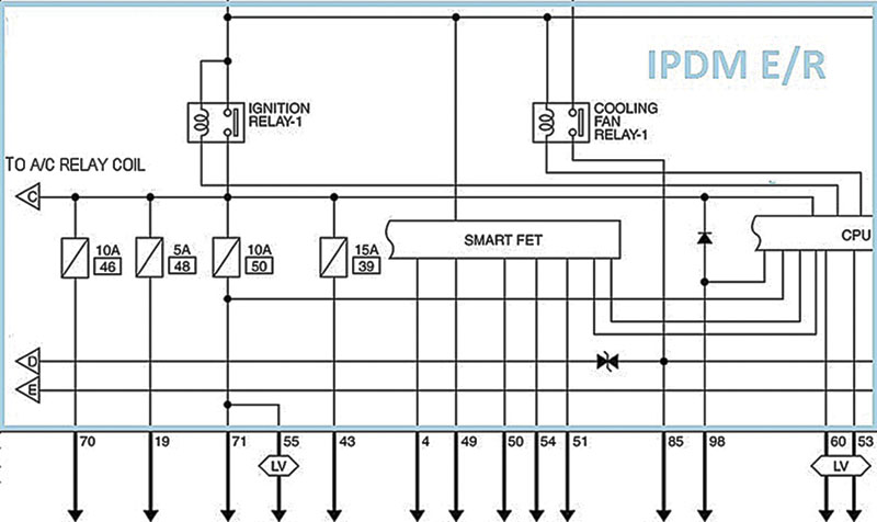
The IPDM is located in the engine compartment on the Altima and many other cars. In the manual, you’ll notice that it’s called the IPDM E/R. The “E/R” stands for Engine Room. The IPDM detects the ignition switch position (button or key) and sends that information to the BCM via CAN. Once the BCM receives the switch position information, it can request the IPDM close its internal Ignition Relay #1, which powers up several ECUs, the fuel injectors, and several lights.
The IPDM also houses several other relays for the wipers, cooling fans, and AC compressor. The relays in the IPDM cannot be removed from the IPDM, so don’t attempt to pull them for testing because it will damage the unit. If an IPDM relay fails, the unit must be replaced. Like the ACC Relay, each of the relays in the IPDM is monitored for faults and will set a trouble code if there is a failure.
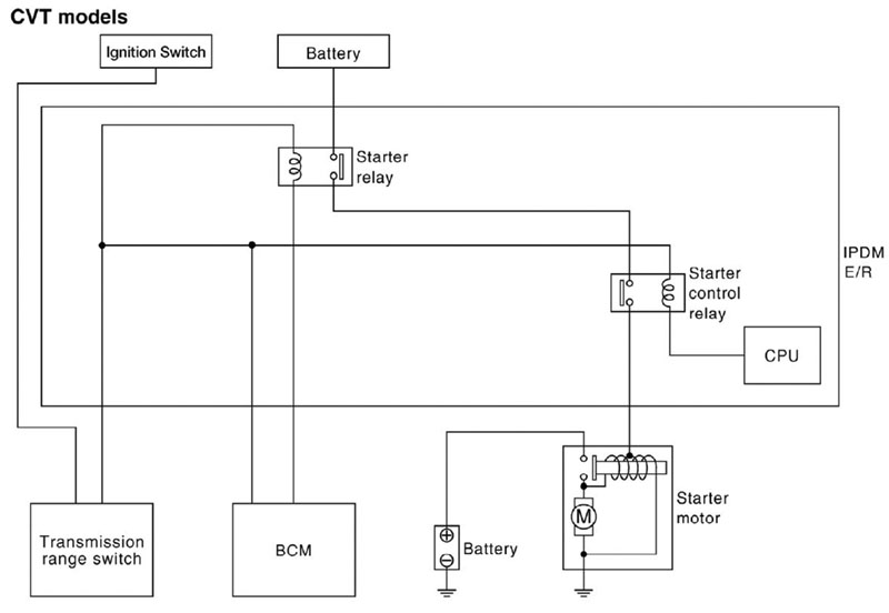
The IPDM also contains two relays for starting: the Starter Relay and the Starter Control Relay. The Starter Relay coil is grounded by the BCM, powered by the Transmission Range Switch or the Neutral Safety Switch. The Starter Control Relay coil is powered by the Starter Relay and grounded by the IPDM. You may have noticed that you don’t need to hold the key in the start position until the engine runs on newer cars. Once the key is turned to the start position, even briefly, the Starter Control Relay is held closed until the engine starts. If the engine cranks for an excessive period and the engine does not start, the relay will be opened to protect the starter motor from overheating.
The Chain of Command
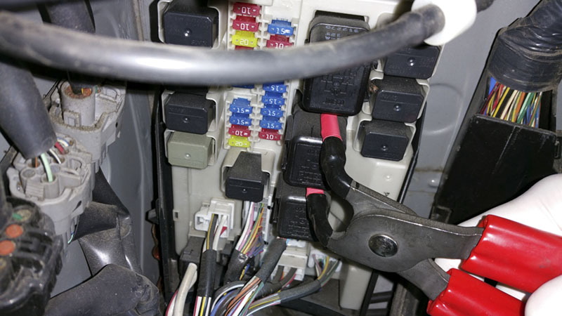
Unless you want to buy your customer a new IPDM, don’t try to remove the integral relays. You’ll damage the unit!
The IPDM is a lot smarter than a relay block, but doesn’t make most decisions on its own. The BCM and ECM issue most orders via the CAN bus. Instead of running one wire for each desired output, as would be necessary with a simple relay block, all orders from the BCM and ECM are sent via the CAN bus, which only takes two wires.
The IPDM controls the generator output via a modulated pulse width (PWM) signal. The ECM issues a charge request to the IPDM via the CAN bus, then the IPDM sends a PWM signal to the generator. The ECM also controls the cooling fan speed through the IPDM in the similar fashion. A CAN message is sent to the IPDM, then the IPDM commands low and high speed operation of the fan by energizing the appropriate relay.
The Body Control Module issues commands to turn on or off various circuits powered by the IPDM. The headlight relay, tail light relay, fog light relay, ignition relay #1, and starter relay are usually commanded on or off by the BCM. The ECM also commands the IPDM to power or depower circuits. The ECM controls the AC relay, fuel pump relay, throttle motor relay, cooling fan relays, and in an odd bit of bootstrapping, the ECM relay.
In the event of a loss of network communication, the IPDM will make some decisions on its own. This is called failsafe control. When the IPDM loses its “eyes and ears,” it defaults to actions that will allow the vehicle to be driven to a shop. If its connection with the ECM goes down, the IPDM will run the cooling fans whenever the ignition switch is on, it will turn off the AC compressor coil, and it will command the alternator to charge. If the connection with the BCM is lost, the headlights and other illumination will be turned on, the wipers and ignition will continue to function at their last state before communication was lost and the horn, fog lamps, and starter motor will not operate.
The System Benefits
I is for Intelligent
The IPDM does make some decisions on its own without consulting the ECM and BCM. One of its autonomous functions is self-preservation. The bane of control units and relays is low resistance in an output circuit. Low resistance means high current flow. High current flow means heat and oxidation of conductors and melting plastic (bad stuff for relays, transistors, and connections). The IPDM uses Smart Field Effect Transistors (FET) to limit the current output and temperature to protect itself from damage in some circuits.
Saving Power
Staying awake takes energy. The IPDM is able to go to sleep and save power when there’s not a lot going on. The IPDM doesn’t decide to go to sleep on its own; the BCM issues a sleep command via the CAN bus and the IPDM drops into a low power mode. As long as the IPDM is not doing anything it thinks important when it receives the command, it will stop transmitting on the CAN bus and enter low power consumption control mode. The IPDM will wake up when the BCM sends a wake signal, or the ignition switch is turned on, or the IPDM receives an output request from another control unit.
Avoiding a Dead Battery
How often have you seen a car towed in with a discharged battery, only to find that the map light or headlights light up as soon at the charger is connected? To err is human, and Nissan engineers recognized this and created a feature called Battery Saver, which will cut power to the headlights and map lights a while after the ignition switch is turned off. If the driver forgets to turn off the map light, no big deal; the BCM will cut power and the battery will be safe. A few owners may not like this feature for whatever reason. If you encounter one, Battery Saver can be disabled using the CONSULT on many Nissan models.
Diagnosis and Repair
Diagnosing Problems
In older systems, manual voltage testing was usually the best way to find problems. For instance, if a cooling fan did not come on at 205° F, we would probably start by checking power across the fan motor. If no power was reaching the fan, we might check for power into and out of the relay. If the relay was not switching the power, we might check power across the relay coil. If the relay had power but was not being grounded, we might check the coolant temperature switch.
Most of this is still valid, but relay control has changed. A coolant temperature sensor is now reporting to a control unit instead of to a switch directly grounding a relay. One control unit is making the decision to turn on the fan then telling another to do it in an incomprehensible language of 0s and 1s. Manual voltage testing will not reveal what the control units are seeing, thinking, or saying. Therefore, the data list on the CONSULT may be the best place to start diagnosis. It’s quick and easy to see what the control units are seeing, and find out what the control units are trying to do. With that information, you can perform intelligent pinpoint testing. With the CONSULT, you’ll also be able to use active tests to determine whether control units are capable of carrying out a command even when there is an input problem that prevents this from happening.
Replacing the BCM
A new BCM must be configured to work with the vehicle in which it’s installed. Different trim levels have different features, and if the BCM configuration and vehicle’s configuration are mismatched, problems will ensue. Assuming the BCM is still alive and talking, use the CONSULT’s “Before Replace ECU” utility in “Re/Programming, Configuration” to store both the vehicle configuration and any user customized functions. Once the new BCM is installed, use the “Select Saved Data List” function to transfer the information copied during the “Before Replace ECU” procedure. If the BCM is completely dead and won’t talk to the CONSULT, install the new BCM then use the “After Replace ECU” procedure to manually input the vehicle’s configuration. Don’t guess at the configuration! Check the configuration list in the service manual because there may be some tips on how to determine the correct parameters, then inspect the vehicle to determine its configuration. If in doubt about how to determine if a feature is installed, the owner’s manual is also a useful resource. You can find both the service manual and the owner’s manual at www.nissan-techinfo.com.
Tooling Up
As always, Nissan has some of the best “without factory scan tool” diagnostic instructions in the industry, so it’s sometimes possible to muddle through without a CONSULT. However, if you repair Nissan vehicles regularly, a CONSULT will pay for itself in time saved and lead to better diagnostic accuracy. Generic OBDII scanners won’t talk to the BCM or IPDM, leaving the technician to manually measure then study inputs and outputs while guessing what’s going on inside the black boxes. There are no barriers to purchasing a CONSULT scan tool, so if you want to up your diagnostic game, you can purchase a CONSULT at [EDIT: www.nissanconsult.service-solutions.com].



0 Comments