
Balance shafts and variable valve timing help enhance smoothness, performance, and economy
You may recall that in the last issue of Volkswagen TechConnect, we covered in detail the 2.0L EA113 belt-driven DOHC engine, which was commonly found across a variety of platforms, including mid-2000s Passat, Eos, Jetta, Rabbit, and Rabbit/GTI. Although it’s a rugged and reliable powerplant that has earned a good reputation for reliability and durability, it requires timing belt inspection at 60,000 miles, and replacement at 100,000, if not before.
That design has evolved into its more sophisticated brother, the turbocharged 2.0L TSI EA888 engine. This newer configuration features a chain rather than a belt to drive the dual overhead camshafts, so periodic timing belt checking and replacement are no longer necessary (or possible!).
This new two-liter wonder was first introduced in the 2008 model year, and has been used ever since in a variety of VW models, including New Jetta and Jetta SportWagen, Eos, GTI, Tiguan, Passat, Golf, and Beetle.
Engine Overview
The VW 2.0L TSI engine is a four-cylinder gasoline engine, based on a cast-iron block and an aluminum cylinder head with dual camshafts. Each cylinder breathes in through two intake valves and out through two exhaust valves. The head is of a cross-flow design, as you would expect of a DOHC design.
This engine is fitted with electronically-controlled, high-pressure direct fuel injection and a turbocharger that features boost pressure control via an electrical wastegate. A charge-air cooler (a.k.a. an intercooler) reduces the temperature of the pressurized intake air, allowing for more boost without the detonation that hotter air can cause.
Engine controls include a throttle valve with a contactless sensor, a hot-film mass air flow (MAF) sensor with integral temperature sensor, mapped ignition with cylinder-selective digital knock control, and, of course, COP (Coil Over Plug). A Bosch MED 17.5 engine control module listens to “everybody” and helps keep all of these components in sync.
So What’s Different?
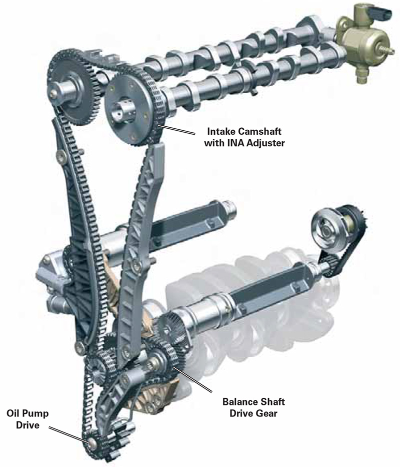
What makes this engine configuration different is the presence of two balance shafts to help minimize engine vibrations, and a clever system for varying the timing of the intake valves via the rotational position of their camshaft.
The balance shaft system is designed to reduce engine vibrations at operating speeds beyond 4,000 rpm. Given the torque curve and responsiveness of this engine design, car owners are likely to drive with enthusiasm, particularly with manual transmission models. As such, these vehicles are more likely to see higher engine speeds more often than sedate, daily-driver cars with automatic transmissions.
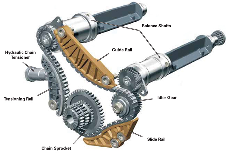
The balance shafts run at twice engine speed – exactly the opposite of typical camshaft speeds – and they run in opposite directions from each other. The balance shafts each ride in three bearings in the block and are driven by a common chain setup that incorporates a hydraulic chain tensioner plus two guide rails. The opposing rotation is achieved by means of an idler gear that interfaces between the chain sprocket and the left side balance shaft. This helical-cut idler mates with a similar gear on the front of the left side balance shaft, which generates the opposite direction of rotation.
Of particular interest is that each balance shaft, while riding in bearings pressed into the block, is also encased in a plastic pipe. This innovative design serves as a shield for engine oil returning from the cylinder head to help reduce or eliminate the churning and foaming that would result if the oil flowed directly onto the balance shafts, which, as noted above, spin at twice engine speed.
Valve Variation is the Key
One of the most effective features of the VW 2.0L TSI engine is its variable valve timing (VVT) INA system. This is actually an electronic/electrical/hydraulic/mechanical system that advances intake valve timing for optimum performance, driveability, engine smoothness, emissions control, and fuel economy. The exhaust camshafts and valves have fixed valve timing.
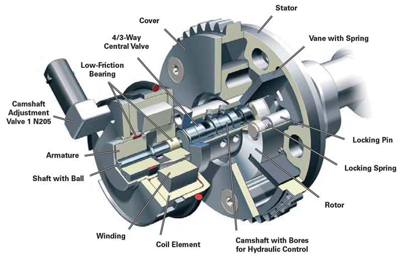
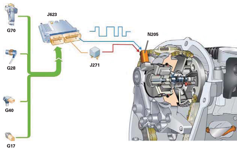
The heart of the variable valve timing system is the intake cam adjuster. This ingenious device is referred to as a hydraulic vane cell adjuster, and works by directing oil pressure to one of a number of chambers that determine the amount of camshaft advance. Parts of the system are integral with the intake valve camshaft, the remainder are contained within the valve unit itself.
The adjuster takes its marching orders from the ECM, and provides a range up to 60 degrees of crank angle advance depending on driving conditions and other parameters that dictate valve timing mapping. Sensors that help the adjuster perform its duties include those for coolant temperature, camshaft position, engine speed, and mass air flow. This system exhibits an extraordinarily fast response time and adaptability to various conditions, even during cold starts or when engine oil and coolant temperatures can soar due to prolonged idling in hot weather.
An unusual feature of these engines is the construction of the valves. The intake valves are of a fairly conventional construction, with solid chrome-plated stems and reinforced valve seats. The exhaust valves, however, are of the sodium-filled variety, which are most often associated with racing engines where supplemental cooling of the exhaust valves is needed.
The work of the sodium is quite interesting. It actually rides back and forth within the hollow valve stem. At the head end of the valve, combustion heat melts the sodium, turning it into a liquid. During reciprocation, the liquid sodium gives off its heat, turning back into a solid. It is this transfer of heat from solid to liquid on each cycle that helps keep the head of the valve cool and happy.
The Chain Gang
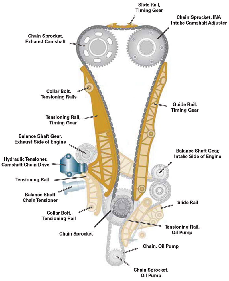
The 2.0L TSI engine features three separate gear chains (as opposed to the noisier and less-durable roller type) at the front. The innermost chain powers the balance shafts (again, at twice engine speed), the center chain powers the camshafts, and the front-most chain drives the engine oil pump. All of these chains are driven off a one-piece, three-row sprocket fitted to the nose of the crankshaft, forward of which is a spur gear which mates with the harmonic balancer. Of course, outside of all of this is a conventional ribbed belt which powers the air conditioning compressor and the alternator with a spring-loaded tensioner to make it self-adjusting.
Speaking of the crankshaft, a unique feature of the 2.0L TSI engine is upper and lower connecting rod bearing shells that differ in construction. The upper shells are constructed with a two-component composite material, while the lower shells feature a three-component composite material.
At the front of the engine lives a bearing bridge plate, which supports the camshafts and controls camshaft endplay while providing pressurized engine oil to the camshaft bearings and camshaft adjuster.
Cam Advance Actuation is the Key
In the 2.0L TSI engine the balance shafts, while of a sophisticated design, are essentially maintenance- and trouble-free, and should operate properly for the life of the engine. So, they’re something you shouldn’t expect to have to service. Similarly, the chain setups that power the balance shafts, the camshafts, and the oil pump are quite robust and are thoroughly bathed in oil, so should likewise present few opportunities for service.
Perhaps the most intricate component within the balance shaft/camshaft consortium is the cam position adjuster. As noted earlier, this device operates on the intake camshaft only, and is controlled by the ECM based on various parameters. It then takes the signal from the ECM to meter engine oil pressure to the hydraulic-over-mechanical portion of the cam position sensor, converting engine oil pressure into mechanical action that advances the camshaft at higher engine speeds, and allows it to return to its normal position at lower speeds, where a less-advanced camshaft contributes to more efficient engine operation. And it is on this cam position adjuster that we will focus our attention here.
If there is a problem related to the cam position adjuster, it will typically manifest itself with a Check Engine (MIL) light, rough-running, especially on startup, and an intermittent loss of power. If your scan tool reveals a fault code related to the cam position adjuster, it makes sense to perform the easiest tests first.
You can test the condition and function of the cam adjustment solenoid by using your scan tool or engine analyzer to scroll through Engine Electronics, Output Diagnostic Test mode, to the Cam Position Adjuster Solenoid test. This will query the solenoid and provide a report on the integrity of both its electronic and mechanical systems. During this test, you should feel the solenoid with the engine running, and listen carefully, with a stethoscope if necessary.
A properly operating solenoid will give off a soft pendulum-like “tick-tock” sound that you should be able to feel and hear. This cycling should coincide with readings on your engine analyzer. A steady, solid tick-tock will indicated a solenoid that’s operating properly. As a side note, this very quiet tick-tock will be similar to that found when diagnosing a VR-6 engine, while the 2.5L engine with VVT will emit a much louder sound from the solenoid. All of these are indications of proper operation.
If the camshaft adjuster solenoid appears faulty, the cause could be a breakdown in the electronics of the solenoid. But note that, since the solenoid uses electronic signals to meter engine oil pressure to advance the intake camshaft, insufficient oil pressure may manifest itself as a faulty solenoid. Insufficient oil pressure, of course, may be the result of a low level in the crankcase, worn rod and main bearings, or the formation of sludge in the oil and passages caused by owner carelessness in not having the oil and filter changed regularly. This is yet another reason to stress proper maintenance in your communications with customers.
With proper operation of the solenoid verified, next step is to actually measure the position of the cam timing. By scrolling through Measured Values, select the screen appropriate to cam timing. There will likely be four parameters displayed – engine rpm, cam adjuster duty cycle, the spec for correct cam timing, and indicated actual cam timing. While cam timing may jump around rapidly on your monitor, you can use Freeze Frame to lock into a particular instant for one or repeated readings for comparison with the spec.

You may encounter a vehicle in which the intake camshaft was recently removed and reinstalled or replaced, with a customer complaint that, “It hasn’t run right since.” Since the adjustment range of the 2.0 TSI engine’s VVT is 60 degrees, you may see an actual cam reading of as much as 60 degrees advanced, which would indicate that, when installed, the intake camshaft was not timed properly. Note that the predecessor to the 2.0L TSI engine, the 2.0L Turbo FSI engine, also had VVT, with maximum intake camshaft advance of 40 degrees, compared with the 60 degrees available in the 2.0L TSI. Both engines should read 28 degrees of advance at idle.
The Fix is In
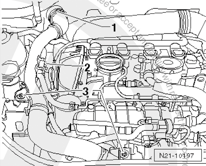
If you find it necessary to replace the camshaft adjustment valve, you’ll be pleased to know that it is a very straightforward procedure on most VW models. You simply remove the electrical connector from the valve, unscrew three retaining bolts, and lift out the valve. Your VW parts department can supply the proper valve for your particular application, and installation of the new valve is simply a reversal of the removal process, noting that you should lubricate both the sealing ring and O-ring with engine oil prior to installation.
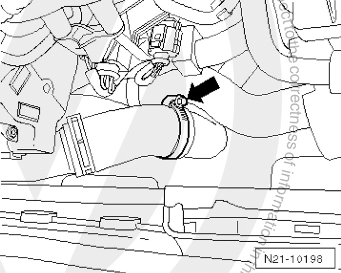
If you’re dealing with a VW Rabbit, the process for replacing the camshaft adjustment valve is a bit more involved, since it is necessary to remove the charge air duct-to-sound generator if so equipped. First you must disengage the side clips on the cover for the air duct and remove the cover. Then disengage the wire retainers to unclip the lower air duct. Remove both the lower air guide and the air guide hose. Open the latch retaining the charge air guide, unclip the fuel lines, and loosen the bolts retaining the charge air guide.
Finally, loosen the clamp and remove the charge air guide and seal the charge air guide connection with a suitable plug. This will provide access to the camshaft adjustment valve which can be removed using the procedure described above. Then reassembly of the charge air duct-to-sound generator is a reversal of the disassembly procedure.
Download PDF


0 Comments