

Timing chains are strong, but they can fail. Many technicians find diagnosing these failures difficult. Let’s shed some light on the common issues timing chains can have, so we can better diagnose and repair vehicles correctly the first time.
In the first installment of this series, we covered an overview of the entire camshaft timing system in both engines of the 2015 Nissan Altima. This time we are going to take an in-depth look at timing chains and sprockets. We will focus on the QR25 and VQ35 engines but keep in mind that some of the principles that we discuss can be applied to any Nissan timing chain engines. Nissan uses silent type timing chains, and these systems are low maintenance, strong, and very reliable. However, as with any mechanical device, they can develop problems. We will discuss how timing chains can fail. Then we will look at how to diagnose these failures, regardless of whether or not they generate a DTC. And finally, we will cover repairing failures once they have been identified.
Common Failure
The most common failure of timing chains is excessive stretching. The links of the chain do not stretch, but the pins wear and the pinholes become elongated. This wear creates a greater distance between each link, increasing the overall length of the chain. Over time, the timing chain will naturally stretch to some extent. This is normal, and the reason timing chain tensioners are variable length. As the chain stretches through normal operation, the tensioner extends to take up the slack. However, if the chain stretches excessively, engine performance will suffer. The tensioner can compensate for the increased length, and keep the chain tight and quiet, however the chain is still physically longer. This causes valve timing to be retarded, and retarded valve timing causes diminished engine performance. At some point, the ECM may report a DTC, such as P0335 Crankshaft Position Sensor, P0340 Camshaft Position Sensor, or P0300 Multi Cylinder Misfire. However, these codes have many possible causes, and can sometimes lead us down the wrong path during diagnosis.
The most common cause of excessive timing chain wear is lack of lubrication. This comes down to one thing: proper maintenance. Oil must be changed regularly, with high quality oil of the correct viscosity, and a Genuine Nissan Oil Filter. The majority of engine wear occurs upon startup, because oil pressure is gradually lost while the motor is at rest. When the motor is started, it spins briefly with little or no lubrication. Genuine Nissan Oil Filters combat this with high quality anti drain-back valves, which keeps oil pressure in the engine while it’s at rest. The difference may seem minor, but over the life of the vehicle it adds up. Even when Genuine Nissan Oil Filters are used, the oil still must be changed at the recommended intervals. Extending oil changes past these intervals promotes sludge formation. This sludge, a product of oil mixing with blowby gasses, clogs oil passages, and greatly contributes to lubrication issues.
Diagnosing Chain Wear

The QR25 trace should look like this. Notice how the pulses align with each other. If the camshaft pulses are shifted to the right, then the timing chain is excessively stretched.

The VQ35 trace should look like this. Notice how the pulses align with each other. If the camshaft pulses are shifted to the right, then the timing chain is excessively stretched.
On older engines, we can check the timing chain mechanically. This procedure can only be used on engines that use a non-ratcheting timing chain tensioner. We must be able to see the camshaft sprockets. Most Nissan engines have a cover that can be removed to achieve this. Once we have gained access to the camshaft sprockets, the crankshaft pulley should be rotated clockwise two full rotations to take up any slack that may be present. Now slowly rotate the crankshaft pulley backwards, in a counterclockwise direction. Watch the camshaft sprockets and stop rotating the crankshaft pulley as soon as the camshaft sprockets move. If the crankshaft pulley has been rotated more than 5° before the camshaft sprockets move, then the chain has excessive wear and should be replaced.
Newer engines, like the QR25 and VQ35 have ratcheting timing chain tensioners that do not retract once they have been extended. The mechanical check will not work for these engines. Furthermore, the mechanical check is labor intensive and requires removing covers that may be difficult to access. A more appropriate check for timing chain wear can be performed with the aid of a dual trace oscilloscope. The Nissan CONSULT III plus is capable of tracing these patterns.

Cylinder 1 on the QR25 is at TDC when the single mark, B, is aligned with the timing pointer, A. Be sure to use the single mark, B, and not the white timing marks, C.

When cylinder 1 is at TDC compression with the QR25, its cam lobes will face out and away from each other as shown here.
Connect the lead for one trace to the camshaft position sensor (PHASE) signal wire, and connect the other lead to the crankshaft position sensor (POS) signal wire. Then, disable any variable valve timing by disconnecting the connector to the valve timing control solenoids. Start the engine and let it warm up to normal operating temperature.
Once the engine is warm and stabilized, take a look at how the traces line up with each other. The crankshaft signal will have high frequency pulses with larger gaps that indicate a piston at TDC. The camshaft signal will have a specific set of voltage pulses that indicate which cylinder is at TDC compression. These pulses should line up in a certain way. How they line up varies depending on the engine, so be sure to refer to the appropriate service manual information.
For the QR25 engine, the leading edge of the crankshaft TDC pulse should line up with the trailing edge of the camshaft signal pulse. For the VQ35 engine, the trailing edge of the crankshaft TDC pulse should line up with the leading edge of the camshaft pulse. A stretched timing chain will cause camshaft timing to be retarded, and you will see the camshaft pulses later than normal. When graphed on the oscilloscope, they will be shifted to the right and no longer line up properly with the crankshaft pulses. There are other possible failures that can cause this condition. An improperly indexed flywheel, for example, will cause the pulses to all be off by the degree of misalignment. However, this can only happen if the flywheel is installed incorrectly. It will never happen naturally, due to engine wear. Another possible cause is a camshaft sprocket that has spun on its hub. If this is the case, the timing chain will require removal to access the sprockets, and the procedure will be the same. Although this test requires having access to an oscilloscope, it is fairly simple and cheap to perform, and no engine components need be removed.

To find TDC for cylinder 1 on the VQ35, align the grooved line WITHOUT color with the timing indicator on the front cover.
Once it has been determined that timing chain or sprocket wear is excessive, the system must be serviced. Servicing the QR25 timing chain requires removing the engine from the vehicle. The VQ35 timing chain can be serviced in the vehicle, but it is much easier to access if the engine is removed.
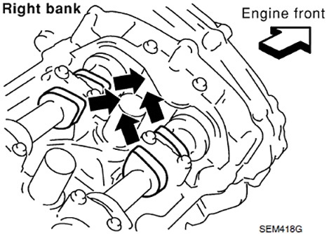
When cylinder 1 on the VQ35 is at TDC compression, its camshaft lobes will face up and in towards each other as shown here.
We’ll outline procedures common to all timing chain engines, and some specifics of these two engines. It is imperative that you consult the Nissan factory service manual before any repairs begin, as this article will not cover every detail required to service the timing chain.
Disassembly

On the VQ35 engine, cylinders 1, 3, & 5 are on the rear bank and are covered by the intake manifold. However, cylinders 2, 4, & 6 are easily accessible. When cylinder 4 is at TDC exhaust, cylinder 1 is at TDC compression.
Regardless of the engine being serviced, cylinder 1 must be at TDC compression before any repairs can begin. Cylinder 1 will always be the cylinder closest to the front of the engine. On the VQ35, this is the first cylinder on the right bank, the bank closest to the firewall. There are a few different ways of finding TDC compression on cylinder 1, choose the most appropriate for the engine being serviced.

Once all of the bolts are removed from the VQ35 front timing cover, it can be removed. Pry the cover off by using a suitable tool inserted into the notches shown here.
The crankshaft pulley has a single notch that indicates TDC. This notch should be lined up with the timing indicator on the front cover. Be sure to use the appropriate notch, as most crankshaft pulleys have multiple marks.
The QR25 pulley has a single unpainted notch for TDC, but also 2 white paint marks that are used for measuring timing. When aligned, the engine is at TDC on cylinder 1, but we don’t know if the cylinder is on the compression stroke or the exhaust stroke. If the valve covers have been removed, the camshaft positions can be used to determine this. The QR25 engine will have the cam lobes on cylinder 1 facing outwards and away from each other when on compression. The VQ35 will have cylinder 1 cam lobes facing up and in toward each other on compression. If the valve covers have already been removed, this is the quickest way to determine if cylinder 1 is at TDC compression. However, removing of the valve covers is not required for servicing the timing chain.

Carefully inspect the timing chain for wear if you do not already plan to replace it. Any cracks or looseness in link pins warrants replacement.

Here we see a diagram depicting the proper application of RTV on the front cover. Notice that the bead thickness varies, and is to applied around the outside of some of the bolt holes. Be sure to follow the diagram for the engine you are working on.
If the valve covers have not been removed, the best way to find TDC compression is with the use of a compression tester hose. Remove the spark plug from cylinder 1, and install the hose. Now, rotate the engine clockwise and stop about 90° before TDC. Place your thumb over the hose and rotate the motor to TDC. If pressure is felt on your thumb, then the cylinder is at TDC compression. If no pressure is felt, the cylinder is at TDC exhaust and the engine must be rotated one full turn to be at the correct position. This procedure is simple enough on the QR25, but the VQ35 poses an interesting challenge. Cylinder 1 spark plug cannot be accessed without removing the intake manifold. So on this engine we will instead use cylinder 4, the middle cylinder on the left bank. Cylinder 4 is mated with cylinder 1; they are both at TDC at the same time, but on opposite strokes.

The colored links, A, of the QR25 main timing chain must be aligned with the mating marks, B, of the camshaft sprockets.
When cylinder 4 is at TDC exhaust, cylinder 1 is at TDC compression. Use the same procedure, and when no pressure is felt on your thumb. Cylinder 4 is at TDC exhaust. Therefore cylinder 1 must be at TDC compression.
After the engine is set to TDC compression, install a ring gear stopper to keep the crankshaft from rotating during repairs. Now, timing chain removal can begin. Remove the crankshaft pulley and front timing cover to expose the chain system. You may notice that the colored links of the chains do not line up with the notches on the sprockets. The engine can be rotated so that these links line up, but it is not necessary. The colored links are really only used when installing a new chain, which we will likely be doing. If the chain is to be reused, simply mark the links that do line up with the notches in the sprockets with a paint pen. Then reinstall them in the same place. It is common for the main chain to be replaced, but the balancer chain, on the QR25, or the secondary chains, on the VQ35, to be in good condition and reused.
Release the timing chain tensioners, then remove them along with the guides. Inspect the guides for wear, and be sure the tensioner piston moves freely. The main timing chain can now be removed and inspected. Look closely for cracks or abnormal wear. Next, remove and inspect the sprockets for wear. The longer the engine has been driven with a stretched timing chain, the more likely it is that the sprockets will have excessive wear and require replacement. If the timing chain is to be replaced it is always best to replace all components that it contacts. Compared with the cost labor involved with timing chain replacement, the cost of new sprockets, guides, and tensioners is minimal.
Use this opportunity to also inspect for sludge buildup. If any sludge is observed, it must be thoroughly cleaned before installing any components. The VQ35 utilizes two small mesh filters placed near the center of the front timing cover, and the QR25 uses one filter in the upper left area of the front cover. These filters protect the valve timing solenoids. Be sure to inspect these filters for debris, and replace them if any blockage is found. There are also multiple O-rings that will be removed with the front cover. These should never be reused, even if they appear to be in good condition. When replacing the timing chain on the VQ35, the water pump should be replaced as well. After all components have been inspected and the timing case has been cleaned, installation can begin.
Installation
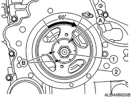
The QR25 crank pulley bolt must be tightened to 31 ft.lbs. and then an additional 60°. The bolt has six stamps on it, each 60° apart. Simply mark the pulley at one stamp then tighten the bolt until the next stamp lines up with the paint mark.
At this point, I must reiterate, that it is essential that you have read and comprehended all procedures outlined in the service manual. In particular, torque specs and tightening sequences. If these are not followed precisely major problems can arise. The front covers are sealed with liquid gasket, referred to by Nissan as “Ultra Grey.” This must be applied exactly as stated in service manual, as there is a specific pattern of application.
Be sure you are ready to reinstall covers before the sealer is applied. It dries quickly and must be installed within five minutes of application. Always check timing marks multiple times during the process, ideally after each new component is installed. It is easy for the chain to slip a tooth between steps. If this goes unnoticed, engine damage may occur and the entire job will need to be redone.
The installation of the QR25 timing chain is fairly straightforward. Install the sprockets first. When installing the camshaft sprockets be sure to line up the indexing grooves with the dowel pins on the camshaft. Crankshaft sprockets will be aligned by the keyway in the crankshaft snout. Next, install the balancer chain, being sure to align the colored links with the mating marks of the sprockets, then the balancer chain tensioner. Now we are ready to install the guides and the main timing chain. Once again, be absolutely sure all mating marks are aligned with the colored links. The last component to be installed is the main timing chain tensioner. Install it with a stopper pin holding the tensioner fully retracted. Recheck all alignment marks then remove the stopper pin. Be sure the tensioner plunger extends and moves freely. Make one final check of all alignment marks then install the front cover and crankshaft pulley.

Here is a rear view of an assembled secondary chain for the right bank of the VQ35. The colored links, H & C, must be aligned with the mating marks, B & G. The left bank secondary chain will be reversed.
The VQ35 timing chain installation follows a similar procedure, however instead of a balancer chain, there are two secondary chains. The secondary chain installation is unique in two ways. The first difference is the fact that the secondary chain tensioners will be installed first. The second difference is the fact that the secondary chain must be assembled with the camshaft sprockets before being installed on the engine. The sprockets for the left bank are the same as for the right bank, therefore, they all have both mating marks. These marks are on the rear of the sprockets. The right bank will use the single circle mark on the intake sprocket, matched with the single colored link on the chain, and the double oblong marks on the exhaust sprocket, matched with the double colored links on the chain. The left bank will use the opposite marks. If this seems a bit confusing, just keep in mind that both dowel pin grooves should face upwards. As the mating marks on the camshaft sprockets are on the rear, they will not be visible once the sprockets are installed. To make rechecking alignment easier, a paint mark should be made extending from the mating marks up to the teeth of the sprockets.

To make rechecking VQ35 alignment easier, make a paint mark extending from the mating mark to the teeth of the sprocket.
Once assembled, the secondary chains and sprockets are ready to be installed. Line up the grooves in the sprockets with the dowels on the camshafts, tighten the bolts to spec, release the secondary tensioners, and check that they are still properly aligned. After this is done, the main chain can be installed. Align the colored links on the main chain with the stamped marks on the front of the sprockets. Then install the three guides, and finally the main tensioner. Release the tensioner and recheck all alignment marks. Once it is confirmed that the timing marks are lined up, install the front cover and crankshaft pulley.
Final Check
After all repairs are completed, rotate the crankshaft pulley to ensure nothing is binding. Be sure all fluids are at the correct level before starting the engine. Upon initial startup, there will be a thumping or rattling noise heard for the first few seconds. This is because the timing chain tensioner doesn’t function until oil pressure has built up inside it. The noise is normal, and it should go away quickly. Check for any leaks and abnormal noises. Let the engine warm to operating temperature, and be sure the cooling fan cycles at least one time. Allow the vehicle to cool and recheck all fluid levels. If no problems are found, the repair is complete and the vehicle is ready for delivery to the customer.


0 Comments