
The second installment of our man Greg’s magnum opus on rings talks about how they’re all part of a system that includes various clearances, gas porting, and piston rockover, shape, and stabilization.

With an axial width of only 0.0236 in., this ring really is thinner than a dime. To an old mechanic like me, this is really amazing stuff.
This is all a much bigger system than you might suspect, as we will soon discuss. The rings’ performance is wholly dependent on the piston, the piston ring groove accuracy and finish, the cylinder wall, the wall finish, ring sizing, preparation, and bore prep prior to installation. The ring can’t do what it should if the parts it interfaces with aren’t right. From the rings’ point of view, the piston must present a stable platform for operation. Rockover should be minimized, the ring groove must be accurately cut and finely polished to allow sealing in the groove, the side clearance and back clearance must be correct, and piston overall dimensions must be appropriate for the application.
For ring side clearance, we should see something on the order of .001-.0015 in. For back clearance – that is, the amount below the piston land that the ring sits on when viewed straight on – we should see something at or more than .005 in. recession, and this is a case where “less is more” until we get to the point that the ring grows enough to grab the bore with heat and load. We don’t want the ring proud of the groove – and it should be intuitively obvious that if there is lower volume behind the ring, it will push out faster and be in more intimate contact with the bore sooner during the compression stroke if back volume is minimized.

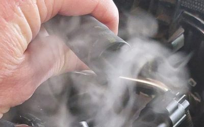
To check ring back clearance before grinding and installation, simply insert the ring into the groove backward and roll the ring around the piston’s circumference. You should check all rings and all pistons because an error may be caused by either a ring improperly finished, or a piston improperly machined. Here you can clearly see that the ring is standing proud of the groove. This would have been a real problem had we not caught it during our mock-up and inspection process.
A good friend of mine was once involved with another builder who failed to check the back clearance during the build and the ring was actually a little proud of the groove. On the dyno, the engine would start and begin to pull, then suddenly slow and stall. It would immediately restart and repeat the same behavior. Needless to say, there were a lot of ignition and fuel parts replaced before that one got figured out!

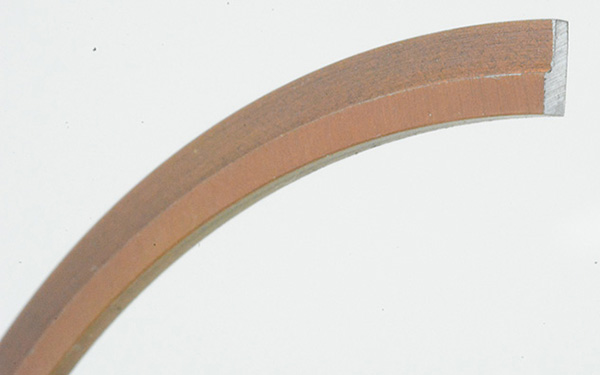
Thinner faces and less total square inches of contact with the cylinder wall equals less friction. You can see how thin this .043 in. two-piece gapless top ring has compared to the dime clamped next to it. It’s a long way from a 5/64th or a 1/16th in. ring, isn’t it? Grinding them is a pain in the hindparts, too.
Nearly all racing applications make use of gas porting, either drilled down from the top or drilled radially in above the top ring. Gas porting just allows the ring to achieve a tighter gas seal earlier in the compression stroke. This is a good time to squelch the old wives’ tale about gas porting. It doesn’t increase bore wear. Never has and never will. The ports only cause the ring to actuate quicker as the piston comes up on compression. The end gap and the side clearances are such that compression and combustion pressure will always find a way behind the ring to press the ring into the bore – it just happens later without gas ports. We rely on cylinder pressure to apply the ring firmly to the bore, and always have. Gas porting just “applies” the ring sooner and more consistently.
Any time the ring stands proud or proceeds from the groove, you run the risk that the ring will grab the bore and stall the engine. How much back clearance is just right is dependent on the ring’s distance from the piston top (exposure to heat), its axial width (thickness), its radial width (distance from ring outer diameter to inner diameter), and its rate of growth with temperature. This is high-performance work (there is rarely “one right answer”), and sometimes you just have to cut and try to make it work.
Rockin’ and Rollin’
Piston rockover causes ring control issues because the ring moves from a circle to an ellipse as the piston rocks over center, which is a function of changing rod geometry as the crank moves through top and bottom dead center. We don’t use piston pin offset in racing applications because doing so increases skirt friction as the piston rocks into the major thrust face sooner as it moves up the bore during compression. In fact, pin offset is rarely used any more at all – even in production engines. During rock, the ring end gap can vary slightly; the ring contact varies from top lower to bottom upper to face centered to top upper and bottom lower as the piston rocks over center. Rockover is caused or affected by stroke length, compression height, skirt length, skirt clearance, and piston head diameter cutback. Stroker engines can suffer from some of the worst cases of rockover as the piston is pulled farther out of the bore over bottom dead center, which explains some of the oil consumption issues often associated with stroker builds.
The piston head is typically cut back between .030 to .090 in. less than the largest skirt dimension to allow for piston head expansion due to heat and carbon formation above the top ring, although that’s not a hard-and-fast number anymore, either. The Pro Stock guys are always experimenting and rumor has it that they might run piston head diameters with less than .015 in. cutback. Of course, they’re taking it apart every 20 runs, something most racers hopefully aren’t doing.
Shapely
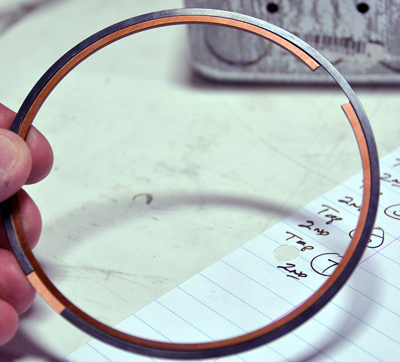
Gapless rings have a main ring that’s shaped roughly like an “L,” and a side rail that looks like a thinner-than-standard oil side rail without the chrome face. The gapless rails come in various axial thicknesses, from .010 in. up, and drop into the groove formed in the main ring, and almost lock into place. Gapless rings normally run a lot more gap than conventional rings, so read the instruction sheet for the gapless design carefully. It’s not uncommon to see end gaps range from .024 to .036 in., depending on bore diameter.
Piston shapes are more extreme now as racers and manufacturers look for any advantage. Let’s face it, friction is a big problem in a racing engine and the more you reduce friction the more you reduce the parasitic power losses and the more power is available for moving the car down the track. Friction increase is linear with engine speed and increases rapidly with cylinder pressures and rpm, so any friction reduction you gain is increasingly beneficial at higher operating speeds. Rings and pistons make up roughly 50% of the frictional losses in an engine, another 25% is lost to the main and rod bearings, and the balance is lost to seals, other bearings, and the valve train. If you’ve got a choice between using up power to overcome friction and using up power to go faster, choose going faster.
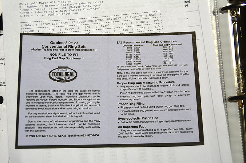
If you use Total Seal’s rings, make damn sure you follow the correct set of directions. They make both conventional rings and gapless rings, and there’s a purple instruction sheet and a green instruction sheet. Purple is for conventional sets or gapless second rings, which are popular with the alcohol-burning guys because they minimize crankcase contamination, and green is for gapless top ring sets.
Shorter, lighter pistons with smaller overall contact patches above and below the rings naturally have less friction. The fewer square inches of material there is in contact with the bore, the lower the coefficient of friction; that’s just common sense. BUT, it comes at a premium. Piston makers are utilizing reduced contact/anti-detonation grooves above the top ring, increasing the cam (oval shaped skirt, as seen from the top) and barrel (barrel shaped as viewed from the side), as well as reducing overall length from head to skirt bottom. They are also taking advantage of narrow ring options that eliminate the extra weight of pin buttons or oil control ring support rails by moving the overall ring pack up and out of the pin bore. Piston weight goes down, which reduces rod bolt load (particularly during overlap where the cushion of compression isn’t there) along with a dramatic reduction in piston to bore friction. But the stability of the piston in the bore goes to hell; it’s rocking over to the tune of .020-.075 in. Combine that with reduced ring axial and radial widths and lower ring tensions to further reduce friction and reduced ring mass to lessen the effect of inertia (a body in motion tends to remain in motion; a body at rest tends to remain at rest) as the ring pack reverses direction at the top and bottom of every stroke, and you’ve got yourself the very definition of a system on the edge of being dynamically out-of-control.
You NEED a light piston to keep rod bolt loads reasonable and your high rpm assembly alive, you need as little friction as possible, and you need thin, low-tension, low-friction ring packs that can provide oil control and compression and blow-by control. It can be done with the latest piston and ring designs, but anything you can do to stabilize the piston helps. A fairly new development is skirt-applied abradable powder coatings used to reduce skirt clearance and control rockover. This isn’t just a spray lubricant or moly like you’re used to seeing. This is a coating that has to be sanded away to fit the piston at zero clearance to the bore and requires a very specific break-in cycle to make it work correctly. More information is available on this technology at the Line to Line Coatings website where you can see what they’ve been doing do stabilize the piston and what kind of results they are getting from that process.
Other considerations that will affect your rings’ performance include crankcase capacity, windage control, oiling system type, and bearing clearances. If you increase stroke, a popular engine modification these days, you must also increase the pan or crankcase capacity by an amount similar to the displacement increase. Adding 50 cubic inches above the piston adds 50 cubic inches below the piston, and that means more pumping, and swinging a larger stroke can mean more windage in the pan. Oil clearances and throw-off on the low bore walls is an oil-control challenge with lower-tension oil rings. Putting a low-tension ring in the middle of a flood of oil will probably result in a consumption complaint, so drop the pan floor by going to a larger volume oil pan and add a well-designed windage tray or scraper or both and give the rings at least a fighting chance at functioning as designed. If it’s an option, a dry sump oiling system helps to scavenge the oil, produces a partial vacuum in the crankcase, and de-aerates the oil, which in theory can allow you to close up bearing clearances, thus reducing oil throw-off onto the cylinder walls from the rod bearings.
 |
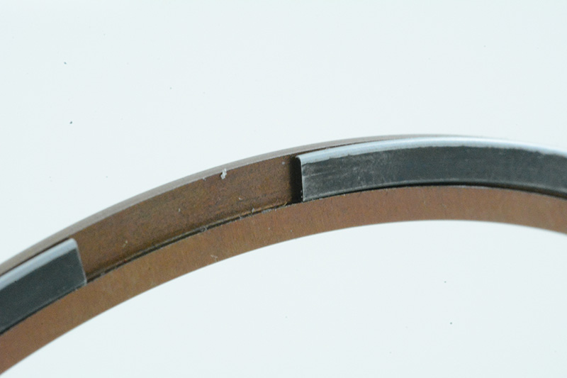 |
| Here are a couple of examples of gapless top rings and how the rail sort of locks into the main ring. I say “sort of” because it really doesn’t lock in in the traditional sense, but it does catch well enough that it will follow the ring compressor into the bore without a problem. The first time I loaded these into a block I thought for sure I was going to have a fight on my hands. | |

I used a dime to show you the scale of this conventional top compression ring, made by Total Seal. It’s a .6 mm axial width, .102 radial width, Diamond-finished, C-72 face-coated, barrel-faced steel ring, and it’s so pretty it makes me want to buy a gold chain and wear it around my neck. This is the kind of ring the Pro Stock guys were using three years ago. Wouldn’t you just love to see what the cutting edge looks like now? Probably scare you to death…
If that’s not an option, you can investigate a vacuum pump to augment pan evacuation and entrained air removal. Just remember that on a wet sump engine the vacuum pump can affect the oil pump’s ability to pick up liquid lube from the pan resulting in oil pressure fluctuation or oil starvation if you run too high a vacuum level. Well evacuated pans often show significant horsepower gains on the dyno, so it’s worth investigating.
Lowering internal engine pressure is used to augment a well-designed system; it’s not a fix for a poorly designed system. It’s for removing air from the oil, thereby improving the oil wedge and reducing bearing wear.
Ring Selection and Prep

Just to keep our perspective, here’s a conventional top, ductile iron moly-filled 1/16th in. ring. Compared to the .043 and .0352 in. rings, it looks like a giant, and it should – it measured .062 in. axial width. Smaller, thinner, lighter – that’s where it’s all going.
There are far too many options available to make a decision on which ring to use in your particular application on your own. Materials used in ring manufacturing include ductile iron, steel, tool steels, chrome, and moly. Profiles might be tapered, hooked, or barrel faced, and there are numerous special processes including coatings and high-tech polishing as well as an almost unlimited selection of axial and radial thicknesses, standard, gapless, and tension options, and special application options. You simply MUST consult with the technical service people to get the answers you need and the best recommendation for your application. If you are running special axial and radial thicknesses, or blown or nitrous applications, you will also need to consult with your piston supplier to make sure that the top ring is distanced correctly from the top and that the ring grooves are custom-cut to fit your ring selection. While most ring grooves are cut perpendicular to the bore wall, there are still some pistons made that have grooves that tip the ring slightly upward, so be aware of that possibility.
I have to admit I’m a fan of Total Seal gapless rings. The ones we’ve tried (circle track and drag engines) have worked well. The power improvements to be made with this design aren’t just from compression gains, they also produce other benefits in terms of a stronger carb signal, cleaner engine oil, less bore corrosion between races, and improved exhaust scavenging. To get the maximum return from their use, however, you’ll have to tune to their strengths. You might find that you need a different camshaft, carburetor or engine timing curve to get the most from the combination.

0 Comments