
This second installment of our series discusses high-tech testing with various tooling to help diagnose the high pressure fuel system.
Note: Read and understand all cautions and safety procedures before working with the TSI/FSI fuel system.
To repeat what we said in Part 1 of this series: Electrical issues can play a major role in service and repair. The battery and installed controllers should be treated as an integrated system. The power supply discussed in Part 1 of this series is part of a system that can be under stress depending on the environment the systems are subjected to. Repairs, diagnostics and vehicle research should begin with a stable and effective power supply.
Basic knowledge
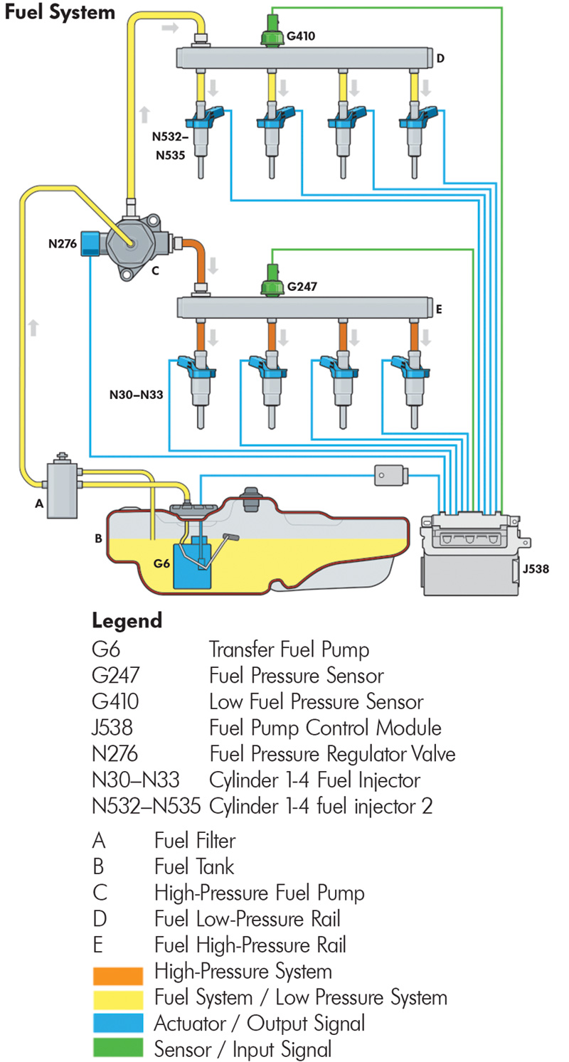
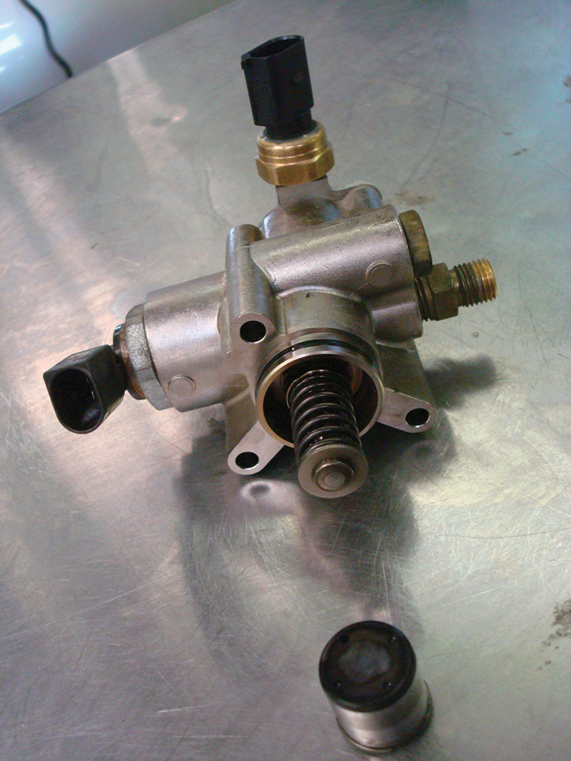
Compared to a port-injected engine, the basics of how the engine operates are very similar. The one major difference is how fuel and air are delivered to each cylinder. All models and all configurations of a gasoline direct injected engine will have these components that differ from those used in a port-injected model.
Currently, all direct-injection models employ an electric fuel pump and a fuel pump control module that is controlled by the ECM. The fuel pump control module activates the electric fuel pump via duty cycle, depending on load and temperature demands. The regulated fuel supplies the mechanical high pressure pump(s). Depending on the engine configuration, you may see more than one high pressure pump. For example; the four-cylinder engine has one pump as opposed to an eight-cylinder engine having two pumps (one per bank).
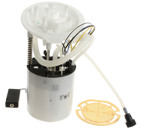
As noted in our previous installment, the fuel pump G6 and fuel pump control module J538 are located under the rear seat access panel.
Technical data
- Idle speed cannot be adjusted; it is regulated by idle stabilization via ECM.
- Engine speed limitation is via fuel injector shut-off and controlled by the ECM.
- Fuse 28 should be the power supply for the fuel pump control module J538 (refer to the correct schematic).
- This is a duty cycle system.
- Fuel pump control module J538 provides a pulse width modulation signal to fuel pump G6.
- Low fuel pressure sensor G410 measures fuel pressure sent from the fuel pump G6 and sends that data to the ECM J220.
- Low fuel pressure sensor G410 is attached between fuel pump (FP) G6 and the high pressure mechanical pump.
- If If reference pressure deviates from the programmed map within the ECM, the ECM will increase or decrease the PWM signal (in Hz) to the fuel pump control module (FPCM). In turn the FPCM will send a PWM signal (in kHz) to FP G6 to achieve the desired pressure.
Running Conditions & Live Data
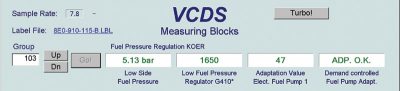
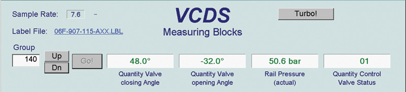
The two “VCDS Measuring Blocks” images indicate a normally operating fuel pressure system.
What are we looking at and why
The first image indicating group 103 field one, offers an average (actual) ECM controlled low pressure value via low fuel pressure sensor G410 from G6 at idle. The second image indicating group 140 field three, offers an average (actual) ECM controlled high pressure value via fuel pressure regulator N276 at idle.
NOTE: To service the fuel system, fuel pressure MUST be relieved using the following procedure.
- Remove the fuse (usually fuse number 28) at idle, and take notice of group 140 field 3.The indication in field 3 will drop very quickly after one to two minutes, because the mechanical high pressure pump is no longer supplied with fuel from the electrical fuel pump from the fuel tank G6.
- The indication must not drop below 6 bar, because otherwise the engine will shut off, risking catalytic converter damage.
- Switch ignition off once an indication of approximately 8 bar is achieved.
- The fuel rail will still be filled with fuel, but it will no longer be under high pressure.
- Now, components or lines can be opened. Place a clean towel around the connection in order to capture escaping fuel.
An extreme test and pushing a few limits

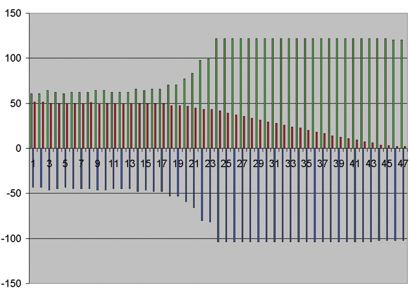
Capturing live data while simulating a failed pump offers an insight of how the high pressure pump behaves. Looking at this image, data was captured in group 140, fields 1, 2 and 3 and placed within an excel spread sheet.
The capture began when the fuse was removed until the engine stalled.
So why are the green and blue lines moving in opposite directions?
Simply, view it as a check and balance for the Quantity Valve. The spreading values when aligning the red line dropping means that the Quantity Valve (ECM controlled) is opening at a quick rate to maintain idle.
Fuel pressure loss, measured from the low side and high side, plays a critical role that the ECM is attempting to maintain. The only option is to allow far more pressure and flow than the ECM can keep up with. The immediate loss of fuel pressure drives the ECM to control the Quantity Valve rail pressure to its absolute limit.
So what does a Pulse Width Modulation (PWM) (or duty cycle) fuel pump control look like?
The violet trace indicates the pulse width at idle. The more load induced, the longer the pulse width commanded by the ECM.
This is only a test to monitor and examine how the low side pressure transducer behaves with a known perfect pump.
If the fuel system was disabled, expect all lines to flatten in short order.
Note:Volkswagen-approved special tools, lines, and attachments must be used within these fuel systems.
The yellow trace is another pressure transducer added in parallel to the OEM transducer to test relatively good quality pressure transducers on the low side with an oscilloscope.
The blue trace is the OEM transducer measured at the low side.
These specific pressure tests were captured directly at transducer G410.
Since the high pressure pump was removed, the cam shaft count is three lobes only. If the scope image is extended, every hash on the blue trace measuring every third lobe will indicate that the ECM is controlling pressure every third stroke.
These simple oscilloscope tests (without any fuel line attachments) can be accomplished directly at the ECM or at the pressure transducer.

The low side pressure transducer test should be viewed as distinct peaks and valleys, the high side pressure transducer test however should be nearly flat because of some small factors (testing at idle):
- (A) the larger inner diameter of the rail
- (B) very little fuel is consumed (short injector PW), maintaining constant rail pressure.
Therefore, when increasing idle or load requirements:
- Expect increased FP pulse width.
- Expect increased high pressure.
- Expect longer injector PW.


0 Comments