
Ignition spark timing, generation, and delivery are crucial for proper engine function. Here are the most common ignition systems used in Nissan vehicles, and information to better understand their operation, interaction, diagnosis, and service.
 Ask the average person about what an engine needs to run and you’re likely to get “spark plugs” as one of the responses. The ignition spark is fundamental in both concept and function to the workings of a combustion engine. Nissan has developed and changed ignition spark management over the years in order to meet their rigorous demands for increased efficiency and reliability.
Let’s take a look at the most common design called coil-over-plug, or a direct ignition system (DIS). We will cover how a coil-over-plug system is implemented, who the players are and how they work together. Our goal is not to analyze the nitty-gritty of oscilloscope outputs, but rather to know when and why such tools are necessary in figuring out problems with modern spark management.
Where to Begin
We should start by acknowledging that there are multiple ignition designs that Nissan has historically implemented in their vehicles. Centralized coil packs, distributors, and waste-spark methods are all fading out, giving way to the coil-over-plug implementation. Today, the wide availability of cost-effective micro-controllers permits Nissan to scale down the ignition system, removing components like separate igniters, vacuum-based timing controllers, or ignition cables from the list of possible breakages. Likewise, network-shared data obsoletes the distributor assembly that once housed a redundant cam sensor and igniter for its control feedback loop.
The key is simplicity. Technicians may have once had to check points and verify dwell on a misfiring vehicle, but now “it’s probably just a bad coil.” Yet, how did we get to this point where failures are often conveniently compartmentalized? Plus, how do we technicians evaluate a digital system that can seem to be working during testing? Let’s start by knowing what we’re working with.
The Brains of the Operation

Sensor inputs
Any Nissan vehicle’s electronic control module (ECM) manages its ignition. This seems self-evident, as it should, but we must discuss what exactly is being managed. First, the ECM determines both when and for how long an ignition event should be timed. Then, the ECM prepares these two points of data into a package that is referred to as a singular “ignition timing signal.” Lastly, the ECM transmits the timing signal to the power transistor, a portion of the ignition coil assembly.
 to begin spark generation.")
This ignition map from a 2000 Maxima shows signal pulse width versus engine rpm. Point A is how far in degrees Before Top Dead Center (BTDC) to begin spark generation.
The ECM creates different spark durations by controlling the pulse width length of its timing signal to the power transistor. A longer signal pulse width ensures that the duration of the spark remains sufficient to ignite the air-fuel mixture. Once ignited, the burn time of the air-fuel mixture is constant. Therefore, to ensure complete burn as rpm increases, the ECM must determine when to generate an ignition event. An ignition coil requires some milliseconds to charge, and a flame front requires more milliseconds to propagate; therefore, the command for the coil to begin the process must occur in advance. Otherwise, the ignition event will occur at the incorrect time, resulting in knocking, incomplete burn, or misfire. The purpose of ignition spark timing has not conceptually changed with coil-over-plug systems.
The ignition timing data points live within the software of the ECM in a so-called “map.” Just like fuel injection timing, the computer uses calculated load and multiple sensor inputs to determine how to structure the ignition timing signal. Crankshaft and camshaft position sensor operation is critical to ignition timing. The data values retrieved from the map will constantly change based on driver input, as well as passive considerations like fuel economy and emissions.
The Inner Workings of an Ignition Coil
Each DIS ignition coil assembly is made up of components that are members of the primary or secondary circuit. Think of the primary side as low voltage control and the secondary side as high voltage action. On the primary team, we have the connector, power transistor, and one half of the internal coil wire windings. On the secondary team, we have the other half of the coil wire windings, the insulator boot, the ground electrode (spark plug), and the condenser, if applicable.
Primary Side’s Quarterback

The transformer circuit diagram shows clearly that the primary and secondary circuits don’t actually connect. The solid vertical lines represent the magnetic core and its generated field as the go-between.
The power transistor is often referred to as the “coil driver” because it controls the rest of the ignition coil assembly. Unlike a relay switch that physically moves, a transistor switches by electrically changing internal state. Furthermore, a transistor can amplify input voltages based on signals from its other contacts. In an automotive ignition coil, the power transistor takes the ECM signal, amplifies it, and switches on a ground for the primary circuit to begin current flow into the primary side coil windings.
The word “coil” refers to the two sets of coiling wires around a magnetic core, and is an electronics device called a transformer. The transformer components straddle the dividing line between primary and secondary sides. Both sides have a specific number of insulated wire windings that wrap around the core, but the primary circuit is not directly connected to the secondary side. Both primary and secondary circuits have their own paths to ground. In all automotive applications, the primary side has fewer windings than the secondary side in a manufacturer-proprietary ratio (about 1:100). So, if they aren’t connected directly, how does the current flow?
Induction
When the ECM provides a pulse width timing signal to the power transistor, the primary circuit is grounded, causing current to flow through the primary side windings. In a phenomenon called induction, an increasing electric charge builds up on the magnetic core in the form of a magnetic field. Then, when the timing signal stops, the power transistor opens the primary circuit’s ground, suddenly stopping current flow. Without flow, the magnetic field collapses. The field collapse induces current to flow through the secondary circuit where the only ground remains. Because the secondary side has more windings, the induced voltage is greater, but the original current is reduced (conservation of energy).
Spark
At this point, our secondary circuit is energized with a huge amount of induced voltage. The spark plug ground electrode is the only ground in town, so the high voltage forces the current to arc across the gap. It sounds easy for this jump to occur, but in reality there is a large amount of resistance at the secondary ground. There is supposed to be more resistance anywhere else, leaving the electricity nowhere to go but across the gap. We will discuss the desire for electricity to seek the path of least resistance more in the diagnostic section.
Aftermath
Coil oscillations occur after field collapse because the power transistor cannot perfectly eliminate the primary circuit ground. There will still remain some potential for energy to flow “back” toward the primary circuit. Modern ignition coil assemblies handle this reflection somewhere within the electrical engineering of the power transistor. If the secondary circuit ground is completely unavailable, after the collapse of the electric field, that energy must go somewhere. It will be absorbed in the primary circuit, resulting in wear. We will further discuss the importance for healthy secondary ignition components in the diagnostic section.
Additional Coil Oscillation Management
In some coil-over-plug implementations, there is a capacitor near the primary coil circuit ground. This capacitor is called the condenser, and it functions like a shock absorber for the coil oscillations. Its purpose is to capture the errant energy that spills over from all ignition coils’ secondary discharge reflections.
Diagnosing Ignition-Related Malfunctions
After performing enough evaluation to suspect an ignition-related malfunction, you should first verify that the ignition timing signals are correct. Scan the ECM for faults using CONSULT III plus, then diagnose and repair any camshaft or crankshaft position sensor circuit malfunctions first. It doesn’t matter how good the coil output is if the ECM doesn’t spark at the correct time.
If there are no faults and the ECM is sending correct timing signals, you must ensure that the wiring between the coils and the computer is good. Check the service manual procedure for your vehicle, and test the harness coil connectors appropriately.
The Path of Least Resistance
It’s a natural law that electricity seeks the path of least resistance from power to ground. Because the resistance at the spark plug ground is high, it may not take much for the spark to ground out somewhere else before the plug. You should inspect each ignition coil insulator boot for evidence of oil contamination. Leaking spark tube seals can allow oil to contaminate the boot and deteriorate the insulation. Also, water intrusion can provide enough moisture to serve as a conduit to an easier ground. In some applications, new Genuine Nissan insulator boots can be purchased separately, if needed.
One method to check coil insulation deterioration requires a spark tester and a separate movable ground source. Set up your hand-held ignition coil spark tester as normal. Then attach a grounding wire from body ground to the metal portion of a conductive long screw driver. Use caution to insulate the grip and yourself from a hearty zap! With the engine running, and the ignition coil sparking, touch your ground “wand” across the entire surface of the coil insulator boot. If the spark stops, you have verified a short through the insulator. You can increase conductivity by misting the insulator boot with a mixture of baking soda and water. This can sometimes help identify intermittent coil problems related to weather.

This coil boot design accidentally caused interference with the radio. You can search for helpful Technical Service Bulletins applicable to the specific model you are servicing on the Nissan TechInfo website.
Resistivity in the Secondary Circuit
The purpose of a spark tester is to simulate the demand placed on a coil by the combustion chamber environment. Obviously a spark plug gap is much shorter than a hand-held tester’s gap, but the test takes place in ambient pressure. Inside a combustion chamber, increased pressure results in increased resistivity. Most molecules that make up “air” are non-conductive, but water or fuel vapors can serve as a path to ground. We know that the air-fuel ratio in a combustion chamber is always more air than fuel, even when rich. However, a lean mixture is best for fuel economy. Thus, the goal is to run as lean as possible without affecting performance or reliability. By the same token, a lean mixture means fewer fuel molecules to create a path to ground. This results in increased voltage demands on the ignition coil to force the jump.

Using a CONSULT III plus, you can perform a power balance test or check for dedicated cylinder misfires.
Many ignition misfires occur under load, and may not be caught with a hand-held spark tester. Swapping ignition coils is an excellent diagnostic technique to place a suspected bad coil into an identical environment as the one it came from. Using a CONSULT III plus, perform a power balance test or check for dedicated cylinder misfires. Document the cylinder, move that coil, clear faults, and test drive the vehicle. On the test drive, try to invoke coil failure by snapping the throttle wide open and letting off. By snapping the throttle, the air-fuel mixture instantly becomes lean before the ECM can adjust. An increased combustion chamber pressure (load) coupled with increased air resistivity (lean) can cause a coil not to spark.
A coil can fail internally so that some of the windings short to one another. This will affect the winding ratio, and will limit the total output capacity of the coil if the short is among secondary windings. This defective coil will then fail to generate a spark under load or too-lean mixture.
Spark Plugs Still Matter
Worn out spark plugs increase the gap and resistance to ground. The coil must work harder to achieve a spark, and excessive work can reduce its lifespan. A missing or severely worn out spark plug electrode could remove the secondary ground as an option all together.
Fouled spark plugs actually make it easier for the spark to find ground. The problem is, the arc is not likely over the spark plug gap. Each incident when the high voltage spark grounds before the gap, a small carbon burn mark develops. This process continues until a carbon track develops along the outside of the plug insulator toward the threads. Engines that consistently run rich or burn oil may have more frequent coil failures.
The Right Ignition Coils
For gasoline engines to meet the efficiency requirements of the future, the air/fuel mixture will tend towards lean at the start, and remain lean as much as possible. Forced induction turbochargers increase combustion chamber pressures. Coils must be made well enough to handle these advancements.
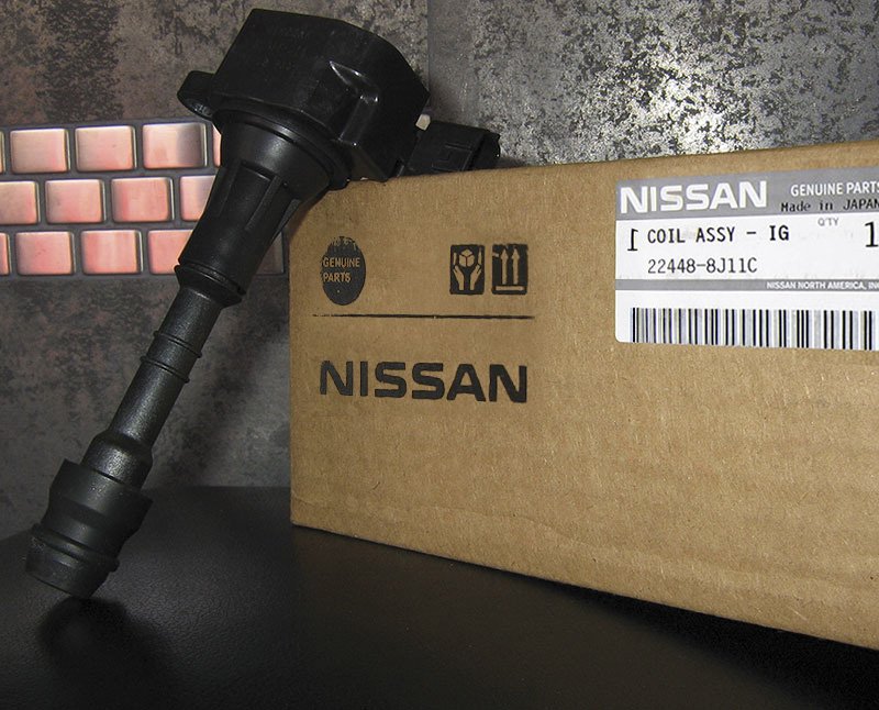
Aftermarket coils are prone to short life spans because their manufacturers reduce production costs for their power transistors, transformer quality, and insulator robustness. Do the job right the first time: replace ignition coils with Genuine Nissan products.


Thanks for the great information,keep up the good work.