
One racers’ trick is the use of a vacuum pump plumbed into the crankcase to lower crankcase pressure. There are a myriad of positive benefits and gains, some obvious, some not so obvious, and there are certainly a couple of precautions that you need to be aware of if you decide to use one on your application, so let’s take a look at them and how they might fit your program.
Reducing engine crankcase pressure improves external leak control, helps with ring sealing by increasing pressure drop across the ring pack and venting the area between the top and second ring more efficiently, improves crankcase pumping losses, has a positive effect on windage and oil contamination, and increases horsepower by aiding ring seal at higher rpm while allowing for thinner, lighter, lower-drag ring packages.
A lot of folks think that all of the horsepower gains made are just from running low tension ring packs and improving ring seal, but I think a good case can be made for the idea that if the piston normally “sees” a pressure of 100 psi on the top and a pressure of 14.7 or a touch more due to blowby on the bottom, then the total pressure drop across the piston is 85.3 psi.
Now, if we drop the crankcase pressure by 20 in. Hg, that’s about 10 pounds per square inch, and the pressure drop across the piston is now 95.3 psi. Since torque is simply cylinder pressure times the stroke (or lever), engine torque has to rise — and horsepower rises as well by as much as 50-60 horsepower on some applications! Where, exactly, the power increases come from is open to discussion, but the dynamometer and the race track don’t lie. Vacuum pump-equipped engines consistently produce more power on the dyno and lower ETs and higher mph at the track.
Racing-only solution
Reducing engine crankcase pressures and providing positive crankcase ventilation isn’t a new idea. It’s been around on street cars since the advent of the positive crankcase ventilation (PCV) system first launched in the early sixties, and with the Pan-Evac system that was used by many racers as far back as the early seventies that I can recall, and they may have been around before that. The first time I remember seeing it in person was on Grumpy Jenkins’s Vega out East at Cecil County or Atco when it was still a body in white (Navy uniform), but I seem to remember reading somewhere that Hedman Headers was an early leader in Pan-Evac.
The purpose of the PCV system isn’t really for performance. It replaced the old road draft tubes of the fifties and before that swept the crankcase by passing air over a taper-cut tube as the vehicle rolled down the road. The problem with that was it provided very minimal air flow through the crankcase, and if the oil breather was restricted or there was any significant amount of blow-by the system was simply overwhelmed. The result was dirty oil and sludge, often to the point where one of the recommended services became pulling the pan off and cleaning it periodically.
Because the system was passive and open to the atmosphere, the hot, noxious vapors poured out of the tube and contributed to photochemical smog, that nasty reddish haze that hung like a dome over the big cities in the bad old days. The PCV system is a metered vacuum leak attached to a valve cover designed for best operation during part throttle, and it works to keep crankcases much cleaner, and reduces HC pollution of the atmosphere by recycling blowby from the crankcase back into the intake for more-complete burning. Of course, under high load conditions, the PCV stops working altogether as engine vacuum drops to near zero.
A side benefit to running any sort of crankcase vacuum system is a reduction or elimination of engine oil leaks. Even PCV-equipped street cars often remain drip free for many years if the system is kept clean and operational. While under ideal conditions, the PCV system might make a few inches of vacuum in the crankcase at high manifold vacuum levels, racers quickly figured out that they needed a different approach to maintain pan evacuation under load.
The Pan-Evac system taps the exhaust system with a taper-cut tube long enough to reach into the exhaust collector and “sense” exhaust gas velocity and a check valve to maintain one-way flow. The exhaust gas velocity created a low pressure signal and when plumbed into the valve covers provided a very slight negative pressure in the crankcase. The downside to the design is that since the system is passive, it only creates a negative pressure of roughly one to two inches of vacuum on most engines, and that’s when some smart racer started using a belt-driven emissions air pump to mechanically pull a vacuum.
The issue with these converted systems was service life because those pumps weren’t meant to handle crankcase vapors and oil mist. Now, there are dedicated pumps made that are repairable and made from materials compatible with crankcase vapor.
 |
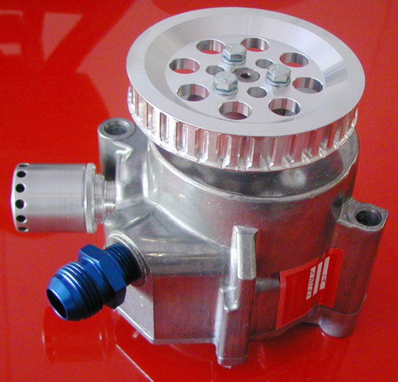 |
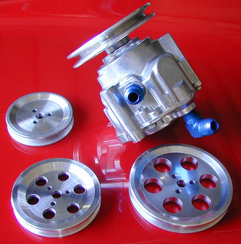
| Vacuum pumps are rated by SCFM air flow and are available in different sizes and configurations. The drive can be a standard Vee-belt, a Gilmer-type square-tooth, or a High-Torque-Drive belt, and different drive and driven pulleys are available to increase or decrease pump speed. Most pump builders recommend that you limit pump speeds to something under 6,000 pm at the pump. If you were wondering about the term “Gilmer” belt, it refers to one of the earliest makers of toothed belts, the L.H. Gilmer Co., which was acquired by Uniroyal in 1940 and later absorbed by Gates Rubber. It refers to a square- or trapezoidal-shaped toothed drive belt like those used on some of the earliest timing belt applications. Today, most toothed belts use a curvilinear-tooth or rounded-tooth, which has more contact surface area and is capable of transmitting more torque, hence the High-Torque Drive moniker. Virtually all of the racing timing belt systems I’ve seen use the rounded-tooth design, and to the best of my knowledge so do all the late model street engines out there that still use a rubber timing belt to drive their cams. Today, “Gilmer” is an archaic term, but still often used and understood to be the earlier square-tooth design by most people who frequently use that type of belt. | |
Belt or electric?
There are two options when it comes to engine vacuum pumps, mechanical belt-driven if you have room to mount it, and electric motor-driven if real estate is scarce and you need a remote option. The belt-driven pumps are available with different sized pulleys to limit drive pump speeds to around 6,000 rpm maximum and/or somewhere between 55-75% of engine speed. Again, this is an area where reading the directions is helpful.
Wire stiffened hose or braided stainless hose rated for vacuum can be used to plumb the pump suction to the engine and the pump discharge to the combination catch can and breather. Belts may be either standard Vee-type or Gilmer, depending on your application. The obvious advantage to the Gilmer drive is that it’s positive, and if the rate of acceleration for your engine is violent enough a Vee belt might slip or fail as it tries to overcome the inertia of the pump.
It’s a cautionary tale
The amount of engine vacuum you shoot for will depend on your oil pump type (wet sump or dry) and your performance goals. Most engine builders and vacuum pump suppliers recommend an upper limit of 15-16 in. Hg of vacuum for a wet sump Engine, and 20-22 in. Hg for a dry sump. Adjustable vacuum breaks are used to set the upper limit, and you’ll have to experiment to know what works best for your build. There can be too much vacuum in the crankcase, as we shall see next.
Some builders have postulated that the oil mist that lubes walls and pins falls out of suspension more quickly with too much vacuum, which they believe leads to lubrication and cooling shortfalls on the cylinder walls and pins.
I find it hard to believe that given the operating rpm of a typical racing engine and the voluminous amount of oil thrown off each rod pair through the side clearance that running high vacuum contributes much at all to any sort of pin or piston skirt lubrication issues… but I’ve been wrong before. A case MIGHT be made for the oil dropping out of windage more quickly, thus lessening the oil available to the bores given that part of the effect of removing air is a potential increase in oil movement (all objects fall at the same rate in a vacuum regardless of surface area), and that combined with a vacuum-induced increase in the density of the oil made possible by removing the air and leaving it mostly oil could have an effect I can’t envision. BUT that same removal of air and lowering of pressure would also result in a more dense oil droplet with theoretically longer droplet travel once it’s pitched off the crank — the outgoing travel away from the spinning crankshaft would be just as energetic if it departs up toward the bore as it would be if it were thrown back to the pan in a lower pressure atmosphere — so I’m left wondering if the high vacuum caused the issue, or if the higher accompanying engine speeds allowed by increased crankcase depression required a more robust pin or a coated pin, or a change in clearance to prevent failures and we just blamed the high vacuum levels. I guess in my mind, the oil is flying out of that rod pair all the way around the rotation plane and while we have kick-outs and screens below to strip away the oil as it rotates into the pan on the upper end, it’s still free to be thrown upward and outward onto the bore, skirt, and pin. Maybe someone can explain to me what I don’t know about this…
All this cogitating doesn’t change the fact that there were reported pin and piston issues when engine vacuum pumps were first used, but in my mind it’s more likely that those early problems were attributable to the higher engine speeds made possible by the pump and the fact that in those first versions the builders hadn’t adjusted their techniques to account for the higher engine speeds that were attained. Provisions can be made in the form of piston oilers (via a manifold built into the oil pan near the pan rail) used to spray oil up under the piston onto the pin, walls, and bottom of the piston head if you are a subscriber to the theory that high vacuums create oil shortages around the pins and bores.

Racing engine vacuum pumps require a bit of oil passing through them for lubrication. The earliest attempts at using smog air pumps as engine vacuum pumps failed in part because they were never designed to pull vacuum and only produced a usable vacuum when driven at speeds high enough to cause failure, and they weren’t designed to handle the oil that got ingested during operation. Racing pumps need to have a bit of oil flow to keep them alive and use the oil vapors and mist pulled through them for internal lubrication, but that requires a catch can with a breather system on it, which becomes one more thing you have to remember to check and do in between runs. Forgetting to drain your catch cans and oiling the track down will not win friends and influence people!
Pressure again

In most cases, mounting is simple and straightforward, although using terms like that when building a racing engine is inherently dangerous. Brackets, drive mandrels, and pulleys are available and usually you can mount the pump and align the belts without too much effort. If you’re running a blower, cam-driven fuel pump or other space-robbing components on the front of the engine can be spaced off the block and the pump-mounted facing rearward because the pumps can be driven in either direction. Just remember that the inlet and outlet often swap positions if run in reverse rotation — always refer to the literature supplied with the pump and read it completely before beginning your installation. In fact, I’ve learned through hard experience that you should do that with every single racing engine component — read it ALL first, then start mocking-up and building if you want to save yourself some time and pain. The hoses to the engine must be rated for vacuum. In this application, they use a wire-supported clear hose, but most stainless-steel braided hoses and most press-on or socketless hoses are also rated for some degree of vacuum. If you refer to your hose supplier’s catalog, you’ll see both a pressure and vacuum rating for the type and size of hose available. Again, read carefully — typically, the larger the hose inside diameter, the lower the vacuum it can handle. It’s all about wall strength and inside surface area.
On most engines there will be an oil pressure drop when the vacuum pump is installed. Why? Because we’re back to the idea of pressure drop across a fixed orifice. Volume supplied and the leak rate of that volume out of a fixed dimension sets the pressure. If you pull a 20 in. Hg vacuum with the pump, then you increase the pressure drop across the bearing clearance by roughly 10 psi — the oil is “pulled” from the bearing and the volume through the bearing increases which “acts” or “looks like” a larger clearance, and anyone who’s built an engine with larger clearances knows what that means to oil pressure.
You’re also messing around with the differential pressure that moves the oil from the pan into the suction of the pump. If you run deep vacuum in the pan, you run the risk of having less pressure in the pan than what is generated at the suction of the pump, and if that occurs the scavenging or pickup flow stalls. 16 in. Hg of vacuum on a wet sump engine is pretty close to the practical limit because that leaves a positive pressure in the pan of about six psi, which becomes the suction head available to move the oil into the negative pressure of the oil pickup.
There may also be an effect caused by the fact that you are now reading what should be an absolute pressure with an atmospheric gauge. An absolute pressure gauge reads 14.7 psi at rest in open atmosphere and zero at a perfect vacuum, whereas the typical atmospheric gauge reads zero psi at rest. In my previous life, I worked with gauges marked as PSIA or PSIG, which indicated “absolute” or “gauge,” which is atmospheric. A PSIG gauge assumes that the pressure reading is taken from something near 14.7 psi as the starting point. If you think about it, the total pressure drop is really pretty much the same. Just remember that pressure is the result of volume and the restriction that that volume is moves through; the same volume through a smaller hole will show more pressure on a gauge attached to the pump. Anything that increases or decreases the flow rate through and out of the bearing clearance will have an effect on pressure readings.
There are limits

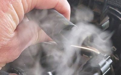
Location of the vacuum port should be high up and forward to minimize oil carry out from the engine, and the driver’s side valve cover is a good choice. If you think about the dynamic forces present on a race car, either a drag or track, the oil will be shoved back or to the outside, and locating the suction of the pump high and forward keeps the suction out of most of the wet flow. You can size the catch can for your application, using a larger tank with better oil separation and multiple breathers if track rules allow a pump on a duration racing engine. Something to remember about running engine vacuum: The better the mechanical sealing, the lower the unnecessary flow created by pulling outside air through the gaskets and seals. High flow rates might cause a lot of oil carry-out and what would be preferable is to make sure the engine is tightly sealed mechanically during the build so that the only flow you have to manage is whatever blowby flow is produced by the engine. If you have access to an evaporative emissions system smoke machine, it’s a great tool to use to check and verify your engine sealing efforts before dropping the engine in the car.
Because a vacuum pump is capable of pulling much more vacuum than the engine would like, it’s important to design the system with a vacuum break in place. The same companies that make vacuum pumps also make fully-adjustable vacuum breaks in different configurations and threaded male sizes. As a starting point, most builders will recommend limiting the vacuum on a wet sump engine to something around 16 in. Hg and 22 in. Hg on a dry sump, although there are some racers running as much vacuum as they can get on wet sump applications — as much as 23-24in. Hg has been reported on some applications. How much is right for you application is something you’ll have to select for yourself by slowing increasing crankcase vacuum while monitoring your pressure gauge for signs of suction side flow reduction, which often shows up as oil pressure gauge fluctuations.
Finally
Vacuum has to be managed because there are physical limits to how much is safe to run. Vacuum breaks or vacuum regulators are used to set the maximum vacuum at levels that don’t create suction head pressure problems for the oil pump. Safe levels are in the 12-16 in. Hg for a wet sump engine, and in the 18-22 in. Hg range for a dry sump engine, but again, this is all subject to testing and validation for your application. If you get a wildly-fluctuating oil pressure, you’re running too much vacuum for the oil pump to handle. Oil pressure is expected to drop by roughly your engine vacuum in inches of mercury divided by two, so if you normally run 70 psi and you introduce a twenty-inch vacuum in the crankcase, twenty divided by two is 10 and your oil pressure should be about 60 psi, but it must be steady on the gauge or else you’ll need to reduce engine vacuum. At the end of the day, it will be your engine bearing wear that will tell you everything you need to know about your oil delivery system, so look at it often, keep records at the end of each season, and keep the bearings in order as part of your regular PM program as a means of monitoring engine health.

Vacuum has to be managed because there are physical limits to how much is safe to run. Vacuum breaks or vacuum regulators are used to set the maximum vacuum at levels that don’t create suction head pressure problems for the oil pump. Safe levels are in the 12-16 in. Hg for a wet-sump engine, and in the 18-22 in. Hg range for a dry-sump engine, but, again, this is all subject to testing and validation for your application. If you get a wildly-fluctuating oil pressure, you’re running too much vacuum for the oil pump to handle. Oil pressure is expected to drop by roughly your engine vacuum in inches of mercury divided by two, so if you normally run 70 psi and you introduce a twenty-inch vacuum in the crankcase, twenty divided by two is 10 and your oil pressure should be about 60 psi now, but it must be steady on the gauge or else you’ll need to reduce engine vacuum. At the end of the day, it will be your engine bearing wear that will tell the tale.

0 Comments