

Feedback we received from our recent survey showed an interest in seeing articles that are based on case studies – actual vehicles with a specific drivability problem that arrive at a shop’s doorstep. So this issue includes not one, but two case studies as experienced by our “tag-team” tech gurus, Augie Ferron and Eric Dibner. Read on and then let us know what you think.
One part of this article and investigation began as “is this how it really works?” The second part was an attempt to keep it simple. The vehicle being tested and interrogated is a 2007 BMW X3 3.0i. The curiosity in the beginning was “What can I see at the data link we are all so familiar with?”
My interest and initial curiosity was to see how the scan tool functions at the DLC. If the homework wasn’t completed, some mistakes and incorrect assumptions can be created when there is a lack of understanding of this BMW network and its “marriage by convenience.” The best place to start is with a detailed schematic and grasping the interconnectivity within this network and with this specific model. In this article (Part 1) we will view the inter-relationship between the scan tool and the network. As for Part 2, using a CAN and or K analyzer will offer a deeper insight.
Keep it simple – or at least try
This BMW had no real issues to speak of, no problems so we decided to look at this vehicle with the simplest and most portable tools possible. Everything was accomplished without creating any faults or damage.
- Tools used – Keeping it simple and having choices
- Tested with BMW Rheingold with K + DCAN Cable (Laptop)
- Tested with Launch EasyDiag (Android Tablet with BMW Application)
- AR Oscilloscope (2 channel Bluetooth
with Android Tablet or Laptop) - OTC DLC breakout box
- 90 amp floating power supply
- A current and specific Data Lines schematic
One word of caution: Any and all KOEO diagnostics MUST have a clean low A/C ripple power supply attached to the electrical system to maintain the required voltage (current) supply, keeping the vehicle alive and stable.
Connectivity and how this was done

Rather than “jump” pins 7 and 8 with banana plugs on the break-out box, a switch is preferred to switch diagnosis pins from the new to older models that require pin 8. Closing the switch now makes pins 7 and 8 parallel.
I will assume many of us will use a 4 to 8 channel oscilloscope to view the “K,” “CAN,” or “LIN” BUS signals as they pass throughout the network. The choice was more of an experiment to use a miniature 2 channel battery-operated and Bluetooth-connected oscilloscope module. The requirements were to be: uncomplicated, quick, and effective, with a simplified setup. Another requirement was that the oscilloscope must work with either an Android or a laptop connection. Step 1 was to gather an entire scan.
The EasyDiag was the first scan tool used because of portability, and it worked flawlessly. Rheingold was used because of the network viewing layout within the software. Both software platforms and the Autel Pro tablet offered similar results.

The mini switch used can be purchased at any electronics outlet. Solder the two wires to pins 7 and 8, then the switch and mark it.

With the vehicle connected via USB cable, this image describes the entire network this vehicle was designed with, including connectivity and faults.
The K + DCAN Cable that was used is the one with the green circuit board. The white ones don’t seem work within this specific application. With this simple cable however, a switch was added to connect pins 7 and 8 together on the DLC.
 and pins 6 and 14 (CAN-BUS).")
To view the actual network activity, a break-out box is used in between the DLC and diagnostic cable. Pay close attention to the LEDs when a diagnosis is performed on the entire vehicle or on a specific controller. My interest was pin 8 (K-BUS) and pins 6 and 14 (CAN-BUS).
In the view with the DLC breakout, there is a banana plug attached to pin 4 and used as the oscilloscope ground. Pin 8 is connected for the K-BUS and this connection will measure the K-BUS activity on the oscilloscope during diagnosis.
Things you should know and what you’re looking at
This specific BMW has three separate networks. All three are operating at different protocols, different levels of speed, and different data sharing abilities. These three networks also operate independently or are co-dependent of each other. This is a marriage of protocol and language within three separate systems. All of those systems do get along with no complaints and no conflicts.
Note: The network not visible is the LIN network.
So what does all this mean?
Read the schematic and view the scan tool. We need to know what the networks are and how they behave. It’s when we have a problem with a controller(s), that this article will help when there is “no connectivity” and also what the messages look like when the scan tool is connected to the controller and/or the network. When there is a connectivity problem or issue, a data line schematic and understanding how the controllers are connected will aid in a proper diagnosis.
Types of data busses:
The K-BUS is a method of bi-directional control that will also display the current state of a data group. The K-BUS can also interconnect with other controllers and share information as required by the program written into the controller processor.
The K-BUS is a single wire connection with a data transfer speed of approximately 9.6 kbps. The only activity that should be seen is when the scan tool accesses the K-BUS and connects to a controller. The K-BUS only operates at nominal battery voltage, therefore the battery must be in good condition utilizing a clean power supply at all times.
HINT 1: It only takes one K-BUS, CAN-BUS, or LIN-BUS controller or connection that is “BUS Damaged” via short to ground, short to positive, or suffering internal controller damage, to take the entire BUS down with no possible diagnosis.
HINT 2: In the glove box area are the K-BUS terminating connections, and opening one BUS connection at a time will help narrow the “culprit” via scan tool or multi-meter. Read the schematic and remember that this model at pin 8 is a White/Violet (K-BUS) wire to specific controllers BUT splits the connections at the instrument cluster as White/Red/Yellow. The instrument cluster becomes the gateway for the K-BUS and CAN-BUS.
The CAN-BUS network operates far differently from the K-BUS. This network shares data between the connected controllers with a twisted pair of wires at speeds up to 100 kbps. The CAN-BUS network transmits data within the entire structure, but only the controllers that require that data will accept the data. The rest is rejected.
This network also is a method of bi-directional control and will display the current state of a controller. It is no different than the K-BUS network, but it is possible to diagnose IF the connected K-BUS is still operational within a controller that uses the K-BUS for diagnosis.
The LIN BUS (Local Interconnect Network) is a low cost network that reduces the BUS load of the CAN network. The LIN BUS is a low-speed, single-wire serial data BUS. This network can be called a “slave” network that operates, controls, and maintains functions of non-safety, non-critical control units such as mirrors, heater motors, wiper motors, etc. via the CAN “Master” network. In this model, LIN is connected to both mirrors and the Driver Door Module via General Module.
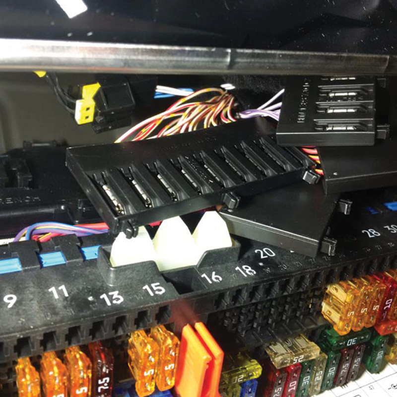
Following the schematic and this image clearly indicates the multiple connections that are easy to find and opened one at a time for testing or measured with a meter/oscilloscope.
So what do the BUS connections look like?
Using the schematic and looking at the images, we can now see the layout and colored wiring found just above the fuse panel that resides behind the glove box.
Repeating these steps with a scan or direct to the DME and EGS while attached to pins 6 and 14, the oscilloscope reads the CAN data produced by the connection to either DME or EGS.
The link provided offers a full view of the schematic used and a short video with Rheingold. The video will offer an identification of the controller addresses BWM uses during the scan process.

The “chatter” produced between the scan tool and either DME or EGS will be in view and will change when operating the scan tool. The CAN-BUS message will also change when engine or transmission parameters change.

When diagnosing other controllers that are NOT using the CAN-BUS, this time pin 8 will be active. The same message changes will occur on the K-BUS or LIN-BUS with scan tool activity or controller parameter changes.

0 Comments