
- 2009 Volkswagen Tiguan
- 2.0L TFSI Automatic Transmission AWD
- Crankshaft seal “unglued itself”
This article is specific to an oil leak that developed very quickly. This vehicle required a flat bed to be returned to the city. The oil consumption within a 4 hour drive out of the city was approximately 3 quarts.
Inspection proved the oil leak came from the crankshaft flange seal between the engine block and torque converter drive plate.
All research dictates specific bolts and seals that must be replaced when the transmission is removed for inspection. Any seal that is removed or disturbed must be replaced. Scan and save the entire autoscan. Adaptations will be required on the first start-up to prepare for delivery to the vehicle owner. This procedure will apply to all CCTA TFSI engines with or without 4WD.
Special tools used:
- Ross-Tech VCDS
- Smoke Pro smoke machine
- Engine bar support
- Transmission jack and strap
- Torque wrenches
- Transmission drive plate holder
- Pressurized transmission fill reservoir or equivalent tool
- Camera
Note: Be well prepared when attempting this type of repair and note the seals/bolts with replacement parts that must be available before and during disassembly and reassembly. Capture the entire initial scan and have a copy of the PR code to accurately identify the model being worked on and in conjunction with installed factory equipment. Print and read the repair instructions first.
Upon inspection on the lift, clean all areas of the oil leak and capture the contaminants for proper disposal. In this specific case, a smoke machine was used to identify the leak between the engine block and transaxle. The smoke machine was attached to the dipstick tube for the inspection.
When the operation is confirmed and the repair authorized, remove the battery, tray, upper air inlet tubes and hardware to expose the transmission with upper mount.
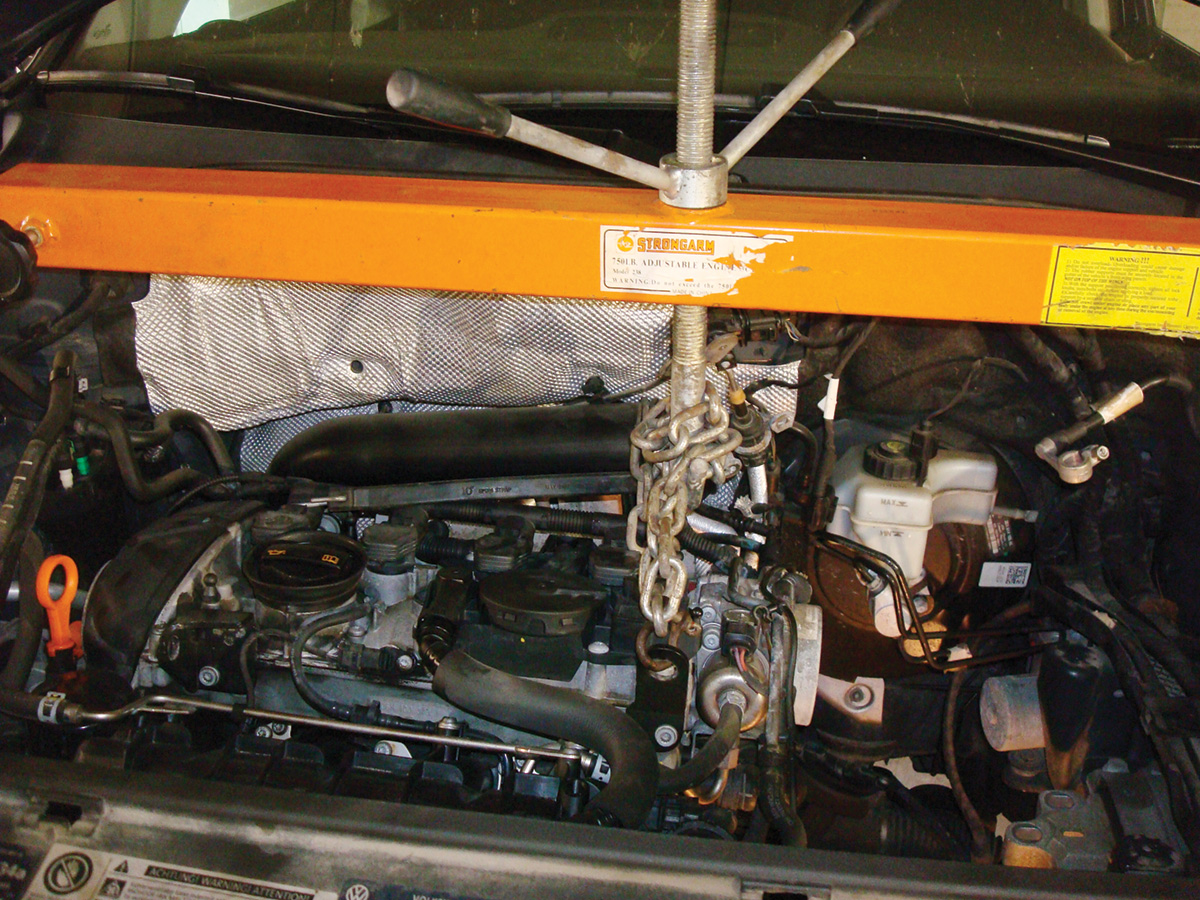
Prepare this model by loosening the axle bolts (one-time use), remove the front wheels, LF inner plastic liner, and remaining lower air induction tubes. Remember to replace all disturbed seals, o-rings or one-time use bolts. Prepare a safe and correctly fitting engine lift bar onto the fenders with rubber pads/insulators. The illustration indicates the correct position.
Disconnect the ball joints and link pins on both sides, remove both drive axles. Clean and lightly lubricate the splines before reassembly. With the LF inner liner removed, inspect/prepare the transmission jack angle and height when ready for final removal.
Remove the rear drive shaft from the bevel gear flange and clean that flange surface and drive shaft surface.
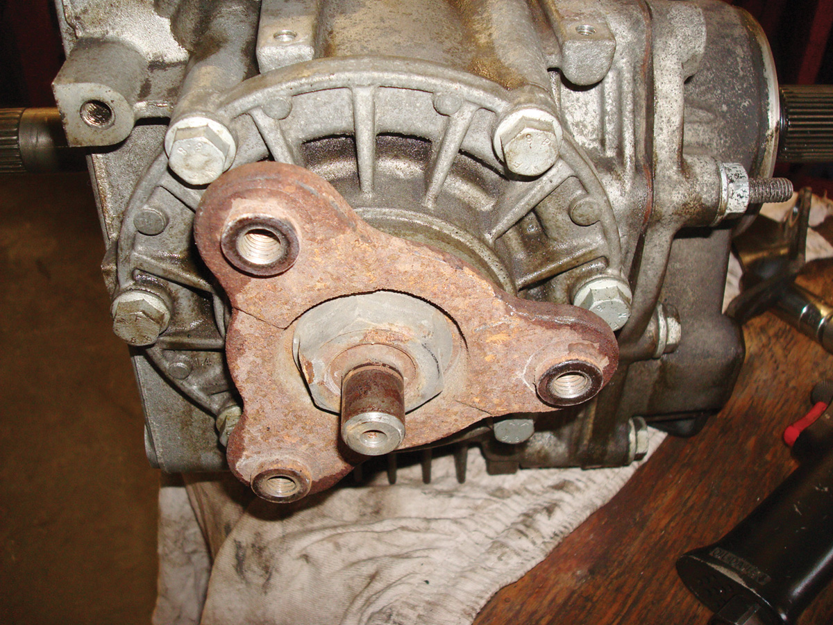
Remove the transmission center support mount attached to the subframe. Access the bevel gear bolts and notice their lengths. Remove the bevel gear assembly. At times, and depending on the model, a wedge is required to gently tilt the engine/transmission assembly for ease of access. Remove the wedge when the transmission is ready for removal.


Remember that both mounts will “hang” the assembly for access and safety. Notice the next image and placement of the two inner bolts. There will be a high degree of appreciation when those bolts are in position during reassembly. Ensure the surfaces of the bevel gear and transmission are cleaned before assembly.
Gently clean off any extra debris and oil. Wipe down all bevel gear mating surfaces, shafts and mounts. With the bevel gear removed, align the first torque converter nut using the crankshaft bolt, turning in the direction of engine rotation.
Mark one torque converter stud and remove the remaining nuts while turning the crankshaft in direction of rotation.
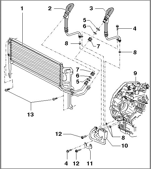
Disconnect the transmission cooler lines at the transmission aluminum block and plug both the aluminum block and lines to prevent any fluid leakage and injection of debris (plastic caps work well).
Note: To access some plumbing and fasteners, remove the remaining induction tube from the throttle body to the intercooler. Pay attention to the harness connecting the pressure sensor at the induction tube. Disconnect the transmission harness and shift cable. Make sure all electrical connections remain clean for reassembly.
Clean that surface and the ground stud before assembly.
With the correct amount of support, the transmission mount, cables, harnesses and grounds can be removed. Remove the mount as illustrated. Angle the transmission with the engine lift to clear the body with the transmission jack in unison. Hold the engine in that position with the support bar for correct alignment.
Remove all transmission bolts (except for one) with the transmission stand in place and transmission strapped to the jack. Check all clearances. Remove the last bolt when assured of a simple maneuver with a clean floor to easily roll the jack safely. Maintain the alignment for assembly.
Notice the white painted stud on the converter. Do not remove or disturb the torque converter. Do find a way to gently hold the converter in position. I used a wooden rod with spacer attached with bolts to the bell housing. This will ensure the correct position if the transmission needs to be rolled or moved to another position. If for any reason the torque converter is removed, the seal must be replaced.
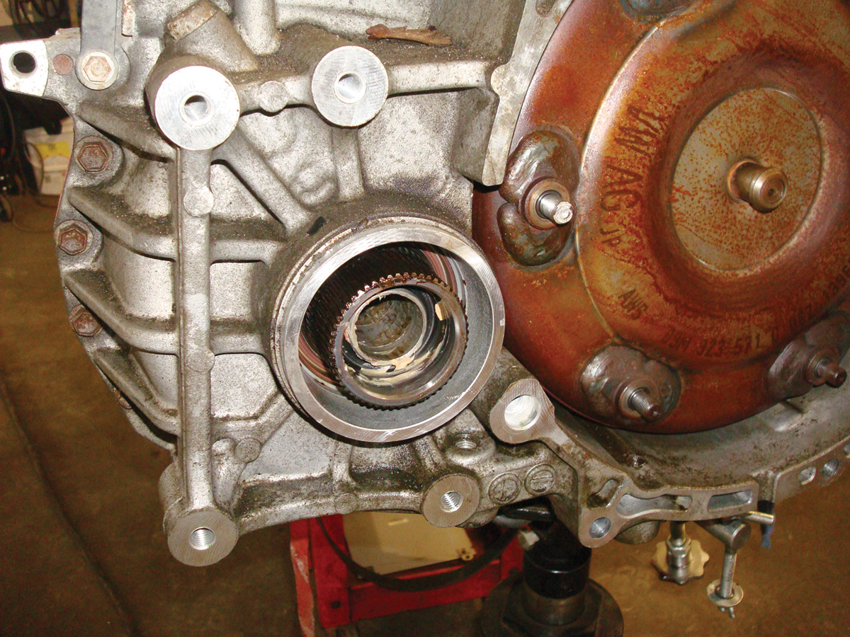
Clean the splines on the transmission differential side and do not disturb the inner seal. Do not use harsh chemicals. Apply a light weight, clean wheel bearing grease in a film on the spline and bevel gear surface. Clean all traces of oil around the torque converter and bell housing.
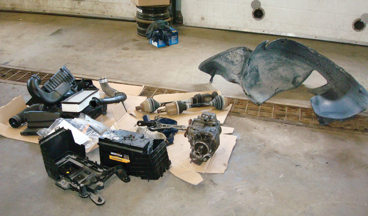
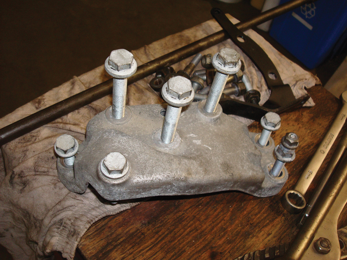
These are the components removed that indicate some floor space required for storage. Magnetic trays are a great way to keep the mounting hardware in a relative order. On one side of the inner wheel well, lots of leaves, twigs and other debris were noticed. Remove the opposite liner and clean out both sides. The vehicle owner will appreciate the “fermenting” debris removal.
Consider this as part of “maintenance” when debris does enter the area between the body and inner fender liners. You will be surprised when viewing the amount of collected debris.
As mentioned before, the seals number 8 need to be replaced because those seals were inserted to aluminum block number 10. Clean that area very well before removal and make sure the tubes and block are absolutely clean before assembly. The connections will leak with old rings and compromised sealing surfaces. This option was chosen to keep the transmission removal compact and lessen the chances for other transmission cooler line damage at the quick connects. Take great care not to bend or pinch the transmission cooler lines.
Once the transmission drive plate is removed (mark it as well) and the crankshaft flange seal unbolted from the engine block, prepare/clean the block of old sealant, oil and any debris. Look at the original seal. It has “unglued itself.”
Note: The entire block surface must be clean with no oil residue. The seal (PTFE) surface and crank surface must not have any oil present.
The crankshaft area should be cleaned/polished slightly with extremely fine pads similar to Scotchbrite.
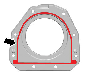
Apply the sealant to the new sealing flange similar to that shown in the image. Ensure that the engine block surface is clean and dry or the sealant will not cure correctly and will eventually allow oil to migrate. It will take substantial force (with the supplied tool) to gently push the flange seal squarely onto the crankshaft to meet the prepared engine block surface. Use new bolts only.
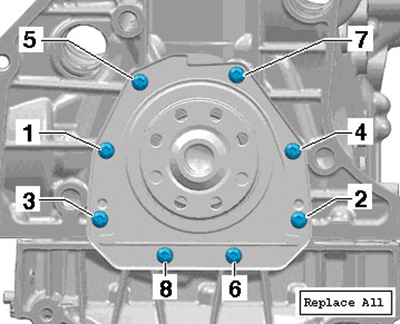
Note: do not rotate the seal or the crankshaft for a minimum of one hour before and after final assembly with torque setup.

The PTFE seal requires time to set up. Use the printed/repair information/specifications to torque using the proper sequence/value for the model you are working on.
Replace the oil separator on top of the valve cover. The upper one is the most common one to fail. The lower vent system rarely fails but when this model is due for the intake cleaning, the lower one will be replaced at that time.
Assemble and torque all components in the reverse order following the repair information. Change the oil and filter with the correct oil rating and quality oil filter. Run the vehicle for a few moments, check for leaks but do not run the engine hot at this time.
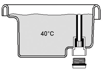
If this model has high mileage, this is a very good time to replace the transaxle fluid by removing the plastic port above the fill/inspection plug. Capture all the fluid and calculate the amount of fluid removed. When complete, re-insert the plastic port and inject 75 percent of the measured new fluid and attach the fill/inspection plug lightly.
Prepare VCDS, start the vehicle and enter Transmission Electronics. Start this test at ambient temperature. Have enough of the correct transmission oil on hand. Pay attention to the transmission fluid temperature within VCDS during the warming phase and with the fill/inspection plug removed. Watch the spill port and VDS at idle only. The measured value for temperature is group 006, field 1 for ATF Temperature sensor G93.
The “filled” test is as follows:
- Apply the forward and reverse gears a few times and test in Park with the plug in place.
- At idle and the plug removed with VCDS:
- Not dripping = Requires topping up at the required temperature.
- Dripping = Full at the required temperature. Make sure a new gasket is available and torque the plug. Check for leaks.
These are the steps in the correct order to clear the faults on startup and preparing for a road test with VCDS.
Make sure a clean and stable power supply is attached to the battery – KOEO
A. Completely scan the vehicle and clear all faults – save that scan.
B. Set up throttle body adaptations at the ECM (basic settings).
C. Set the clock and radio.
D. Reset the HVAC (basic settings).
E. Apply the TPMS re-learn (button on console) and re-set all tire pressures.
F. Re-set all the windows for “One trip.” Cycle each window three times up and down, on the fourth cycle, hold the switch(s) up for 5 seconds.
Remove and store the power supply, start the vehicle.
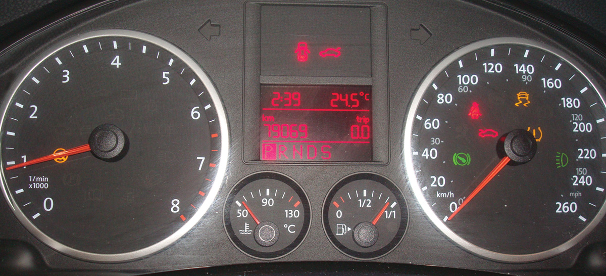
G. At operating temperature and with all fluids topped up, road test above 50 kmh (30 mph) for approximately 15 to 20 minutes. Perform a few figure “8s” in safe and open space, apply the ABS once in the straight ahead position and stop the vehicle. Cycle the key once to re-start.
H. Check faults again. If any faults return for ABS or TPMS, begin the test again.
Perform the final re-check for any leaks, routing of plumbing/electrical connections and final assembly. The final autoscan should have no faults recorded unless the radio does not have a Sirius XM subscription.
Attach the belly pan and ensure wheel torque.
Parts used:
- New dealer or OEM equivalent crankshaft flange seal
- New dealer or OEM equivalent crankshaft flange seal bolts
- OEM equivalent sealer or “the Right Stuff”
- New dealer or OEM equivalent transmission cooler tube seals
- Dealer or OEM equivalent transmission fluid
- New dealer or OEM equivalent bolts and drain plug/inspection washers
- New dealer or equivalent axle bolts
- New dealer or OEM equivalent oil separator (top)
- New dealer or OEM equivalent oil separator (bottom) if required.
Remember: Search for all available TSBs and Dealer Campaigns associated with the vehicle.
Download PDF


0 Comments