

These clever devices come in a variety of flavors, all in the interest of optimizing engine performance, fuel economy, and emission control. Understanding how they work and how they wear out will assure that they report accurate information to the ECM.
A gasoline engine requires 14.7 kilograms of air for each kilogram of gasoline in order to burn the fuel completely. This 14.7:1 air/fuel mixture is called a stoichiometric ratio and is the holy grail of engine management software and control modules. A tendency to operate on either side of that target number results in lower volumetric efficiency, which leads to reduced engine performance. If there is less air, the mixture is too rich, and some of the fuel cannot be burned. If there is less fuel, the mixture is lean, and the engine does not develop as much power as intended from each piston stroke.
In addition to performance problems, lower volumetric efficiency results in increased potential for emission of harmful substances, including carbon monoxide (CO), unburned hydrocarbons (HC), and oxides of nitrogen (NOx). The catalytic converter takes these three major byproducts of incomplete or unbalanced combustion and converts them into substances that do not contribute to air pollution.
The catalytic converter is most efficient at reducing HC, CO, and NOx when the air/fuel mixture is at or near the stoichiometric ratio of 14.7:1. However, different operating conditions require variations from the stoichiometric ratio. During cold start and engine warm-up, fuel condenses on cool cylinder surfaces, creating a lean condition. The engine control module (ECM) adds extra fuel to enrich the mixture. Similarly, the ECM enriches the mixture under full throttle conditions to provide more power.
Under idling conditions, the engine operates at the stoichiometric ratio. At part throttle, where the engine operates most often, a slightly lean mixture provides good fuel economy.
While transitioning from closed to open throttle, a lean condition occurs naturally. To avoid hesitation or lean surge during that transition, the ECM quickly richens the mixture.
Once the ECM issues commands to adjust the air/fuel mixture, it looks for feedback from oxygen sensors to confirm that its instructions had the intended result. Sensors before the catalytic converter measure and report to the ECM the content of the exhaust gases coming out of the combustion chambers. Post-cat oxygen sensors send data on whether or not the converter was able to successfully bring the three harmful gases – CO, HC, and NOx – within limits mandated by the Environmental Protection Agency (EPA) and by local/state regulatory bodies.
Three major categories of oxygen sensors

Air/fuel mixture data comes to the ECM in the form of voltage or current, depending on the type of oxygen sensor. There are many different types of oxygen sensors, from the earliest unheated, single wire, chassis-grounded sensor to modern multi-wire wideband sensors with built-in ground and heater technologies. Most fall into one of three major categories of oxygen sensors.
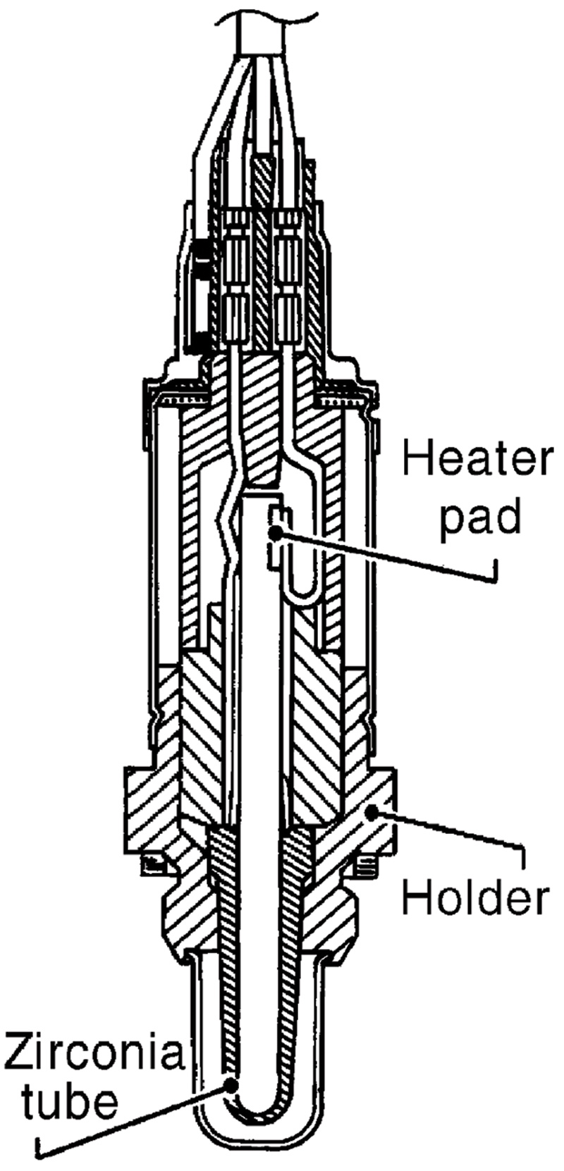
The original oxygen sensor design features a zirconium dioxide ceramic element in a thimble-shaped construction. Exhaust gas flows along the outside of the thimble, while the interior is filled with air from the atmosphere. Atmospheric air contains about 21 percent oxygen. It serves as a reference against which the concentration of oxygen ions in the exhaust gas (approximately 0.3-3.0 percent) can be compared.
The ceramic element (called a “Nernst” cell) separates the exhaust gases from atmospheric (reference) air. But when heated to at least 350 degrees C (660 degrees F), the ceramic element becomes permeable to oxygen ions. As oxygen ions travel through the ceramic barrier, the change in oxygen content from one side to the other generates a voltage. If oxygen content in the exhaust gas is close to 3 percent (lean mixture), a voltage of 0.1 V is produced. An oxygen content of closer to or under 1 percent (rich mixture) produces a voltage of 0.9 V.
When the oxygen content in the exhaust is at the ideal stoichiometric ratio, the standard oxygen sensor produces 4.5 volts, in the middle of the range. Outside of a narrow band around that 4.5 V mid range, the standard oxygen sensor is not accurate in its measurements. For this reason, it is called a “narrow band” sensor. Instead of reporting an exact voltage when the mixture deviates from stoichiometric, the narrow band oxygen sensor is considered accurate only as a directional high or low indication. It switches back and forth approximately once per second from the low of 0.1 V to the high of 0.9 volts. A change as small as from 0.1 percent to 2.0 percent oxygen entering the exhaust stream causes the voltage signal to the ECM to switch from rich (more voltage) to lean (less voltage).
A second type of oxygen sensor features a titania rather than zirconia element. Unlike the traditional zirconia oxygen sensor which generates voltage as the air/fuel mixture goes from rich to lean and vice versa, a titania sensor cannot create its own voltage. Instead of the sensor using reference (atmospheric) air, the ECM supplies a base reference voltage to the titania sensor, then monitors the voltage changes in the sensor as the air/fuel ratio in the exhaust stream changes.
Like conventional narrow band sensors, titania oxygen sensors switch between high and low voltages. When the mixture is rich, resistance in a titania sensor will be low and the voltage signal will be close to 1.0 V. When the mixture is lean, resistance increases and the voltage signal falls to about 0.1 V.
Because they did not need reference air, titania sensors had no outside air ports in their housing to worry about becoming clogged with road debris. They offered a faster warm-up time than traditional zirconia sensors. Titania sensors could work at lower temperatures, allowing them to be located further downstream from the engine. They also would not cool down at idle and stop sending a voltage signal to the ECM, as would an unheated zirconia sensor.
Nissan used titania sensors from the mid-1980s to the mid-1990s on Maxima, Sentra, 300ZX, Stanza 4WD wagons, and Nissan D21 trucks. On newer models, the company no longer uses titania sensors.
Both the traditional zirconia and titania oxygen sensors are called “narrow band” because, while they tell the ECM whether the mixture is rich or lean, they cannot give enough detail to report how rich or lean.
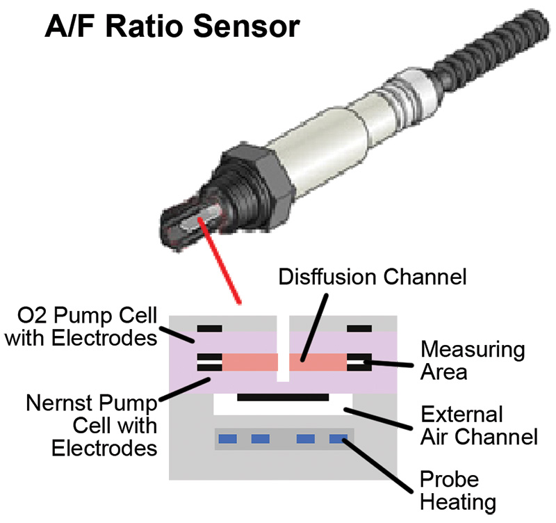
The third major type of oxygen sensor is the modern zirconia-based air/fuel (A/F) ratio sensor. It outputs a continuous voltage signal that varies directly with oxygen content in the exhaust. The A/F sensor reports the exhaust proportions of fuel and air throughout the entire range, from almost no leftover oxygen to near zero remaining unburned hydrocarbons. It accurately measures a much wider range of fuel mixtures than the conventional narrow band sensor – from as low as 12.5:1 up to 19:1, and so has earned the nickname “wideband” sensor.
How does it accomplish its magic? The A/F sensor “pumps” oxygen ions through the zirconia element from its positive to its negative electrode and back at just the right rate of flow to maintain a Lambda of 1, or 450 mV, on the electrode that interacts with incoming exhaust. The polarity and level of current required to pump enough O2 ions to restore Lambda inside the A/F sensor is then reported to the ECM, which translates it to fuel injector pulse width commands to achieve the 14.7:1 ratio in the actual air/fuel mixture.
Note that the A/F sensor outputs a current, not a voltage. The current is converted to voltage inside the ECM. Algorithms in the ECM use the voltage number to determine the exact amount of injector pulse width adjustment needed to bring the air/fuel mixture back to stoichiometric. The A/F oxygen sensor effectively contains an internal small scale model of the vehicle’s real-world closed loop air/fuel mixture control system.
A wideband sensor also updates faster (less than 100 milliseconds, or ten times per second) than narrow band zirconia and titania oxygen sensors. This leads to better fuel economy by allowing more mixture adjustments to be handled quickly by short term fuel trim (STFT) rather than needing to make long term fuel trim (LTFT) changes. Due both to its wider accuracy range and its faster response time, the wideband A/F oxygen sensor allows the ECM to make adjustments to the air/fuel mixture with greater precision and efficiency.
A/F sensors are typically located before the catalytic converter, while traditional narrow band oxygen sensors are positioned after the cat. The A/F sensor provides input that the ECM uses to make fuel trim adjustment decisions. The ECM uses measurements from the narrow band oxygen sensors in their post-cat locations to determine whether its fuel trim adjustments have brought the mixture back to or near stoichiometric. Nissan began transitioning from narrow band oxygen sensors to A/F (wideband) sensors with selected model year 2000 vehicles. All 2005 and newer Nissan models use A/F sensors for pre-cat measurements.
Not swappable
Because they look similar in construction from the outside, you have to be careful not to install a narrow band oxygen sensor in a vehicle that calls for a wideband unit. At minimum, this mistake will immediately reduce the information reported to the ECM to simply whether the exhaust gas coming into the catalytic converter is rich or lean. The ECM will not know the precise fuel injector pulse width adjustment needed to return the air/fuel mixture to stoichiometric in the shortest amount of time.
Conventional versus A/F sensor heater operation
The earliest versions of zirconium oxygen sensors were unheated. That required them to be located close to the combustion chambers so they could warm up quickly during cold starts. Proximity to high engine heat led to the early demise of many unheated oxygen sensors, so manufacturers developed new versions with a built-in heating element.
The heater is activated by the ECM based on engine speed, engine coolant temperature, and intake air volume inputs. The heaters in conventional zirconia oxygen sensors are commanded on at startup and at engine speeds below 3,600 rpm, and off at speeds above 3,600 rpm.
The heating element in an A/F sensor is handled differently. Unlike the voltage signal from conventional oxygen sensors, the A/F sensor outputs current to the ECM. Because current is affected by resistance and resistance is sensitive to temperature, the A/F sensor’s temperature must be kept constant in order to generate a consistently accurate signal.
The A/F sensor must be heated to approximately 650 degrees C (1,200 degrees F), twice the temperature of conventional narrow band sensors, to operate effectively. Battery voltage is supplied through a relay and fuse combination. The heater’s ground circuit is controlled by the ECM. The A/F sensor’s heater ground circuit is pulse width-modulated to keep sensor temperature constant in spite of rapidly fluctuating exhaust gas temperatures.
Nissan’s oxygen sensor heater trouble code detection logic is pretty robust. It will set trouble codes if the heater circuit voltage signal is too low (P0031 for A/F sensor 1, P0037 for HO2S2) or too high (P0032 for A/F R sensor 1, P0038 for HO2S2). It will set P0043 or P0044, respectively, if a third post-cat oxygen sensor (HO2S3) is installed and experiencing the same conditions.
The cause of a heater circuit problem could be an open circuit, short to power or short to ground, depending on whether the circuit is positively or negatively controlled. A less likely cause could be a faulty ECM not commanding the heater on. It may be complicated to find because, if an A/F heater is running very high voltage, the ECM may shut it down to prevent damage to the computer’s electronics.
Checking the amperage of the sensor’s heater circuit may confirm that there is a problem, but it cannot tell you the source of the fault. One effective quick and dirty test to confirm whether or not the ECM is functioning properly to send activation commands to the heater involves use of a small light bulb. Unplug the sensor’s heater harness and connect a bulb and socket in place of the sensor. Clear the codes and turn off the MIL, then turn on the ignition switch. If the circuit has power and the ECM is sending commands to the heater, the bulb will light up or blink.
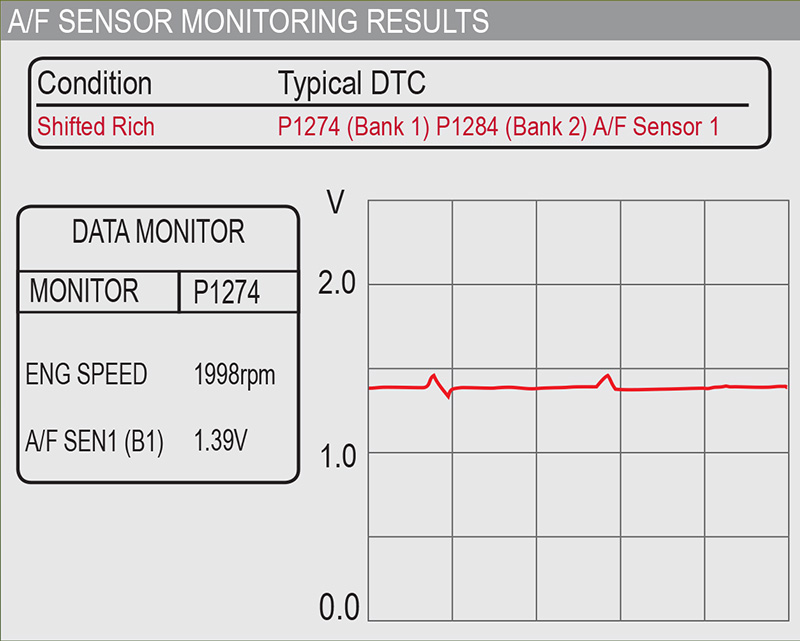
A/F sensor shifts rich or lean
The A/F sensor readings should fluctuate around 1.5 V when operating normally. Even a slight shift below or above the specified voltage could represent a shift to a richer or leaner mixture than desired. If the A/F signal shifts to the rich (<1.5 V) or the lean (>1.5 V) side, it could be caused by a malfunction in the sensor or its heater circuit. Before condemning the sensor, always check that the circuit indicated by any trouble code is receiving power and is properly grounded.
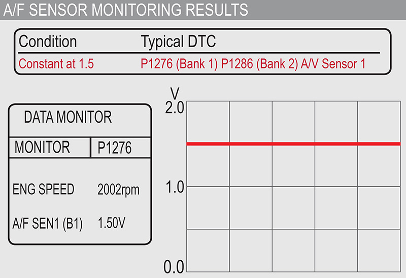
A/F sensor not fluctuating
If the A/F sensor is not fluctuating, even if it is constant at 1.5 V, there is likely an open or shorted circuit. Check the sensor’s harness or connector. Do the same if the sensor is constant high at 5 V or straight-line low at 0 V.
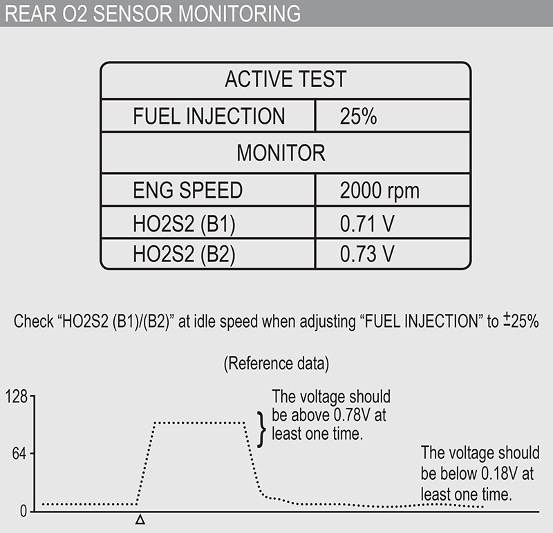
Rear oxygen sensor output
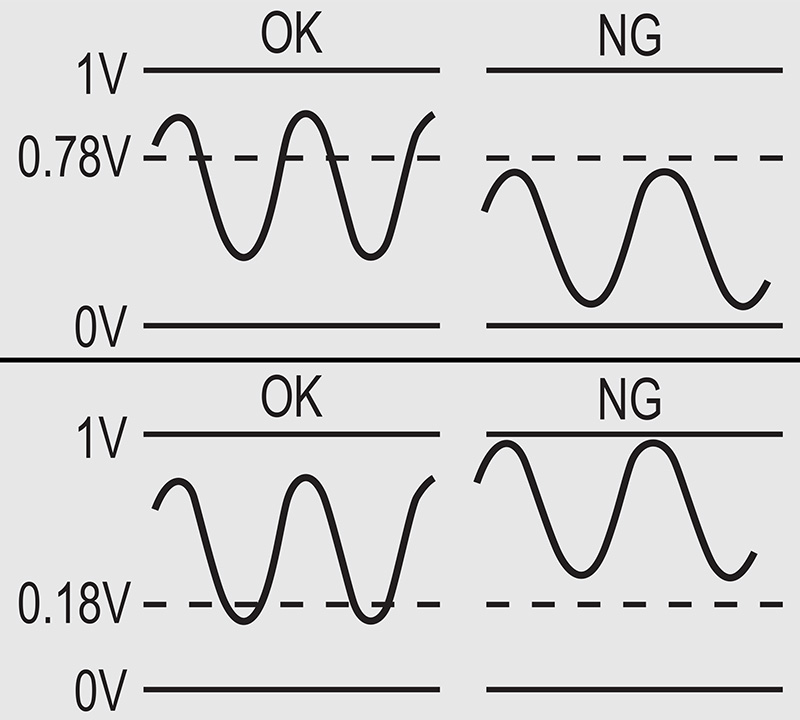
The rear heated oxygen sensor is used to check the effectiveness of the catalytic converter. If performing as intended, the sensor should output voltages that swing from below 0.18 V to above 0.78 V.
If the rear oxygen sensor does not swing above 0.78 V and below 0.18 V as it switches from rich to lean and back, you can use CONSULT III PLUS to command injector pulse width up 25 percent and down 25 percent. If the voltage output signal still does not hit its minimum and maximum targets, you can suspect a faulty sensor.
Is the O2 sensor signal getting to the ECM?
Before condemning an O2 sensor, you need to determine whether or not there are any opens or shorts preventing the sensor’s voltage signal from reaching the ECM. You’ll need to simulate rich and lean conditions at the O2 sensor and watch to see if injector pulse width (short term fuel trim) and carbon monoxide (CO) level in the exhaust changes in the appropriate direction.
In newer O2 sensors you should be able to simulate rich and lean conditions through commands in your Nissan CONSULT III or with a high level aftermarket scan tool. With older O2 sensors you can add propane to the air/fuel mixture to force a working O2 sensor to see a rich condition. If the system shortens the injector pulse width in response to the propane, that tells you to check for plugged injectors or other causes of a system not adjusting STFT lean when needed.
Reference air pathway restricted
Outside (non-exhaust) air enters the reference air chamber through vent holes in the housing of old style oxygen sensors. Newer oxygen sensor designs bring outside air in through a channel actually built into the wire. If these ports or channels are blocked or restricted, the oxygen sensor will not be able to “breathe” in outside air. The two chambers in the sensor will not accurately reflect the difference between atmospheric and exhaust levels of oxygen. The rich versus lean condition in the exhaust will be reported incorrectly to the ECM, leading to skewed fuel trim adjustments.
Inspect the sensor to make sure that dirt, airborne contaminants, and leaking oil and other under-hood fluids have not entered the ports in old style sensors and blocked the air pathway. On newer sensors, check that reference air channel openings in the wire connectors are not plugged with contaminants or crushed. Also, make sure that no sealant, dielectric grease, or other materials get into the connector, where they could restrict air flow into the air channel in the wire.
Higher A/F sensor ground voltages
When testing the ground side of the A/F sensor, you need to connect to the sensor’s ground, not chassis ground. This is because the A/F sensor circuitry is very sensitive. It does not do well handling interference that could come through the chassis. So manufacturers design the A/F ratio sensor to be grounded through the sensor, or use a floating ground from another sensor on the vehicle. Expect to see a higher voltage for the A/F sensor ground than the 0 voltage value of the typical chassis ground.
Cracked ceramic
The zirconia in an O2 sensor can last tens of thousands of miles. That is, unless you drop it or bang it around in the shop. If you drop or hit an oxygen sensor with a wrench, you may crack the ceramic element, which is what separates the reference air chamber from the exhaust gas. Once the ceramic is cracked, exhaust gas can flood into the reference air chamber. That will throw the reference comparison off balance and result in a biased voltage reading. You are unlikely to see the crack, as the ceramic is embedded in the sensor. If you dropped it or hit it hard, replace the sensor.
Mode $06
You can use Mode $06 test data to identify O2 sensors and other components that haven’t yet set trouble codes, but are close to the minimum or maximum limit of their factory-specified operating range. This is useful because an O2 sensor that is close to failing but has not set a code may still cause damage to the catalytic converter.
Mode $06 also includes a subset of additional O2 sensor data points, including a signal amplitude test, a switch point test, and a heater circuit amperage test. Each test has upper and lower limits that are set to ensure ideal emissions performance for the specific year and Nissan model. The additional tests may help you see that, even though the O2 sensor has not set a code, it is losing effectiveness in one or more key functional areas and should be replaced.
There are 62 different oxygen sensor codes in the on-board diagnostic (OBD) system, not including manufacturer-specific codes. Nissan does a really good job of providing clear, detailed, step-by-step diagnostic and repair procedures for many oxygen sensor-related trouble codes. Refer to the Engine Controls (EC) section of the service manual for trouble code diagnosis procedures. Study the differences in oxygen sensor type, their control strategies, and any applicable technical service bulletins, and you’ll be delivering perfect combustion to your customers.


0 Comments