
Tools Used |
| 90 amp clean and stable power supply |
| Ross-Tech VCDS with screen capturing software |
| Vacuum gauge, camera and note paper |
| Banding/crimping tool |
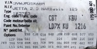
| VIN: 3VWJM31K68Mxxxxxx |
| Mileage: 359,650 km – 223,476 mi |
| Part No SW: 07K 906 032 BJ |
| Component: 2,5l R5/4V |
3 Faults Found |
| 008825 – Leak in Air Intake System P2279 – 008 – Intermittent – MIL ON |
| 000369 – Fuel Trim; Bank 1 P0171 – 004 – System Too Lean – MIL ON |
| 001287 – Idle Control System RPM P0507 – 001 – Higher than Expected. – Intermittent |
History
This particular Jetta owner asked that we look at this model because of a starting and idling anomaly that was repeated in the facility and had concerns in relation to idle quality.
Those concerns were immediately repeated and what was discovered was due to very poor service procedures and damage to the air box.
The damage also included the air filter and cover.
Hint
Extra and detailed testing with the detached cover on this engine can be easily accomplished if the MAF is removed from the cover and attached to the air inlet. If these models are tested and are in service in the shop, keep a known good spare MAF for test purposes and that will save precious time.
As in every article, these examples help identify the exact model with the:
- Matching VIN and model
- Sales code: 1K2 7S3
- Engine code: CBT
- Transmission code: KBU
- With erWin, the exact service procedures, specifications and schematics can be accessed with locations.
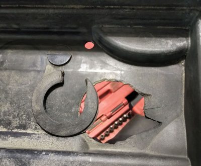
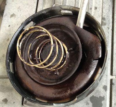
This view of the air filter leads to the assumption that the previous service facility was a little “rough” with the cover that was housing the air filter.
An attempt was made to use a two part metal epoxy to repair the cover and minimize the damage to the air filter. The attempt included affixing the rubber grommet to the stays/pins on the valve cover.
Frankly, I was rather proud of myself that it fit and held the position of the main engine cover. The die grinder and multiple layers of epoxy over time created a work of art.
Side Note 1
All the while when this air filter box was worked on, there was much “rodent left over” of material, seeds, twigs, etc. etc. including material on the engine valve cover and coils — so much, it was saved for the vehicle owner.
The repair to the engine cover will not address the lean or improper idle condition. The lean/idle condition is attributed to a vacuum loss and has to be identified as either internal (engine mechanical components) or external (engine vacuum connections).
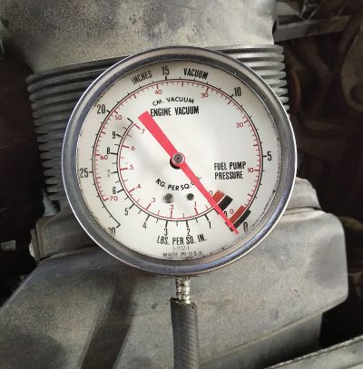
A sure way to test a theory on this engine is to disconnect the vacuum source at the PCV system and cap it. Measure (using a vacuum gauge) at the dipstick with or without the PCV hose attached.
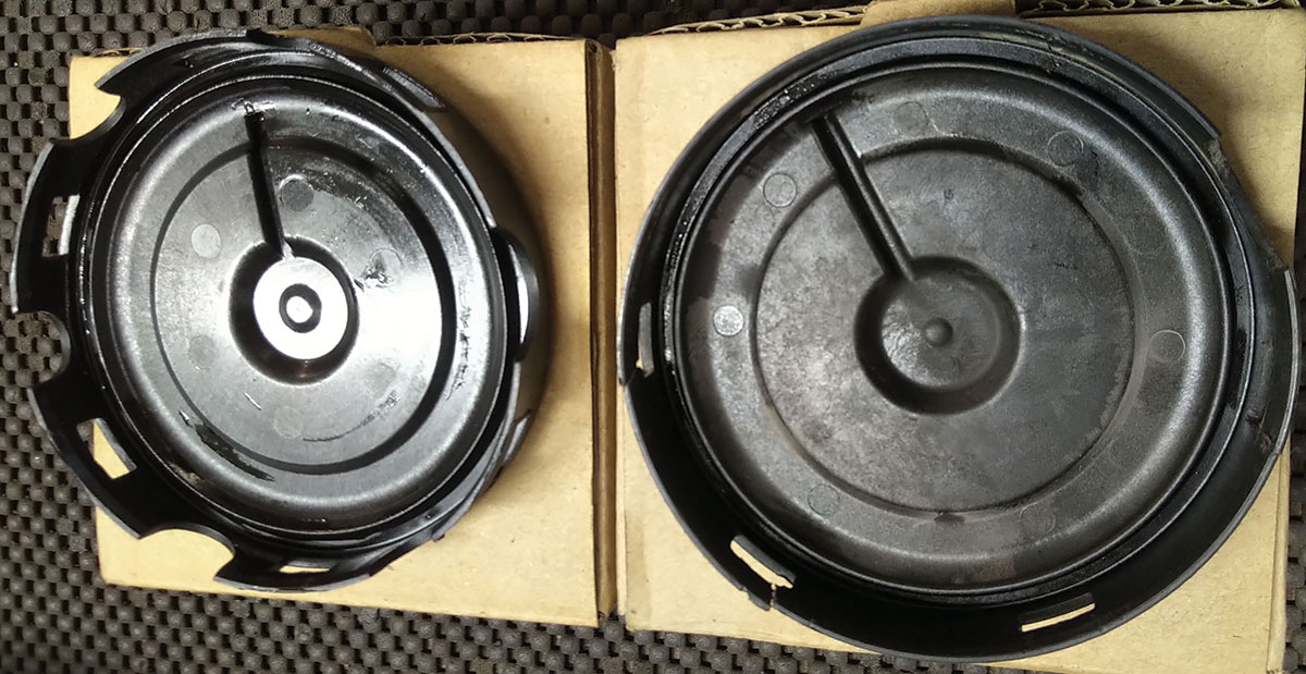
As with anything, sometimes a replacement part is found that will solve the “torn diaphragm” syndrome. With some cleaning and re-assembly with a replacement, the fuel trims and faults were deleted and idle quality returned to normal. Note the replacement is an aftermarket part.
Be advised, when faults are deleted with VCDS, ALWAYS reset the throttle adaptations in basic settings group 060 and 063. Then proceed with live tests and logging. Measure the trims and see that the trims are now reasonable.
End of story right?
What was replaced?
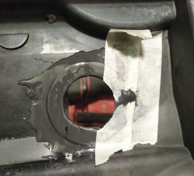
The Jetta returned two weeks later with a similar problem but the plastic PCV cover failed due to heat distortion and, this time, we heard the external vacuum leak. The “work of art” failed because of heat as well and that’s where Lewis Black’s rants reminded us all of human frailty.
Time to inspect
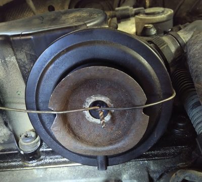
The redneck solution was to tie a large washer to “push” on the cover and keep the distortion minimized. It worked as a temporary solution until another replacement version arrived.
While this test was a success, the measurement was done again at the dipstick tube with the following result: Very little vacuum was introduced into the engine.
The next solution was mentioned during a conversation about the replacement cover “clip openings.” The discussion was about how the manufacturing process lacked the correct dimensions. There was a difference (height) in the clip openings and the way the cap appeared weak. The difference being, how the cover’s openings grabbed the tangs of the valve cover/PCV port.
Side Note 2
The rodents returned again and left another mess on top of the engine valve cover and ignition coil area.
The solution
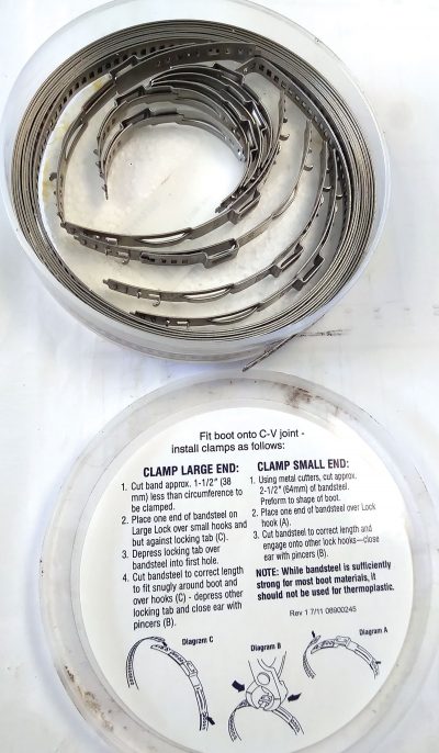
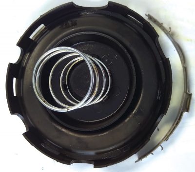
We found a kit that is used to “band” C-V boots to the axle shaft. This kit offered a perfect solution to keep the replacement cap in place.
- Calculate the length needed.
- Use the correct clip to attach the length of band.
- Push or have the cap tied firmly in place.
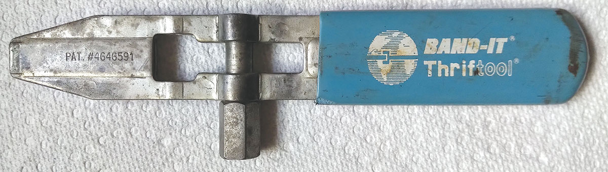
- Use the correct tool to squeeze” the clamp onto the cap.
Why?
Cost effectiveness and at 359,650 km or 223,476 miles we could not justify the cost of a replacement valve cover if we can “patch it” with a little thought and finesse.
Another solution is with this tool that was purchased some time ago. Needed is one clamp that was difficult to find but not impossible.
Appreciation
The customer returned a few days later with a big bag of cashews, tangerines, and a thank you to all with a great big smile.
Side Note 3
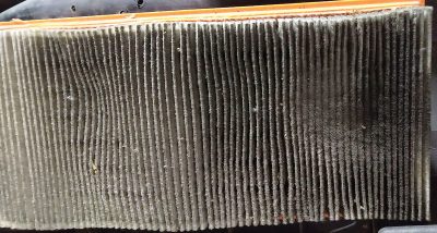
The rodents returned again and this time they had a party at the dust and pollen filter. The customer complaint this time was the smell!
After the third attempt with the pesky rodents and a new filter, the battle raged and continued at the pharmacy.
How to get rid of pesky rodents 101
- Find some pill bottles and drill multiple holes into the side.
- Find some moth balls and fill the bottles.
- Cap the bottles with the mothballs.
- Place the pill bottles with the mothballs in strategic locations around the engine bay and inlet to the dust and pollen filter.
- Replenish the mothballs from time to time.
Explanation and operation “If – Then – Else”
If for any reason a vacuum gauge at the dipstick tube displays relative engine vacuum, then the PCV valve likely has a damaged diaphragm or the valve cover is mechanically damaged/cracked.
If the vacuum gauge reading is reading much lower than engine vacuum, there is a good chance the valve cover and diaphragm are intact.
Download PDF


0 Comments