
This topic is covered in a short series. Parts 3 and 4 will discuss energy management and PCV Ventilation System Testing.
Part 3: Energy Management
With VCDS and a little work, the energy management system (Address 61 Battery Regulation) was looked at much more closely to see if anything was missed and required any adjustments/replacement.
One issue is coding and how to “register” a new battery. Realize that the dealer batteries have a serial number. That number may include a date code. If the date code is too old, the energy management system may likely react to the date code. Take that statement with a few grains of salt.
Go back to Part 1 and look at the first line “Extra” and notice the display. The same data is within the scan. Part 2 indicates this data:
Subsystem 1 – Part No: 4F0 915 105 C
Component: von VA0 1504240113
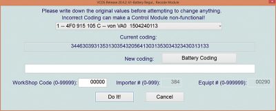
With VCDS and IF a serial number or current coding is known, the replacement battery may be registered. Don’t attempt to write or change the coding in any way unless it is perfectly correct or use the original code.
This is the example of this model via drop down list.
In many cases if the battery is equal to or better than the original, we’ve used the original “Current coding,” copied and pasted that long string into the “New coding” section and clicked “Do It!”.
Energy Management Live testing via VCDS and the MMI display
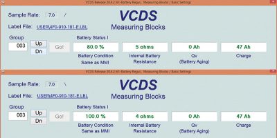
With these two images stitched together, the battery condition in group 003, field 1 mirrors the Multi Media Interface (MMI) display that the technician and or vehicle owner has access to.
The condition of 80.0 percent was the result of NO power supply attached and reading/testing the groups of Address 61 for approximately 15 minutes.
This model needed some “tweaking” of the original label to identify a few unknown groups with some added descriptions. The engine was later started and ran for 30 minutes.
The significance of this test is how the system reacted after the engine was started and how the alternator reacted to the vehicle load as it was applied.
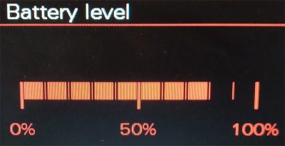
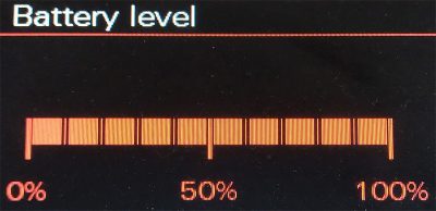
The following two MMI images coincide with Address 61 group 003. With VCDS and the MMI in view to monitor battery percentage level, both images will match. That data between VCDS and the MMI is all shared via CAN messaging between the Energy Management system and the MMI.
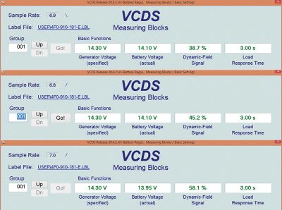
With the engine running and adding a parasite/load to the system, VCDS can also monitor the rate or percentage of charge when the alternator is requested to “ramp up.” The load introduced included the engagement of the vehicle lights, A/C system and the rear defogger. This next image is stitched together to offer an increase of the alternator field strength (Dynamic-Field Signal).
With VCDS, Address 61, Group 001 field 3, the alternator ”Dynamic-Field Signal” can an be seem as increasing with added load.
Another simplistic test can be with a “Carbon Pile” attached to the service battery. With VCDS at the rear of the A6 and gently controlling the carbon pile, the ”Dynamic-Field Signal” can be controlled at will.
This simplistic test will be an aid to measure the ”Dynamic-Field Signal” and will match a connected AMP clamp directly at the battery negative cable.
Consider this as a valid test. Dig out your meters, carbon pile, AMP clamps with VCDS and prove this yourself.
On a next set of articles, there will be some deep thought and analysis with parasitic draws, known good/accurate test setups, and definitely putting to rest many unreliable misconceptions.
Something to think about
If it has been professed that a network may go to sleep between one and two hours, would one suspect multiple dead batteries all over North America?
In all of the tests over years of finding parasites, anything more than 30 minutes doesn’t indicate “sleep mode,” the indication is a defect.
Therefore a one amp draw will definitely deplete a battery on a regular basis. The “magic” and industry number followed should be close to 30 mA. The A6 that was tested had recorded 20 mA in sleep mode.
Visit these helpful links for more information:
dwyer-inst.com/Products/ManometerIntroduction.cfm
sperryinstruments.com/en/smartmeter
Part 4: Ventilation System Test
Many models like VW and Audi have an oil separation or PCV ventilation system that can misbehave at times. Most of the time now, these models are tested and recorded for our future use. There have been occasions when we see lean condition errors that other shops tend to misdiagnose, with several parts installed that lead nowhere for the vehicle owner.
As with anything that enters the “Lab,” we scan, save, and delete the errors.
At times a combined city and highway road test may trigger the faults but this test is quick, simplistic and inexpensive. Take the time to ask the vehicle owner about past records and invoices.
Attempt to discover what replacement parts have been installed and their quality. This is all about trust with the vehicle owner.
The indicators of faults can be simple things like an oil leak, cracked hoses or plumbing. Try these tests and maintain records to measure the differences over time with different models and configurations.
When simple testing doesn’t offer values as “normal”, then consider the “never lies” smoke machine to find those illusive leaks.
The first step is to measure vacuum at the dipstick opening (if there is one).
When data has been captured and saved, re-insert the dipstick for the next test.
NOTE: Finding and making up any test equipment should be snug to the connection and safe to ensure no personal or vehicle damage.
Always assume any gasses in the service bay are dangerous to you, staff and customers in the building. Maintain ventilation at all times.
If past articles have been read, there is a cheap, easy tool that has been repeatedly used on VW, Audi and even those pesky BMW models.
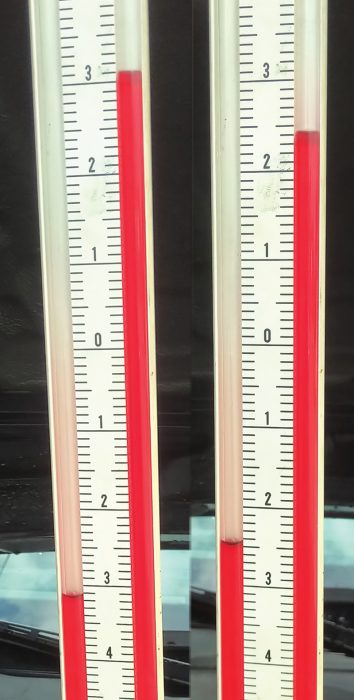
This simplified test indicates a healthy ventilation system, near “0”.
Keeping things simple and having ready access to this type of tool may offer un-noticed conditions that may require a repair, especially lean or rough running startups. High readings for this system indicates an internal leak.
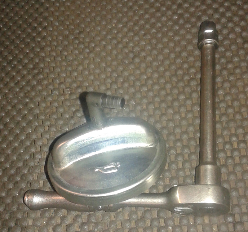
The oil filler cap was a purchase at the local import parts supply house and the only change was to drill a tight fitting hole to accept a new battery vent elbow. Any positive or negative pressure at that glued port must be open to the engine for measurements.
The glue used is the two part JB Weld. With the slack tube manometer attached, one side is open to the atmosphere; the other is attached to the oil filler test cap.
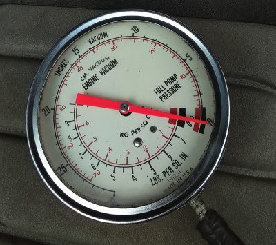
With the vacuum gauge attached to the dipstick tube, very little vacuum should be recorded. This test can also be used, with care, to measure unusual crankcase pressures. With the images provided, this can be used as a guide of a known good test for this 3.2L direct injection model.
This particular test will offer the condition of the oil separator system. Large amounts a vacuum may explain these lean running conditions on startup or constant circumstances while running. This simple test also indicates the possibility of future engine management repairs.
Measure these systems and maintain records to share between years, makes and models.


0 Comments