

With the advent of On-Board Refueling Vapor Recovery (ORVR) systems, and even tighter restrictions on emissions standards, the Evaporative Emissions System will continue to challenge repair technicians.
Since hydrocarbons were first identified as Volatile Organic Compounds (VOCs) and determined to be a major contributor to photochemical smog by the EPA, the need for a sealed automotive fuel system has been evident. The first evap systems were little more than a can full of charcoal pellets to trap fuel vapors and a few rubber hoses to purge the canister. They relied on venturi vacuum to draw the vapors into the base of the carburetor to be burned off with the air/fuel mixture, harmlessly and unnoticed.
The systems remained basically the same until the institution of OBD II, computer controls, and self-monitoring. Modern evaporative systems have evolved significantly and are now a complex collection of piping, valves, and solenoids. With the advent of On-Board Refueling Vapor Recovery (ORVR) systems, and even tighter restrictions on emissions standards, the Evaporative Emissions System will continue to challenge repair technicians.
Tools of Testing – Smoke Machine
The smoke machine is typically the first tool that comes to mind for evap testing, and for good reason. It is a very useful tool and is very effective in locating system leaks. There are a variety of machines on the market, and they are not all created equal.
Some smoke machines offer the option of only applying air pressure without the smoke. This is the best method to start testing with. Test the system first with air only and monitor the flow gauge. If there is no leak present, then there is no reason to turn on the smoke. This saves the smoke producing fluid, but, more importantly, it saves the charcoal canister. Repeated smoke testing can contaminate the charcoal pellets in the canister. Several vehicle manufacturers warn against using the smoke machine for more than two consecutive 5 minutes cycles.
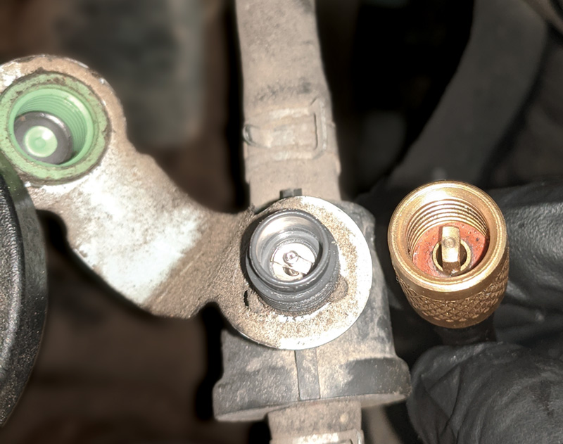
Make sure to remove the Schrader valve from the test port if the adapter does not have a tab to depress the valve. The Schrader valve has left hand threads and needs to be turned clockwise to be loosened. The valve core requires very low torque, and the plastic test port housing can easily be damaged if the valve is over tightened.
It is possible for a leak to be difficult to find using smoke, due to the leak being so small that the smoke particles are not visible to the naked eye. And in some cases the smoke can be absorbed by the gasoline in the fuel tank and will not be seen. An alternative option to the traditional smoke test is to use a tester like the BULLSEYE leak detector from Automotive Test Solutions. This tester fills the evap system with regulated CO₂ gas from a separate cylinder. The evap system is then ‘sniffed’ with the sensitive leak detector wand, or a leak detecting foam can be used that changes color when it encounters the CO₂ gas escaping from the leaking area.
One other thing to remember when testing with a smoke machine is that smoke machines apply a small positive pressure into the system along with the smoke. Most evaporative systems use vacuum or negative pressure to perform self-tests. However it is possible that the positive pressure that the smoke machine applies could seal a leak in certain circumstances.
Gas Analyzer
A four or five gas analyzer is also an excellent tool for testing evap systems. Gas analyzers are not a tool that all shops will have, but if one is available as part of smog station equipment or as a shop tool, don’t overlook it as an option when searching for evap leaks. The wand of the gas analyzer will easily pick up any hydrocarbons leaking out of seals or hoses, specifically if a leak is suspected on the top of the fuel tank and cannot be easily seen. A spike in the hydrocarbons reading when the wand is moved past a fuel tank seal, rollover valve, or charcoal canister will confirm a leak.
Lab Scope
An oscilloscope may seem like overkill for a simple purge or vent valve circuit, but it offers a great picture of the operation of the valves. A lab scope works as a video volt meter, allowing voltage and current values to be seen in real time. By using two channels, one for each wire of a vent or purge valve, issues with the supply voltage, ground control, or voltage drops will be immediately visible. Adding in an amp clamp will show the ‘work’ being done by the component.
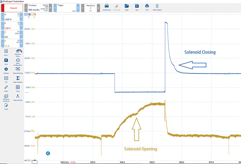
An additional benefit of using an amp clamp is to see the mechanical movement of the valve. A motive ElectroMotive Force, or EMF, is induced when the metal core of the valve moves from an open to closed or closed to open position. The movement of the valve can be seen in the current and voltage waveforms as a small hump. This hump indicates that there was mechanical movement of the solenoid valve being tested. The solenoid opening movement will be reflected in the current, and the closing movement is shown in the voltage trace.
Remember that just because a valve makes a clicking noise does not mean it opened or closed, however. A valve can make a clicking sound but be mechanically stuck or clogged. Don’t rely on sound alone to confirm the operation of a canister closed valve or purge valve.
The lab scope also provides the ability to monitor the entire evap system while performing an In-Bay Self-Test or running the evap monitor. With three channels of a lab scope connected to the purge valve control wire, vent valve control wire, and the evap system pressure sensor signal wire, the entire operation can be monitored in real time.
Diagnosing Evap Faults – Check the Basics First
Approach an evap system fault in the same way as any other type of fault on a vehicle, by checking the basics first. In the same way that fuses should be checked at the start of an electrical diagnosis, check the basics of the evap system first. An overall visual inspection of the system is a great place to begin.
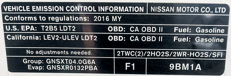
Check for the correct vacuum hose routing to the purge valve, and plastic piping to the vent valve and canister. Inspect for aftermarket parts and previous repairs. Check the under-hood Vehicle Emission Control Information label to determine what evaporative emission components are on the vehicle and what type of emission standard the vehicle has.
There are many different emission standards including Low Emission Vehicle (LEV), Ultra-Low Emission Vehicle (ULEV), Super Ultra-Low Emission Vehicle (SULEV), and Partial Zero Emission Vehicle (PZEV). Knowing which standard is present on a vehicle can aid in the diagnosis and may be needed when order parts. Keep in mind that PZEV vehicles have a completely sealed, zero emission fuel system, and are required to have a 15 year, 150 K mile warranty on emission control components.
The following brief vehicle study illustrates the importance of performing basic checks first.
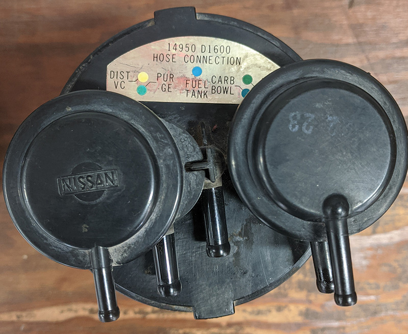
A Nissan Altima was brought into the repair facility with a P1441 very small leak fault. The fault had been present for some time and the car had been at several repair shops. Every component in the evap system had been replaced except for the fuel tank, with several components being replaced multiple times. Smoke testing the system showed a sealed system with no leaks, but the very small leak fault would return every time it was cleared.
After performing a basic visual inspection of the system, the problem was quickly determined. The actual problem with the vehicle was that the two vacuum hoses at the purge valve had been installed backwards at some point during a previous unrelated repair. After the hoses were returned to their correct positions the Evap. Readiness Monitor ran and passed. This was an easy repair, but it had been overlooked by several technicians. Always check for the correct hose routing and that the correct OE parts are installed on the vehicle. Many aftermarket parts have functionality issues, or a significantly shorter lifespan.
Review Technical Service Bulletins
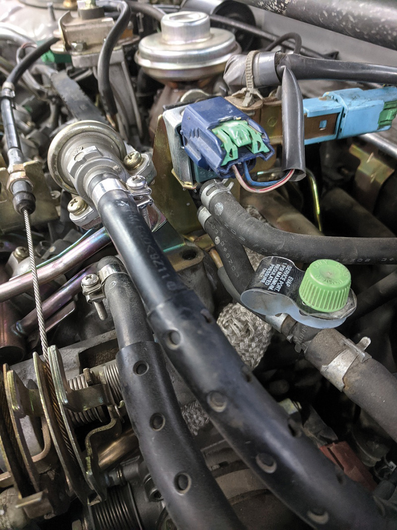
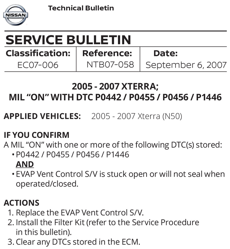
Always review technical service bulletins before testing begins. Bulletins may reference updated components or test procedures that can save valuable time and ensure a correct and complete diagnosis. Take Technical Bulletin NTB07-058 for example, which covers the 2005 – 2007 Xterra. The Nissan Xterra remains a popular compact SUV, even though production ended in 2015. The rugged design paired with 4-wheel drive make it ideal for off road travel.
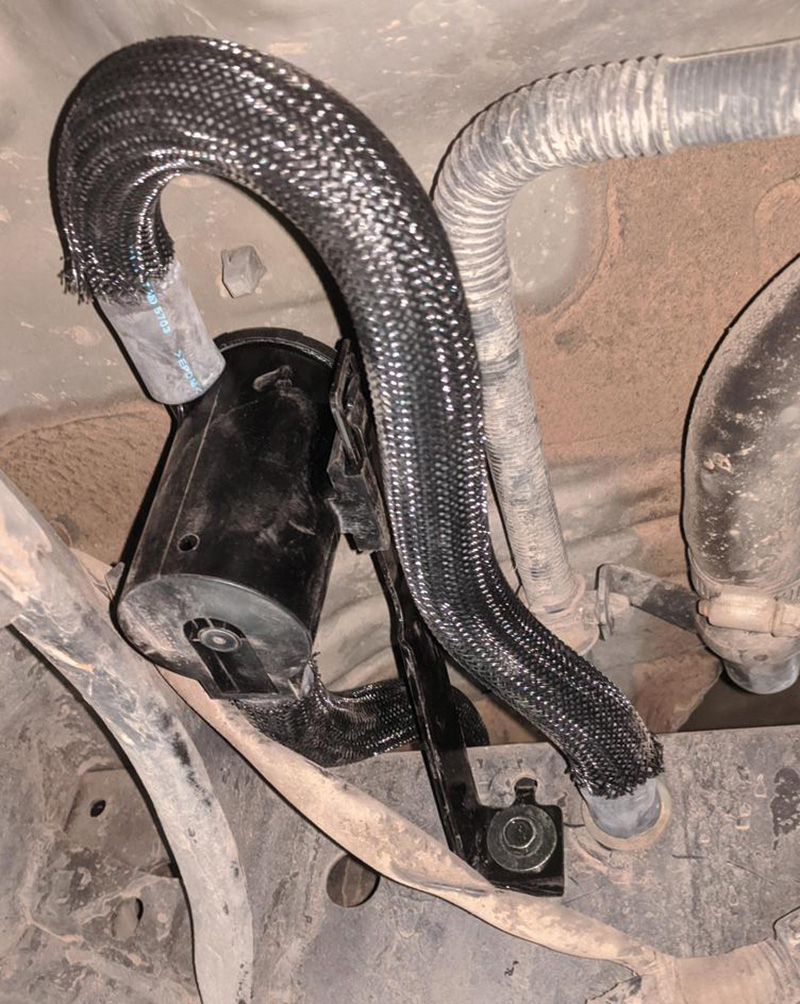
Dirt roads are a major contributor to the conditions described in the bulletin, however. The vent control valve, vent hose, and charcoal canister can become clogged with dust and dirt, causing the Check Engine light to illuminate and one or more faults to be stored. The bulletin lists an updated vent control valve as well as a filter kit, which relocates the vent hoses and includes a new filter which will help prevent the clogging from happening again.
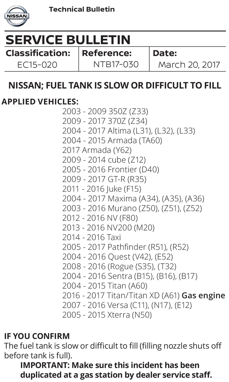
Other notable bulletins include NTB17-030, which outlines testing and repair procedures when a fuel tank is slow or difficult to refuel at the gas pump. Typically, the owner of the vehicle would state that the filling nozzle shuts off before the tank is full, or that it takes an unusually long time to fill the fuel tank. This bulletin covers a variety of vehicles from model year 2003 to 2017. In some cases, a restricted vent hose can be replaced, while other vehicles require the entire fuel tank to be replaced due to internal valving.
A second notable bulletin is NTB17-082D, which also covers almost all Nissan vehicles from model year 2008 to present. This bulletin addresses fault code P0456 when caused by a leak at the vent control valve o-ring.
Confirm the Repair
After a fault or leak has been diagnosed and repaired, it is strongly recommended to use the Consult III to perform any available evap self-tests under the Active Test tab, or road test the vehicle to run the Evap. Readiness Monitor. This is an extra step that adds time to the overall repair, but it will prevent the vehicle from returning with the Check Engine light on again. For example, if a large system leak is identified and repaired, it is still possible a small leak could be present that went undetected by the evap monitor due to the large leak.
The Evap. Readiness Monitor is considered a non-continuous monitor because certain vehicle and driving conditions need to be met before the self-tests will run. This is not entirely accurate, however. There are electrical faults for the purge volume control valve, vent control valve, and evap system pressure sensor that can set after two key cycles. A 2016 Altima has ten main evap system fault codes, six of which are component or circuit electrical faults.
Knowing the conditions for running the evap monitor can be very useful for confirming a repair, passing an emissions test, or clearing a Permanent Diagnostic Trouble Code (PDTC) on model year 2011 vehicles and newer.
The best place to find the conditions for running the evap monitor, or any other monitor, is in the factory service information. If service information is not available, or monitor enabling conditions are unclear, an alternative option is to view the freeze frame data for the fault code. The freeze frame will list the intake air and engine coolant temperatures, throttle position, rpm, and mph. Driving the vehicle under the same conditions will give the best chance of running the monitor.
Final Vehicle Case Study
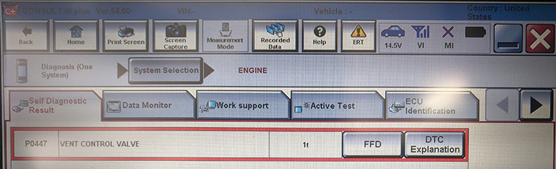
A 2015 Nissan Sentra equipped with a 1.8L MRA8DE engine was brought into the shop with a Check Engine light illuminated. The initial scan found two fault codes: a P0101 Mass Air Flow Sensor, and a P0447 Vent Control Valve.
After verifying that the MAF code was related to service bulletin NTB16-027d, 2013–2018 Sentra: MIL on with DTC P0101 and would require an ECU update, focus was shifted to the evap fault. The evap fault was current (indicated by the red text color on the Consult fault screen) and would not clear out of memory.
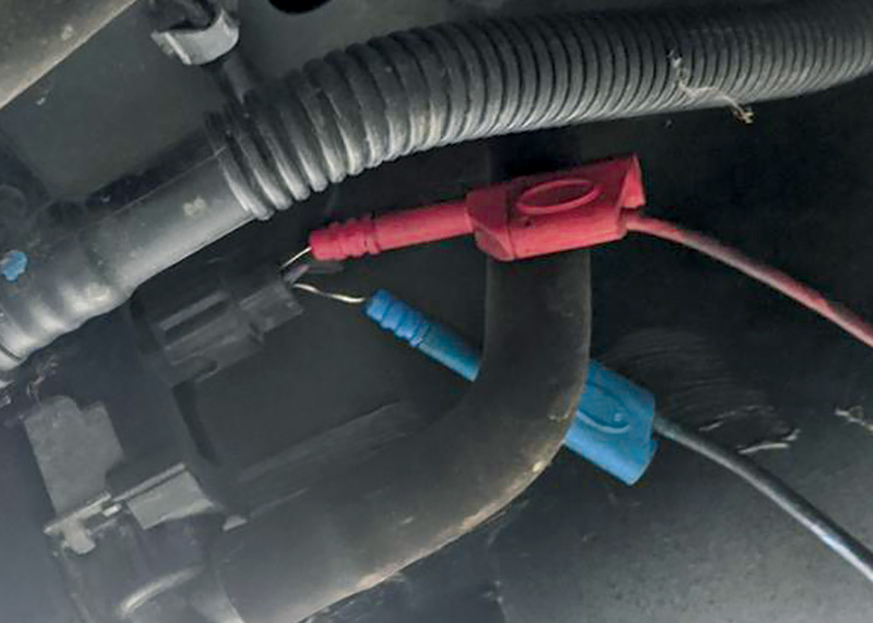
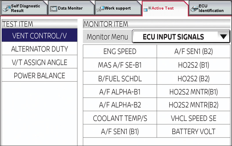
A brief review of the code description and code set data showed that this was an open circuit fault, and it would set when “An improper voltage signal was sent to the ECM through the evap canister vent control valve.” With this data in mind, a lab scope was connected to both wires at the vent control valve, and then the valve was electrically controlled with the Consult III scan tool. This function is found under the Active Test tab, and it allows multiple data PIDs to be viewed while commanding the valve closed or open.
The test showed battery voltage on both solenoid wires, whether the valve was being commanded closed or not. This verified the supply voltage to the vent valve was good, and that the vent valve was not the cause of an open circuit, since voltage could pass through the solenoid windings. The ground control signal was not making it to the vent valve though, indicating a wiring issue or possibly a faulty ECM.
The next step was to access the engine controller under the hood and see if there was a ground control signal present at the connector. The vent valve was commanded shut again with the scan tool, and there was a ground control signal present at the ECM connector. Somewhere between the ECM and the vent control valve was an open circuit. Finding an open circuit in a situation like this can be like a rundown in baseball, where a runner is stuck between two bases trying to not get tagged out. Test each side of the circuit and gradually work toward the middle until the open circuit is found.
The harness for the vent valve passed through the underbody of the vehicle and into the right rear fender. There were no problems found in the harness section under the vehicle. After removing all the contents of the trunk (including a vintage Buffy the Vampire Slayer board game) and inspecting the rest of the harness, the problem was visible. There was a small rodent nest right where the wires passed through the body, and the wires had been chewed apart.
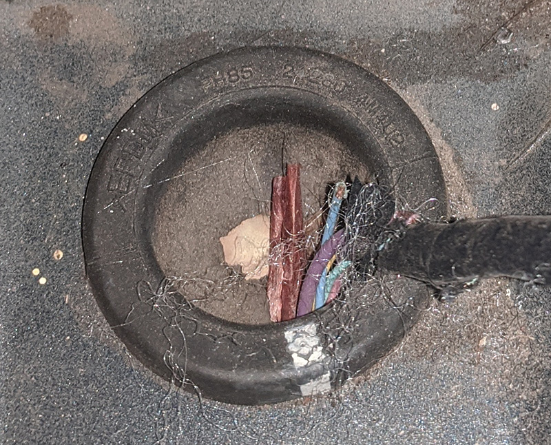
The wires were repaired, and the rodent nest removed. The vent control valve fault was cleared and did not return. After reprogramming the ECM for the Mass Air Flow fault, this Sentra was sent on its way home.
Checking the basics, following a logical testing procedure and reviewing service bulletins will result in the correct repairs being performed the first time, every time. We all can use a reminder to review our testing procedures and identify areas that can be improved upon.


2000 Maxima. Any tech bulletins for PCV and evap systems?
Hi Theodore,
The author found some info that we hope will help: