
The first in a series of articles on Mercedes-Benz traction and stability control systems
Techniques to maximize the available traction, to go, to turn, to stop, have been around for a long time. Four-wheel-drive vehicles go back to the late 1930’s and probably earlier. Limited-slip and locking differentials, reducing the likelihood that the drivewheel with lower traction will spin loose, have long mechanical ancestry as well.
Some systems go back a very long way: Coal-fired Nineteenth-Century steam tractors sometimes used differential braking to grab back the traction when one of their iron-clawed wheels lost its grip in the dirt and started scrabbling down into the earth instead of dragging its plow along the furrow. The driver functioned at once as sensor, control unit and actuator; first dodging the flying rocks and clods, he heard the roaring steam and heaved to the corresponding brake lever with bicep power. Those three functions, electromechanical now and separate, remain the basis for current traction control systems, including our first:
Antilock Brakes
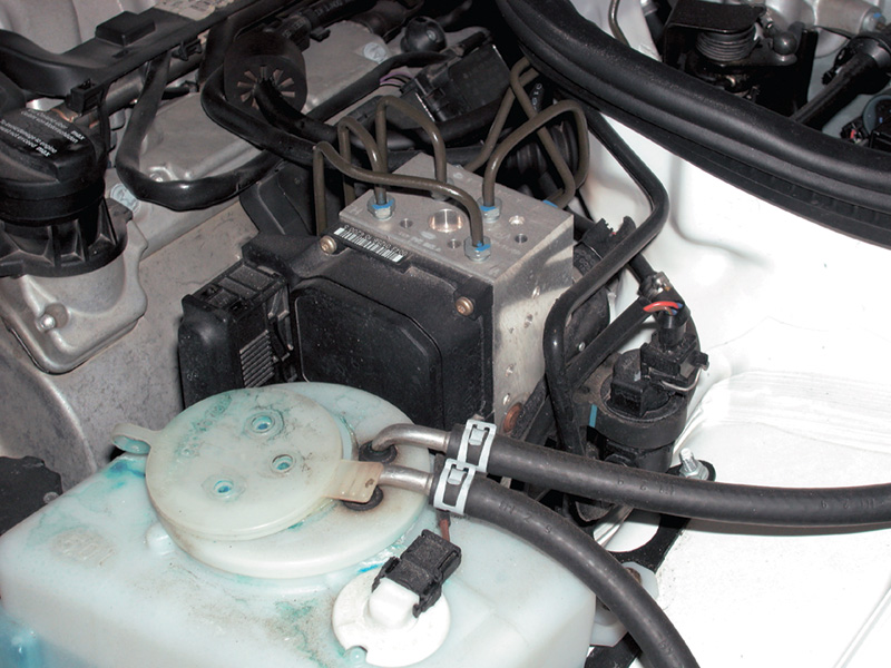
At the hydraulic heart of the ABS system is the hydraulic unit. This component sits on the brake fluid circuits between the tandem master cylinder and each wheel cylinder. When there is no need for antilock countermeasures, it is an elaborate coupling between the pipes in and the pipes out. When the control unit senses initial wheel lockup, the hydraulic control unit is the center of wheelspeed controls, of the selective reduction of brake force to specific wheel cylinders as needed to slow them without lockup.
Why would you want an antilock brake system, anyway? Why not just stop all the wheels as fast as possible in an emergency and skid to a halt? Because of the difference between static and dynamic friction. Static friction is the force holding two separate but stationary objects together, dependent on factors like the character of the materials and their surface quality, the force pushing them together and the temperature. A boulder resting on the ground stays put against the force of the winds because of static friction. Dynamic friction is the force between two objects moving with respect to one another. A boat moving through the water, an airplane through the air and a hockey puck across the ice are examples of dynamic friction. So is a car spinning out of control, with all its wheels locked by the brakes. In each case, the dynamic friction will eventually bring them together, but static friction between the contact surfaces can stop movement much faster and under control.
Static friction increases with pressure up to the point when it breaks free and the objects slide. Static friction is always greater than dynamic friction between the same objects. Set a brick in the middle of a plank and lift one end. Static friction will hold it in place up to a certain angle, but once it starts to slide it can probably scoot to the other end before you can drop your end, because the dynamic friction between the sliding brick and the plank is much lower than the static was. A parking brake holds a vehicle at a standstill on a hill by static friction, but (assuming neutral rather than park or a gear) once it starts to roll, increasing speed shows how much lower the dynamic friction is.
From the tire footprint tests we looked at earlier, you can see the problem of achieving optimal braking even under ideal circumstances. A traditional hydraulic-mechanical brake system can only deliver two different hydraulic pressures to the calipers, one pressure for the front, a lower but directly proportional one for the rear (front-wheel-drive cars use dual-diagonal plumbing, instead, but the point is the same).
If a driver were such an accomplished master of the pedal he could hold the front brakes with just the application pressure to achieve the ideal amount of slip, say five percent, the system has him locked into a specific pressure for the rears, a pressure determined by the proportioning valve, suspension height sensor or whatever mechanism is used. That may be just the right pressure for some set of conditions, but not for others if the pavement changed or temperature went up or down or if it rained or snowed. Toss in any side-to-side variation in pavement quality, and the best our accomplished master driver could do would be to optimize braking for whichever of the four wheels had the least traction! Add to the mix even the slightest turn, and you need four different application pressures, all to come from one foot on one pedal at one master cylinder. Ain’t gwine happen, Huckleberry!
 All the control you have over a moving car comes from those four grooved rubber parts not moving at all, those four sections of the tiretread in momentary contact, in static friction, with the pavement. While those contact patches constantly change, they are stationary with respect to the pavement as long as you have the car under control. As long as the brake pads don’t ‘lock’ to the turning rotors but the rolling tire treadpatch stays ‘locked’ to its pavement track, you’re still driving. Antilock brakes serve to prevent the first lockup and maintain the second.
The earliest of the traction systems is ABS, Antilock Brakes. Beginning on Mercedes-Benz cars in 1978 following research and development dating back over 20 years earlier for railroad and aircraft landing brakes, these systems have achieved a reduction in the number of accidents caused by loss of traction during braking and a reduction in the severity of such accidents as did occur. Thousands of people worldwide may be alive who would not be had their cars not included ABS. Your work keeping the systems functional is just as important. If a day comes when a customer walks into your shop and says, “Your ABS repair worked and just in time. All of us walked away from an accident that didn’t happen thanks to what you did,” you’ll remember that day and that customer as long as you own a wrench.
The engineering problems were actually simpler for trains and planes. Train wheels share their common axle, and locomotives corner… well, on rails or not at all. Airplanes usually make a single dead-straight stop from high speed and then stand on the tarmac until the brakes cool to ambient temperature long before the next sustained application. But cars do many other things on the road than trains or planes, so the much more complex objectives of antilock brakes have always been the following:
- Directional stability (rear wheel traction),
- Steering control (front wheel traction),
- Braking effectiveness (all wheels).
You can’t maximize each of these different objectives simultaneously. Perfect directional stability would mean you’d have to stop the car, lift one end with a floor jack and re-aim to the course you wanted to travel next. Perfect steering control might preclude brakes at the very time you want them most, and the shortest possible braking distance might leave the car wrapped sideways around a tree.
 Sorting out exactly what the system would do under what circumstances – prior to designing a mechanism to do it – took a long time and sustained imagination and effort. The engineers had to think of every possible ‘what-if..?’ and then translate the whole set into machined steel and microprocessor functions and hydraulics. Notice the first objectives have to do with direction and steering control; braking improvement comes only once those conditions are met.
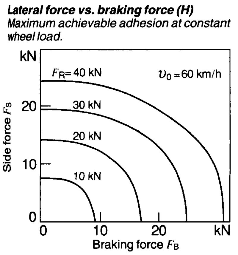
You often hear of the ‘circle-of-forces’ story for a tire’s traction. According to it, any given tire has a certain amount of traction, which we can quantify as the amount of force necessary to break it loose from the pavement and then visualize that force as the radius of a conceptual circle. You can, the circle-of-forces story goes, load that wheel with any combination of braking and turning forces so long as the combination of them does not add up to more than the radius of the circle of forces. This theory is a reasonably good, rough-and-ready explanation for a driver. Actually, however, a tire can conduct maximum acceleration and braking forces about 15 to 25 percent greater than the maximum cornering forces, because the treadpatch doesn’t squirm of twist as much stressed parallel to the vehicle’s centerline. The circle of forces is more of an ellipse, with the long axis in the direction of travel. The shape of the ‘ellipse of forces’ also depends on the tire’s aspect ratio and the sidewall stiffness.
Let’s consider a single braked wheel. For the moment, we’ll pay no attention to the rest of the vehicle or the other wheels and brakes, just our one specimen wheel and brake. How can a system prevent that wheel from locking up? For a given wheel and tire and a given pavement, there is a maximum static friction corresponding to the weight. It’s not a one-to-one relation, but it is close to linear. The best estimates are that an ideal rubber-tread tire against an ideal concrete pavement can yield a maximum of about 1.6-G’s deceleration force. No car can actually stop with that power and control, though some can come close. A car that could really achieve and hold that maximum grip on all its wheels simultaneously could, in theory, stop from a speed of 60 mph in about 1.7 seconds and just under 80 feet. That’s a juddering, hard deceleration: You might need a wire hook to fish your sunglasses out of the defroster duct.
But you can’t just extend the same system to all four brakes, because the interworking of the brakes can have adverse effects on directional and steering control. If under extreme braking force one wheel slipped even a little, its tirepatch would lose all the static friction, and the car would spin out of control. In principle, the brakes could stop a wheel much faster than that 1.6-G rate because of their enormous overcapacity to turn the vehicle’s kinetic energy into the random kinetic energy of heat, dissipated rapidly into the air.
 The limitation on the vehicle’s stopping capacity is not the gripping power of the brake pads against the rotors, but the friction between the tire tread and the pavement. If the vehicle were rigidly connected to the road, as if on a cogwheel railroad, it could stop much more quickly than 1.6 G’s, perhaps drilling your sunglasses through the windshield. But at least on cars, there are no such rigid connections from tire to road, so we want variable sliding (‘dynamic’) friction between the brake rotors and pads but static friction between the treadpatch and the pavement. Then we can vary braking with brake pedal force, as much as is compatible with the available tire-to-road friction.
 So you can encode in the antilock control unit information about the maximum speed at which the wheel can slow, translated into changes in wheelspeed sensor pulses per millisecond over a (very short) time. The control unit has an internal clock to detect the interval increase between the sensor pulses, as well as read-only (hardwired) data corresponding to the maximum possible deceleration. The control unit monitors the time of the interval between wheelspeed sensor pulses. It checks against its memory for the maximum allowable increase; if that internal change occurs or is exceeded, the wheel is locking up, so the control unit adopts countermeasures. If that interval change between wheelspeed sensor signals is exceeded, the wheel must have lost its traction against the pavement. Maximum braking force occurs when there is about a 5 percent slip relative to the pavement. Notice this does not mean that all of the treadpatch is slipping by 5 percent, but that 5 percent of the patch is slipping – quite a different thing.
Even then, there are sometimes reasons to reduce the available brake pressure below the maximum possible and to focus more on directional stability and steering control. If you’re driving on black ice with the right wheels and dry pavement under the left, you don’t want the left front brake to apply with so much decelerative force that the car pivots and spins left, sliding sideways into more black ice. We’ll see later how the early ABS systems were devised in such a way that the rear wheels sustained only such braking as was compatible with retaining traction on the wheel with less grip on the road.
ABS Functional Strategies
If the wheelspeed sensor signal indicates incipient wheel lockup, the control unit first triggers the hydraulic unit to close the valve to that caliper, retaining the existing pressure but not allowing the increasing pressure from the master cylinder to increase the pressure to that specific circuit. The other brake circuits can still accept higher pressure, but not the one threatening lockup. If that measure corrects the lockup, no further steps occur, and the system shortly thereafter allows pressure to increase with the others, sensor signals allowing.
If holding steady pressure doesn’t correct lockup, the control unit switches the valve in the control unit and reduces hydraulic pressure. Once wheelspeed resumes, the control unit then opens the valve and returns pressure from the accumulator to the master cylinder. The electric pump maintains pressure in the accumulator independently of any brake actuation.
 In early ABS-only systems, pressure to a caliper can never exceed pressure in the master cylinder. The entire process repeats rapidly to coordinate the driver’s braking intentions (as evidenced by pedal use) and the deceleration possible under the available traction circumstances. If problems are evident, there are separate relays (besides the overvoltage protection relay) for the hydraulic unit’s solenoids and for its pressure pump.
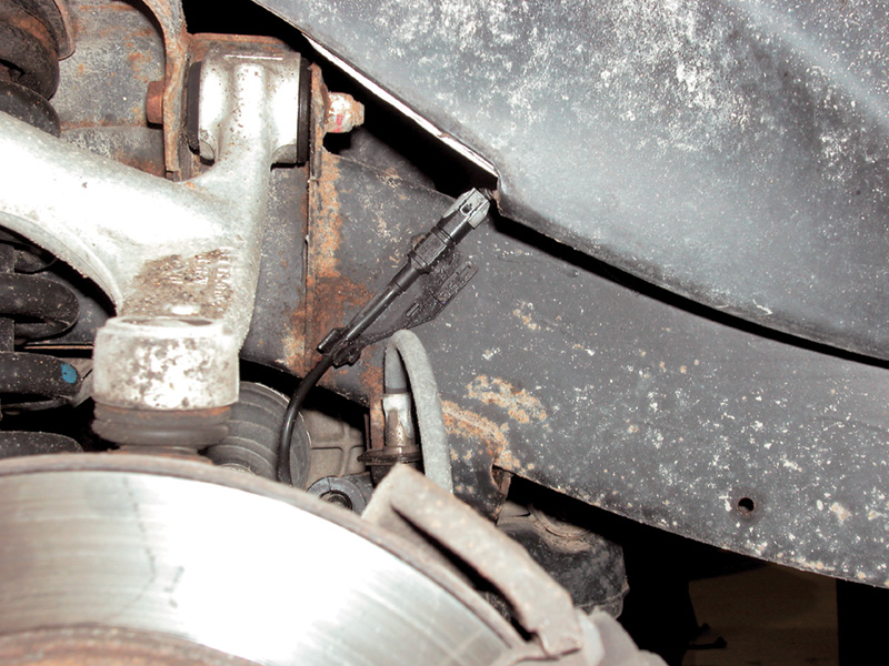
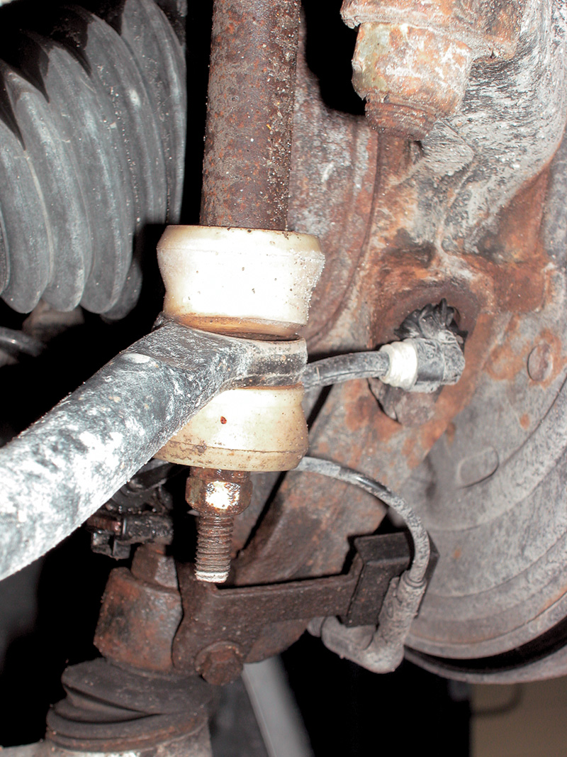
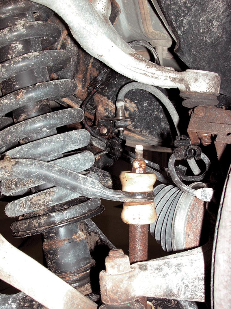
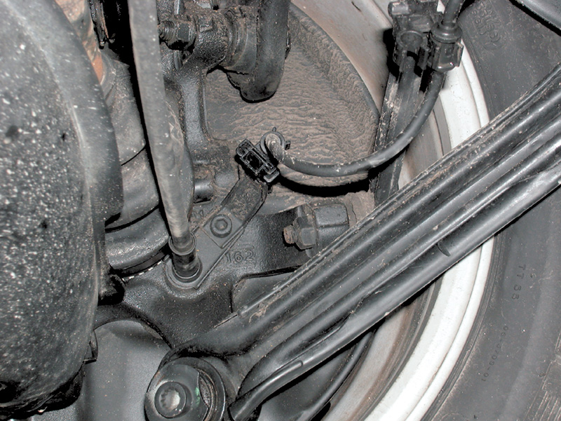
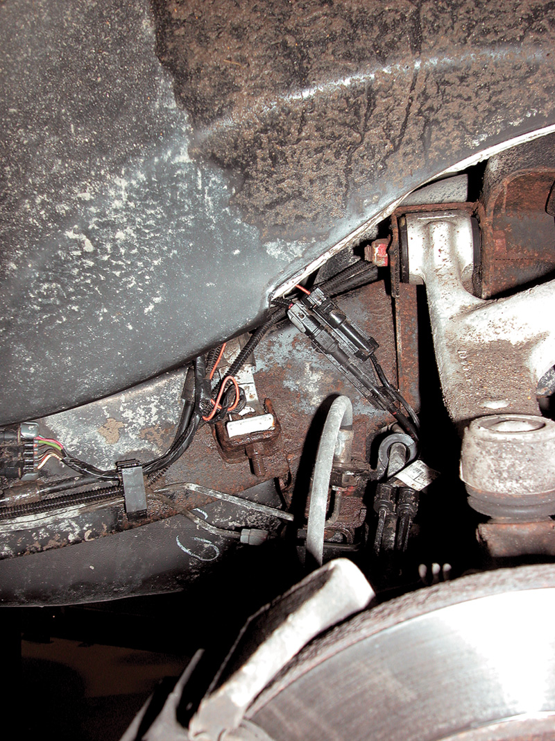
All ABS systems have separate wheelspeed sensors for each of the front wheels, mounted in the steering knuckles. You can follow the harnesses back along the suspension members and up toward the control unit.
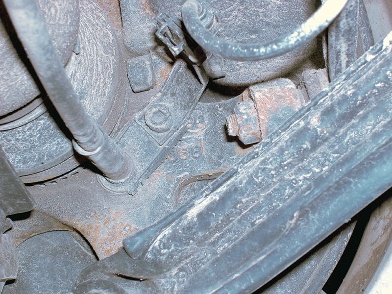
Early ABS-only systems used a single wheelspeed sensor in the differential case, directly measuring the pinion shaft speed rather than that of the wheels. The control unit’s programming correlated the signal ratios together. Since the rear brakes are pressure-modulated together, there was only need for the one speed sensor. This means, of course, that braking force is limited to the traction available at the wheel with less traction. Whichever one started to lock up, the system reduced hydraulic pressure to both until both turned at the same speed.
This initially seems odd, since that implies the system sacrifices some braking force. In fact, that’s exactly what it does. Recall that minimizing braking distance is the third of three objectives for ABS. Retention of directional stability is the first. You keep directional stability by retaining antisideslip traction at both rear wheels, whatever the other conditions. The system is working as planned when it cycles the rear brakes together.
Later systems (ASR, ASD and ESP) use separate rear wheelspeed sensors because they also control engine output and/or actuate differential locks or individual brakes to retain traction and directional control.
The complications in an automotive application arise from the complications of driving on real-world roads: variable quality of pavement, curves, bumps, variability of tire inflation. That’s not all. If someone has put different tires on one axle, perhaps snow tires, or a low-inflation spare anywhere, you can lose ABS altogether as the control unit toggles it off. Different tires, with different rolling diameters that is, can mean the control unit will calculate from the different wheelspeed signals that something is amiss and toggles the ABS system off.
Got a problem with an otherwise insoluble ABS-light problem? Check that the car has the same tires on each axle. Snow tires on the drivewheels can make enough of a diameter-difference to trigger a wheelspeed sensor fault when there’s nothing wrong with the sensor. Check for correct and consistent inflation pressure at all tires, too. Any significant variation can produce enough of a difference in wheelspeed sensor signals that the control unit turns the light on and the system off. If you find an electrical problem on an ABS system, but resistance is within specs and the signal looks normal, check the relays connected to the circuit, not only the overvoltage protection relay, but also the pump and solenoid relays on the hydraulic unit. If you do enough Benz work, it is probably an economy to get a code-reader that can access the ABS data. This is not, in general, part of OBD II.
The wheelspeed sensors are electromagnetic pickups, just like ignition pickups at a flywheel or in a distributor. But unlike ignition pickups, they operate in much harsher surroundings, not so much from heat as from dirt, grit, water and sudden temperature changes (water splash, for instance). Electricity and magnetism, of course, are immune from these distractions, but the devices that generate and conduct them are not.
 The most frequent problems with ABS systems result from damage to the wheelspeed sensor or its harness, not surprising considering their location. You can check for continuity through the sensor by tracing the harness up to the first connector and measuring back from that point. A sensor with an intact inductive coil, however, could still have a cracked magnet or a damaged toothed wheel, so the most reliable test is an a/c voltage measurement with the wheel spun by hand. This works on differential-mounted sensors, too, if you put the transmission in neutral and turn the driveshaft.
Some differential sensors come in pairs on the output side. In such arrangements, naturally, you should test each sensor separately. All the static and dynamic tests in the world are irrelevant, of course, if the signal doesn’t get all the way back to the control unit or if the control unit can’t recognize it as the genuine item.
Sensor Signal Troubles
Among road-dirt particles are many ferrous metallic chunks, some of products of earlier brake applications, from this car or from one that passed along the road earlier, some of them just miscellaneous circumambient industrial microrubble. These magnetic particles, if they find their way to the tips of the sensor magnet or get jammed between the teeth of the sensor (‘tone’) wheel, can even falsify the signal. Suppose, for instance, there is a relatively large iron chunk bridging the gap between two sensor wheel teeth. The sensor will report the fluctuating magnetic field as voltage oscillations in accordance with that, and the control unit will construe the signal as a very rapid deceleration of that wheel. After all, there was double the period between its peaks and the previous/subsequent signals. Depending on the system and the circumstances, this may trigger either antilock countermeasures, or trigger a failure code and toggle the system back to normal non-ABS hydraulic brakes. While this is hardly catastrophic, neither is it desirable. If it happens under conditions of reduced traction like rain, snow or black ice, it could be dangerous.
 Wheelspeed sensors in the differential housing are not immune from this, although they have a calmer time of it kinetically. It is possible for metal particles to flake off gears, bearings or castings and slosh around in the differential oil. Better they stick to the wheelspeed sensor magnet, triggering the ABS light and summoning repair, than float around the differential finding something worse to lodge in.
An interesting puzzle comes with the development of the ‘tone wheel,’ originally the toothed wheel or signal rotor on the brake disk hub/differential pinion or output shafts that, with the magnetic pickup sensor provided the wheelspeed data, the basic information used by the various component control units for ABS, ASD, ASR and so on. On early systems, these sensor components were on the hubs or shafts. Some of the later versions, I’m told (though haven’t seen), use wires embedded in the hub’s grease seal! Of course, all you need to trigger the sensor signal is a continuous alternation of fluctuations to oscillate the magnetic field around the sensor as the wheel or shaft rotates beneath it, and a continuous waved steel wire can do that. I wonder how long it would take someone to realize the reason the ABS light is on after his wheelbearing work was the ‘bargain’ grease seal (with no internal wheelspeed sensor signal sender wire) he got to save the cost of the ‘expensive’ Mercedes-Benz version!
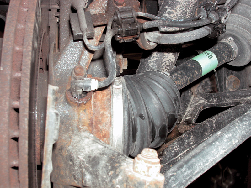
You’ll commonly find small particles of metal clinging pointlike to the inboard surface of the wheelspeed sensors. This occurs because they surround a magnet and operate in an environment that tosses a lot of road grit and debris their way, including some of these ferrous pieces. They are both harmless and unavoidable on the insulation side of the sensor.
Iron particles at the inside of the sensor, the pickup points, or particles stuck between the teeth of the toothed rotor are a different story. At the sensor tip, such a particle can distort the magnetic field so the sensor can’t generate a recognizable signal. Between the teeth, a ferrous particle could make those two teeth look like a single one, just what you’d see during wheel lockup, fooling the control unit into adopting ABS countermeasures or toggling the system off and lighting the ABS lamp.
It used to be easier to inspect the toothed rotors than it is now. The reason it’s harder now is that it was also easier for such particles to find their way between the teeth. Burying the rotor out of easy sight also buries it out of easy metallic contamination.
The signal from the toothed wheel need not be exactly the same as that of every other wheel. After all, under many driving conditions each wheel turns at a different speed. The question is only whether the wheels move at different speeds compatible with the turn the car is in. Later systems employ information from a steering wheel position sensor to calculate the intended radius of the turn and thus the range of allowable wheelspeed difference. But as mentioned earlier, different diameter tires can flag a false sensor fault.
Bleeding techniques are the same for a vehicle with ABS as without, though the importance of flushing the brake fluid with new regularly is more important when there are components as expensive as the hydraulic unit in the circuit. If air gets into the system, it may be necessary to flush the system repeatedly or even operate the vehicle under conditions that will trigger the ABS to clear all the air out of the system.
The overvoltage protection relay can prevent the ABS system from working if it has failed itself. Similarly, if the charging system can’t reach a threshold voltage (about 11 volts), the ABS system won’t turn on. It would be very frustrating to spend very much time doing electrical diagnosis of the ABS system before discovering the alternator wasn’t putting out enough power.


0 Comments