

Wiring repairs, hidden under layers of electrical tape, will remain unseen and unnoticed, unless they fail and require exhumation.
Wiring repairs, hidden under layers of electrical tape, will remain unseen and unnoticed, unless they fail and require exhumation. Some technicians may feel that if a circuit’s function can be restored with a quick repair, there is no reason to spend extra time using Nissan-approved methods. However, professional integrity will prevent most technicians from taking shortcuts, even if their repair work is hidden where no one will ever see it.
This article is for those who want to restore or improve their customer’s wiring, rather than simply fix it. For those who want the satisfaction of knowing that when a car they’ve repaired goes to the car crusher, it may be falling apart at the seams, but their wiring repair will still be in perfect condition. For those who want to be able look their customers straight in the eye and be proud of the repairs they’ve performed.
Address the cause of the failure

CORRECT: Using a T-pin to backprobe an electrical connector. Be sure not to allow the pins to short. Electrical tape can be used to prevent shorting when testing adjacent pins on tightly packed connectors.
Some wiring problems can be caused by an engineering miscalculation or manufacturing error, but it’s extremely rare, and a TSB will usually address the issue. For the most part, wiring harness and connector failures are caused by “something”; finding that “something” and correcting it is the first step in performing a proper repair.
Flex, or excessive harness movement, is one potential cause of failure. It can loosen connector pin fit over time, and it can fatigue copper wire, causing it to break, one strand at a time. Both of these failures will lead to increasing voltage drop and decreasing circuit efficiency little by little until the circuit fails to operate as designed.

INCORRECT: Improper use of a piercing probe can push strands of shielding into the conductor and create a short to ground.
Some flex is unavoidable. The harness to the driver’s door is an example of this. However, other flex can be corrected, such as excessive harness movement caused by worn motor mounts, or flex caused by a misrouted wiring harness.
Discoloration of terminals or wires, or melted insulation, or connector housings is a sure sign of voltage drop and overheating. When there are signs of overheating, the cause should be found. Is it a problem that will be resolved during the course of repair, such as a voltage drop due to poor pin fit, or broken wire strands due to flex? Or could there be a problem that will remain after the repair, such as excessive load on the circuit due to modification or mechanical failure.
Once the wiring is repaired, check for excessive current draw. Examples of common problems include failing or obstructed blower motors, aftermarket or incorrect wattage bulbs, binding window runs or regulators, and devices running at beyond their rated duty cycle.
Testing

Sure, it works, but for how long?
Voltage drop testing is the preferred method for finding a section of harness in need of repair. Resistance testing (using an ohmmeter) will not reveal tenuous connections or frayed wire. For more information on voltage drop, see the E-Learning module: Introduction to Electrical Components (available on http://www.nissan-techinfo.com).
Tug and wiggle testing are invaluable tools when used in conjunction with voltage drop testing. First, tug on the suspect connector to make sure it is fully locked. Then tug on each wire individually to make sure it is fully locked in the connector. Follow tug testing with wiggle testing. Wiggle the connector while monitoring the voltage drop across the connector.
Nissan recommends using T-pins to backprobe non-weatherproofed connectors. If you are a fan of piercing probes, be sure that you do not pierce a shielded wire, leave un-repaired holes in the insulation, or otherwise damage the wiring.
What about blind connectors, such as those found on components like control units and sensors? There is no way to test voltage drop across the connector because there is no access to the other side of the connector. Nissan has a test gauge set available through TechMate to address this problem. Using a connector application guide and color-coded test gauges, worn female terminal springs can be identified. See the Nissan and Infiniti Terminal Pin Service Manual, available from TechMate at www.nissantechmate.com for more information.
Repairing Connectors
Nissan put a lot of thought into using their connector choices. Depending on application, connectors have different levels of weather resistance, different latching mechanisms, and different terminal designs. Repairing the original connector will provide a solid long-lasting repair if done properly, yet it’s common to see jury-rigged solutions applied.
One reason may be that folks are unaware that connector repair parts are available. Connector repair parts are not sold through Nissan parts departments, so if you call for a specific connector for a specific car, you may be told that it is only available with the harness. However, you can purchase all types of connector housings, terminals, weather packing through TechMate.
Complete instructions for repairing each type of terminal, including procedures, terminal part numbers, and required tools can be found in the Nissan and Infiniti Terminal Pin Service Manual, also available on the Techmate website.
Choosing wire

Wire with a higher strand count is better suited to applications where the wire will flex in service. Both wires pictured are 8 GA, but the wire on the right has a higher strand count and thicker insulation, and is therefore a better choice for automotive applications.
Gauge, or the thickness of the conductor, has a direct impact on its current carrying capacity. AWG (American Wire Gauge) is a very old standard particular to North America, and it’s a little counterintuitive. As the thickness of the wire increases, the AWG number decreases. Therefore, a 14 AWG wire is thinner than a 12 AWG.

460F is the ideal temperature for soldering with 60/40 solder.
When selecting replacement wire, the new wire must be as thick or thicker than the wire that is being replaced. So, if a section of 18 gauge wire is being replaced, 16 gauge would be appropriate, but 22 gauge would not. Using thinner wire will result in a voltage drop and poor circuit performance.
Wire gauge is not the only consideration. Wire used in automotive applications, especially when it’s used in sections of harness that will flex, should have a high strand count, meaning the wire should be made up of many fine strands as opposed to fewer thicker strands. There is generally no indication of strand count included in wire specifications, so visual comparison against the original wire is the only way to determine a replacement wire’s suitability.
 Strip equal lengths of insulation from the ends of the wires. Only solder clean bright wire. |
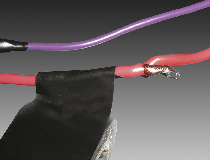
 Twist the ends together. |
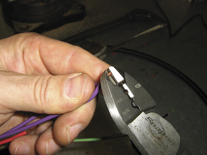 Snip the top to remove any jagged edges. |
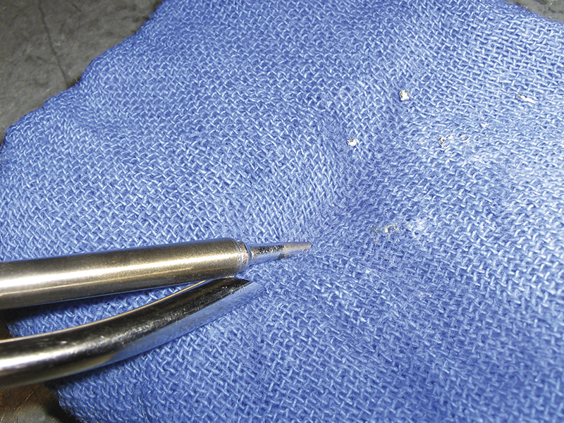 Prepare the soldering iron by tinning |
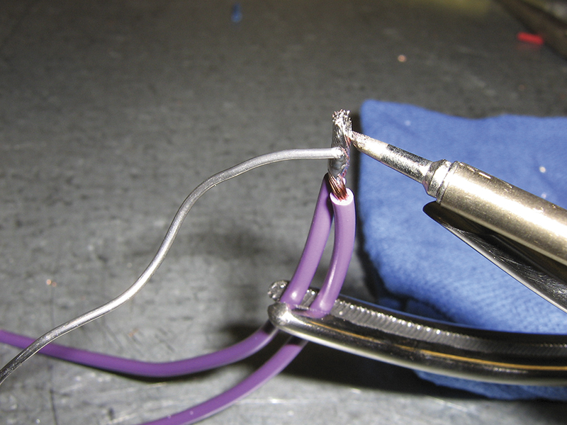 Solder the joint. Don’t allow the joint to |
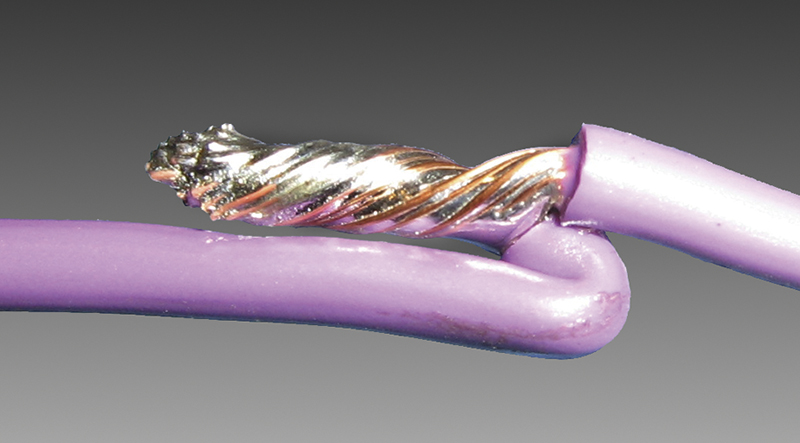 Bend the soldered joint so it lays flat. |
Joining Wire
Nissan’s preferred method of joining wires is solder. A complete discussion of proper soldering technique deserves an article of its own, but here are a few tips, which if combined with practice, should produce good results.
- Always heat the wire, not the solder. Melt the solder into the wire once it’s up to temperature.
- Don’t allow the joint to move as the solder is cooling. Doing so will produce a cold solder, which can be identified by a dull appearance. A good solder joint will appear shiny.
- Clean the soldering iron tip frequently by wiping it on a damp sponge. The oxide crust that forms on the soldering iron tip will decrease heat transfer, and make soldering difficult.
- Use a temperature-controlled soldering iron. You’ll find your soldering “skill” suddenly improves when using a quality tool. Set the temperature to 460 degrees F when using 60/40 solder.
When two wire ends are joined, Nissan recommends twisting the ends together, snipping the tip, soldering, then laying the repair flat against the wire, and taping. Twisting the wires together decreases the likelihood the wires will shift as the solder is cooling, which could produce a cold solder joint. Snipping the tip removes excess wire that could become a sharp protrusion and poke through the electrical tape. Laying the wire flat reduces the bulk of the repair and allows for better sealing.
When choosing where to place repairs, consider how the placement will affect the durability of the harness. If you’re repairing several adjacent wires, stagger the placement of the repairs by 30 mm. This will prevent the repaired sections from rubbing against each other, and keep the harness from looking like a python after a meal.
Never make a repair in a flexible section of harness, near hinges or between the firewall and engine are examples of bad spots for repair. Instead of soldering wire in the flexible section of harness, run new wire through the entire section and solder it in an area that does not flex.
Insulating the repair
Nissan recommends wrapping solder repairs in PVC (Vinyl) electrical tape. Purchasing high quality tape is a good investment. You’ll find quality brands offer better adhesion, stretch, insulation, and protection.
When wrapping a repair with tape, Nissan recommends overlapping the tape by 50%; half the width of each turn of the tape covers the previous turn, and the other half is laid over the repaired section.
Nissan also recommends making 1½ “trips” over the repair. Start wrapping from a point to one side of the repair, wrap over the repair to an equidistant point to the other side of the repair, reverse direction and wrap back to the starting point, reverse direction again, then wrap until over the repair and cut the tape.
When making repairs in the engine compartment or other areas that will be exposed to moisture, Nissan recommends wrapping the repair with butyl (rubber) tape first, then with PVC electrical tape to provide a waterproof seal.
You may find butyl tape elusive. Heat shrink tubing with an adhesive liner is another excellent choice for repairs in potentially moist environments.
 Begin wrapping to one side of the repair. |
 Wrap over the repair to an equidistant point on the other side of the repair, overlapping the tape by 50%. |
 Wrap back to the starting point. |
 Reverse again and wrap back to the center of the repair. |
 Cut the tape rather than pulling apart for neater appearance and better adhesion. |
 A completed repair with staggered joints. |

Use flex conduit to protect wiring.
Protecting the harness
Once a harness has been repaired, it needs to be protected; otherwise the repair may be short lived. Flexible conduit should be installed over the repair to protect the wiring from chafing, protect the wiring from heat, and provide a professional OE appearance.
Loom clips and routing devices should be reinstalled if they are still in good condition, or replaced if they’re damaged or missing. Every part of the original harness is necessary for long term reliability. Obviously, if the original cause of the failure is known (a bad motor mount for instance), it should be repaired

Heat shrink tubing with an adhesive liner protects the solder joint and seals out moisture.
SPECIAL TYPES of WIRING
Air bag wiring
SRS wiring should never be fixed under any circumstance. Customers will sometimes insist on a less expensive solution when told they need an SRS harness. No matter how confident you are you can fix it, and no matter how much they plead, don’t do it. SRS repair is a matter of life and death, and its shielded harnesses with gold plated terminals cannot be properly repaired.
Shielded wiring
Shielded wiring can be repaired at the ends, near the terminals, up to the point where the shielding starts. Sections covered by shielding should not be repaired. Cutting the shielding to make a repair, even if the shielding is replaced once the repair is complete, will diminish the efficacy of the shielding.
Data wiring
CAN bus wiring is twisted to cancel electromagnetic interference (EMI). When repairs are made, the twisted pair must be maintained, or the resistance to EMI will be lost. Running a patch with straight wire is likely to cause network errors and diagnostic headaches.
Conclusion
Do quality electrical repairs take time? Yes, they do, but the more often you use proper procedures, the more practice you’ll get and the faster you’ll become. Once you’re proficient and you have a system in place and tools at the ready, there’s no reason you shouldn’t be fairly compensated for the time you spend fixing your customer’s car the right way.
Your customer may not know what’s hidden under the tape, and he or she may not even remember or appreciate your repairs years later, when the circuit is still working properly. But there’s no reason you shouldn’t take some satisfaction in a job well done.


0 Comments